EP0118412A2 - Method of carrying out melting, melt-metallurgical and/or reduction-metallurgical processes in a plasma melting furnace as well as an arrangement for carrying out the method - Google Patents
Method of carrying out melting, melt-metallurgical and/or reduction-metallurgical processes in a plasma melting furnace as well as an arrangement for carrying out the method Download PDFInfo
- Publication number
- EP0118412A2 EP0118412A2 EP84890010A EP84890010A EP0118412A2 EP 0118412 A2 EP0118412 A2 EP 0118412A2 EP 84890010 A EP84890010 A EP 84890010A EP 84890010 A EP84890010 A EP 84890010A EP 0118412 A2 EP0118412 A2 EP 0118412A2
- Authority
- EP
- European Patent Office
- Prior art keywords
- plasma
- plasma torches
- furnace
- torches
- additional gas
- Prior art date
- Legal status (The legal status is an assumption and is not a legal conclusion. Google has not performed a legal analysis and makes no representation as to the accuracy of the status listed.)
- Withdrawn
Links
Images
Classifications
-
- C—CHEMISTRY; METALLURGY
- C21—METALLURGY OF IRON
- C21B—MANUFACTURE OF IRON OR STEEL
- C21B13/00—Making spongy iron or liquid steel, by direct processes
- C21B13/12—Making spongy iron or liquid steel, by direct processes in electric furnaces
- C21B13/125—By using plasma
-
- C—CHEMISTRY; METALLURGY
- C22—METALLURGY; FERROUS OR NON-FERROUS ALLOYS; TREATMENT OF ALLOYS OR NON-FERROUS METALS
- C22B—PRODUCTION AND REFINING OF METALS; PRETREATMENT OF RAW MATERIALS
- C22B4/00—Electrothermal treatment of ores or metallurgical products for obtaining metals or alloys
- C22B4/005—Electrothermal treatment of ores or metallurgical products for obtaining metals or alloys using plasma jets
-
- C—CHEMISTRY; METALLURGY
- C22—METALLURGY; FERROUS OR NON-FERROUS ALLOYS; TREATMENT OF ALLOYS OR NON-FERROUS METALS
- C22B—PRODUCTION AND REFINING OF METALS; PRETREATMENT OF RAW MATERIALS
- C22B9/00—General processes of refining or remelting of metals; Apparatus for electroslag or arc remelting of metals
- C22B9/16—Remelting metals
- C22B9/22—Remelting metals with heating by wave energy or particle radiation
- C22B9/226—Remelting metals with heating by wave energy or particle radiation by electric discharge, e.g. plasma
-
- F—MECHANICAL ENGINEERING; LIGHTING; HEATING; WEAPONS; BLASTING
- F27—FURNACES; KILNS; OVENS; RETORTS
- F27B—FURNACES, KILNS, OVENS, OR RETORTS IN GENERAL; OPEN SINTERING OR LIKE APPARATUS
- F27B3/00—Hearth-type furnaces, e.g. of reverberatory type; Tank furnaces
- F27B3/08—Hearth-type furnaces, e.g. of reverberatory type; Tank furnaces heated electrically, with or without any other source of heat
-
- H—ELECTRICITY
- H05—ELECTRIC TECHNIQUES NOT OTHERWISE PROVIDED FOR
- H05B—ELECTRIC HEATING; ELECTRIC LIGHT SOURCES NOT OTHERWISE PROVIDED FOR; CIRCUIT ARRANGEMENTS FOR ELECTRIC LIGHT SOURCES, IN GENERAL
- H05B7/00—Heating by electric discharge
-
- F—MECHANICAL ENGINEERING; LIGHTING; HEATING; WEAPONS; BLASTING
- F27—FURNACES; KILNS; OVENS; RETORTS
- F27D—DETAILS OR ACCESSORIES OF FURNACES, KILNS, OVENS, OR RETORTS, IN SO FAR AS THEY ARE OF KINDS OCCURRING IN MORE THAN ONE KIND OF FURNACE
- F27D99/00—Subject matter not provided for in other groups of this subclass
- F27D99/0001—Heating elements or systems
- F27D99/0006—Electric heating elements or system
- F27D2099/0031—Plasma-torch heating
-
- Y—GENERAL TAGGING OF NEW TECHNOLOGICAL DEVELOPMENTS; GENERAL TAGGING OF CROSS-SECTIONAL TECHNOLOGIES SPANNING OVER SEVERAL SECTIONS OF THE IPC; TECHNICAL SUBJECTS COVERED BY FORMER USPC CROSS-REFERENCE ART COLLECTIONS [XRACs] AND DIGESTS
- Y02—TECHNOLOGIES OR APPLICATIONS FOR MITIGATION OR ADAPTATION AGAINST CLIMATE CHANGE
- Y02P—CLIMATE CHANGE MITIGATION TECHNOLOGIES IN THE PRODUCTION OR PROCESSING OF GOODS
- Y02P10/00—Technologies related to metal processing
- Y02P10/10—Reduction of greenhouse gas [GHG] emissions
- Y02P10/134—Reduction of greenhouse gas [GHG] emissions by avoiding CO2, e.g. using hydrogen
Definitions
- the invention relates to a method for performing melting, melt metallurgical and / or reduction metallurgical processes in a P lasmaschmelzofen, in the interior free-burning plasma torches are produced by the lid or by the side walls of the furnace body guided plasma torches and a bottom electrode between, and be melted or umzu-reactants are charged in the area of the plasma torches, and a device for performing the method.
- argon, nitrogen, helium or hydrogen being usually used as the plasma gas.
- the length of the plasma torches that form depends on the size of the voltage gradient, which means that the gas torch is longer for a gas with a lower voltage gradient under otherwise identical conditions.
- S o h at when using argon as P läsmagas and a voltage of about 800 V the plasma torch has a length m up to about 1, whereas when using hydrogen as plasma gas and the same voltage and current, the torch has a length of only about 10 cm .
- the invention aims to avoid these disadvantages and has as its object to create a method and the associated devices in order to increase the energy input into the batches to be melted or converted and thus to improve the thermal efficiency or the kinetics of the process.
- the invention is based on the knowledge that both the length of the torches and the energy output can be regulated, in particular increased, by forming plasma torches which contain different gases with different voltage gradients.
- the invention consists in a method of the type described in the introduction that additional gas streams different from the original plasma gas are introduced into the free-burning plasma torches in order to melt the energy input into the increase liquid reaction bath or regulate its temperature.
- the additional gas streams are fed through porous stones or nozzles in the bottom of the plasma furnace, where they strike the impingement surfaces (focal spots) of glass candles directed obliquely onto the surface of the melted material (sump surface).
- finely divided additives or reaction substances can be suspended in the additional gas streams and fed to the reaction bath.
- finely divided aggregates or R e syndromes- substances lime, ores, ferroalloys, coal or. materials containing iron oxide can be used.
- Another embodiment of the invention can consist in that gas-developing substances are added to the feedstocks to be melted or converted, for example coal, which gasifies to CO, the resulting CO mixing with the plasma gas.
- zones can be formed which, for example, consist of pure argon at the mouth, a mixed gas of argon and CO in the middle of the plasma torch and pure CO at the bath surface.
- the voltage gradient of CO has been found to be about three to four times that of argon under the same conditions, it corresponds like that of helium. With these properties it is possible to shorten a plasma torch, which is about 1 m long at 800 V, to about 25 cm at full power and at the same time to bring the radiated energy maximum closer to the bath.
- coal When coal is used as an additive, not only is the radiated energy of the plasma torch better utilized, but the combustion energy of the coal is also used in the presence or introduction of oxygen.
- the invention further comprises a device for carrying out the method according to the invention with an oven, through the cover or side walls of which plasma torches are guided and in the bottom of which a counterelectrode is arranged.
- This device is characterized in that feed devices are provided for additional gas flows in the area of the plasma torches.
- porous stones or nozzles are provided in the bottom of the furnace for supplying the additional gas streams, preferably at the points which are vertically below the impact surfaces (focal spots) of the plasma torches.
- a horizontally directed inlet for a gas stream is advantageously provided in the area of the sump surface.
- the plasma torches are expediently displaceable in the axial direction in order to regulate the length of the plasma torches.
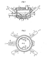
- FIG. 1 is a vertical section and in Fig. 2 is a plan view of the furnace with the cover removed.
- Fig. 1 denotes the fireproof-lined furnace body, on which a fireproof-lined cover 2 is placed, which has a gas exhaust line 3.
- Four plasma torches 4 are guided laterally through the furnace walls and are mounted on a carriage 5 so as to be displaceable in the axial direction and can be pivoted with the carriage.
- the counter electrode 6 is arranged in the bottom of the furnace.
- the torches produced by the plasma torches are denoted by 7 and their impact surfaces on the bath 9 (focal spots) after the starting materials have melted down by 8.
- Porous stones 10 are arranged vertically below, through which additional gas flows are introduced during the melting down of the feed material. In the area of the sump surface there is also a horizontally directed inlet 11 for an additional gas flow. This can also be useful to b-engraving retain 12 possibly existing slag during the casting of the molten material through the A, or to facilitate deslagging by the oven door.
- the batch was repeated using the feed of the same composition, but coal dust suspended in air was blown into the furnace through a steel lance; the length of the torch was reduced to 20 cm and the total voltage rose to 320 V.
- the CO content was over 60% in the furnace chamber.
- the required melting energy was reduced to 600 kWh / t, which means that the energy input into the melting material was considerably improved and the transfer of heat to the furnace walls was reduced accordingly.
- D a-a formed a plasma gas, which consisted of argon at the mouth of the burner, but CO at the point of impact of the swamp formed.
- the degree of metallization of the process is 93%.
- the total energy of about 3000 kWh / t which is usually to be used in such processes has been reduced to about 2500 kWh / t according to the invention.
- the formation of the various zones is accomplished by adding less argon than is normally the case.
Abstract
Bei dem Verfahren werden im Innenraum des Plasmaschmelzofens frei brennende Plasmafackeln zwischen durch den Deckel oder durch die Seitenwände des Ofenkörpers geführten Plasmabrennern und einer Bodenelektrode erzeugt und einzuschmelzende bzw. umzusetzende Zuschlag- bzw. Reaktionsstoffe werden in den Bereich der Plasmafackeln chargiert. Um den thermischen Wirkungsgrad und damit die Kinetik des Prozesses in den aufzuschmelzenden bzw. umzusetzenden Chargen zu verbessern, wird die Erkenntnis, daß durch Ausbildung von Plasmafackeln, die verschiedene Gase mit verschiedenem Spannungsgradienten enthalten, sowohl die Länge der Fackeln als auch die Energieabgabe geregelt, insbesondere erhöht werden kann, genützt, indem zusätzliche, vom ursprünglichen Plasmagas verschiedene Gasströme in die frei brennenden Plasmafackeln eingeleitet werden, um den Energieeintrag in das schmelzflüssige Reaktionsbad zu erhöhen bzw. dessen Temperatur zu regeln. Bei der Einrichtung mit einem Ofen, durch dessen Deckel (2) bzw. Seitenwände Plasmabrenner (4) geführt sind und in dessen Boden eine Gegenelektrode (6) angeordnet ist, sind Zuführvorrichtungen für zusätzliche Gasströme in den Bereich der Plasmafackeln (7) vorgesehen.In the process, freely burning plasma torches are generated in the interior of the plasma melting furnace between plasma torches guided through the cover or through the side walls of the furnace body and a bottom electrode, and additives or reaction substances to be melted or converted are charged in the area of the plasma torches. In order to improve the thermal efficiency and thus the kinetics of the process in the batches to be melted or to be converted, the knowledge that the formation of plasma torches which contain different gases with different voltage gradients regulates both the length of the torches and the energy output, in particular can be used by introducing additional gas streams different from the original plasma gas into the free-burning plasma torches in order to increase the energy input into the molten reaction bath or to regulate its temperature. In the case of the device with a furnace, through the cover (2) or side walls of which plasma torches (4) are guided and in the bottom of which a counterelectrode (6) is arranged, supply devices for additional gas flows into the area of the plasma torches (7) are provided.
Description
Die Erfindung betrifft ein Verfahren zur Durchführung von Schmelz-, schmelzmetallurgischen und/oder reduktionsmetallurgischen Prozessen in einem Plasmaschmelzofen, in dessen Innenraum frei brennende Plasmafackeln zwischen durch den Deckel oder durch die Seitenwände des Ofenkörpers geführten Plasmabrennern und einer Bodenelektrode erzeugt werden, und einzuschmelzende bzw. umzu-Reaktionsstoffe in den Bereich der Plasmafackeln chargiert werden, sowie eine Einrichtung zur Durchführung des Verfahrens.The invention relates to a method for performing melting, melt metallurgical and / or reduction metallurgical processes in a P lasmaschmelzofen, in the interior free-burning plasma torches are produced by the lid or by the side walls of the furnace body guided plasma torches and a bottom electrode between, and be melted or umzu-reactants are charged in the area of the plasma torches, and a device for performing the method.
Verfahren dieser Art sind bekannt, wobei als Plasmagas üblicherweise Argon, Stickstoff, Helium oder Wasserstoff verwendet werden. Diese Gase haben einen verschiedenen elektrischen Spannungsgradienten (E = U·cm-1), wobei Argon dem niedrigsten und Wasserstoff den höchsten Spannungsgradienten aufweisen. Von der Größe des Spannungsgradienten ist die Länge der sich ausbildenden Plasmafackeln abhängig, was bedeutet, daß bei einem Gas mit niedrigerem Spannungsgradienten unter sonst gleichen Bedingungen die Plasmafackel länger ist. So hat bei Verwendung von Argon als Pläsmagas und einer Spannung von etwa 800 V die Plasmafackel eine Länge bis zu etwa 1 m, wogegen bei Verwendung von Wasserstoff als Plasmagas und gleicher Spannung und Stromstärke die Fackel eine Länge von nur etwa 10 cm aufweist.Methods of this type are known, argon, nitrogen, helium or hydrogen being usually used as the plasma gas. These gases have a different electrical voltage gradient (E = U · cm -1 ), with argon having the lowest and hydrogen having the highest voltage gradient. The length of the plasma torches that form depends on the size of the voltage gradient, which means that the gas torch is longer for a gas with a lower voltage gradient under otherwise identical conditions. S o h at when using argon as P läsmagas and a voltage of about 800 V, the plasma torch has a length m up to about 1, whereas when using hydrogen as plasma gas and the same voltage and current, the torch has a length of only about 10 cm .
Bei der Durchführung von Schmelz- und Reduktionsprozessen unter Verwendung von Plasmafackeln als Energieträger wurde die durch Strahlung abgegebene Energie der Plasmafackeln nicht in erwünschter Weise ausgenutzt, weil die höchste Energiedichte der Plasmafackeln nahe der Plasmabrennermündungen entwickelt wird. Der Plasmastrahl wird, je weiter er von der Mündung entfernt ist, aufgefächert und damit energieärmer, indem die abgegebene Energie in Abhängigkeit vom Abstand von der Mündung fortlaufend abnimmt. Dies hat zur Folge, daß insbesondere bei Aufschmelzprozessen, bei welchen durch das Niederschmelzen stückiger Einsatzstoffe ein Sumpf gebildet wird, im Laufe des Schmelzprozesses dem Bad immer weniger Energie zugeführt wird, wogegen ein unerwünscht großer Teil der Energie an die Ofeninnenwände abgegeben wird. Ein Nachfahren der Plasmabrenner hat wenig Wirkung, weil dadurch die Bögen kürzer werden und mit sinkender Spannung die abgegebene Energie zurückgeht.When melting and reduction processes were carried out using plasma torches as energy sources, the energy of the plasma torches emitted by radiation was not used in a desired manner because the highest energy density of the plasma torches is developed near the plasma torch orifices. The farther away it is from the mouth, the plasma jet is fanned out and therefore less energetic, since the energy emitted decreases continuously depending on the distance from the mouth. The result of this is that less and less energy is supplied to the bath in the course of the melting process, in particular in the case of melting processes in which a sump is formed by the melting of lumpy feedstocks, whereas an undesirably large part of the energy is released to the furnace inner walls. Tracing the plasma torch has little effect, because it makes the arches shorter and the energy released decreases as the voltage drops.
Die Erfindung bezweckt die Vermeidung dieser Nachteile und stellt sich die Aufgabe, ein Verfahren sowie die zugehörigen Einrichtungen zu schaffen, um den Energieeintrag in die aufzuschmelzenden bzw. umzusetzenden Chargen zu erhöhen und damit den thermischen Wirkungsgrad bzw. die Kinetik des Prozesses zu verbessern. Die Erfindung beruht auf der Erkenntnis, daß durch Ausbildung von Plasmafackeln, die verschiedene Gase mit verschiedenem Spannungsgradienten enthalten, sowohl die Länge der Fackeln als auch die Energieabgabe geregelt, insbesondere erhöht werden kann.The invention aims to avoid these disadvantages and has as its object to create a method and the associated devices in order to increase the energy input into the batches to be melted or converted and thus to improve the thermal efficiency or the kinetics of the process. The invention is based on the knowledge that both the length of the torches and the energy output can be regulated, in particular increased, by forming plasma torches which contain different gases with different voltage gradients.
Dementsprechend besteht die Erfindung bei einem Verfahren der eingangs beschriebenen Art darin, daß zusätzliche, vom ursprünglichen Plasmagas verschiedene Gasströme in die frei brennenden Plasmafackeln eingeleitet werden, um den Energieeintrag in das schmelzflüssige Reaktionsbad zu erhöhen bzw. dessen Temperatur zu regeln.Accordingly, the invention consists in a method of the type described in the introduction that additional gas streams different from the original plasma gas are introduced into the free-burning plasma torches in order to melt the energy input into the increase liquid reaction bath or regulate its temperature.
Nach einer bevorzugten Ausführungsform werden die zusätzlichen Gasströme durch poröse Steine oder Düsen im Boden des Plasmaofens zugeleitet, wobei sie die Auftreffflächen (Brennflecke) von schräg auf die Oberfläche des Einschmelzgutes (Sumpfoberfläche) gerichteten Pläsmafäckeln treffen.According to a preferred embodiment, the additional gas streams are fed through porous stones or nozzles in the bottom of the plasma furnace, where they strike the impingement surfaces (focal spots) of glass candles directed obliquely onto the surface of the melted material (sump surface).
Es ist aber auch möglich, die zusätzlichen Gasströme auf andere Weise in die Plasmafackeln einzuleiten und damit deren Zusammensetzung zu ändern, beispielsweise mit Hilfe von Rohrbündeln, die konzentrisch um den bzw. die Plasmabrenner angeordnet sind oder aber auch durch seitlich durch die Ofenwand geführte Strahlrohre.However, it is also possible to introduce the additional gas flows into the plasma torches in a different way and thus to change their composition, for example with the aid of tube bundles which are arranged concentrically around the plasma torch or torches, or else through jet tubes which are guided laterally through the furnace wall.
Erfindungsgemäß ist es auch möglich, daß in den zusätzlichen Gasströmen feinteilige Zuschlag- bzw. Reaktionsstoffe suspendiert und dem Reaktionsbad zugeführt werden. Hierbei können als feinteilige Zuschlag- bzw. Reaktions- stoffe Kalk, Erze für Ferrolegierungen, Kohle oder . eisenoxidhältige Materialien verwendet werden.According to the invention, it is also possible for finely divided additives or reaction substances to be suspended in the additional gas streams and fed to the reaction bath. In this case can be used as finely divided aggregates or R eaktions- substances lime, ores, ferroalloys, coal or. materials containing iron oxide can be used.
Eine andere Ausführüngsform der Erfindung kann darin bestehen, daß den einzuschmelzenden bzw. umzusetzenden Einsatzstoffen gasentwickelnde Stoffe zugesetzt werden, z.B. Kohle, die zu CO vergast, wobei das entstehende CO sich mit dem Plasmagas vermischt. Je nach der Einbringungsstelle der zusätzlichen Gasströme können Zonen gebildet werden,' die beispielsweise an der Mündung aus reinem Argon, in der Mitte der Plasmafackel aus einem Mischgas aus Argon und CO und an der Badoberfläche aus reinem CO bestehen. Der Spannungsgradient von CO ist, wie gefunden wurde, etwa drei- bis viermal so groß wie der von Argon unter gleichen Bedingungen, er entspricht etwa jenem von Helium. Mit diesen Eigenschaften ist es möglich, eine Plasmafackel, die bei 800 V etwa 1 m lang ist, bei voller Leistung auf etwa 25 cm zu verkürzen und gleichzeitig das abgestrahlte Energiemaximum dem Bad zu nähern.Another embodiment of the invention can consist in that gas-developing substances are added to the feedstocks to be melted or converted, for example coal, which gasifies to CO, the resulting CO mixing with the plasma gas. Depending on the point at which the additional gas flows are introduced, zones can be formed which, for example, consist of pure argon at the mouth, a mixed gas of argon and CO in the middle of the plasma torch and pure CO at the bath surface. The voltage gradient of CO has been found to be about three to four times that of argon under the same conditions, it corresponds like that of helium. With these properties it is possible to shorten a plasma torch, which is about 1 m long at 800 V, to about 25 cm at full power and at the same time to bring the radiated energy maximum closer to the bath.
Bei Verwendung von Kohle als Zuschlagstoff wird nicht nur die abgestrahlte Energie der Plasmafackel besser ausgenutzt, sondern es wird bei gleichzeitiger Anwesenheit bzw. Einbringen von Sauerstoff auch die Verbrennungsenergie der Kohle ausgenutzt.When coal is used as an additive, not only is the radiated energy of the plasma torch better utilized, but the combustion energy of the coal is also used in the presence or introduction of oxygen.
Die Erfindung umfaßt weiters eine Einrichtung zur Durchführung des erfindungsgemäßen Verfahrens mit einem Ofen, durch dessen Deckel bzw. Seitenwände Plasmabrenner geführt sind und in dessen Boden eine Gegenelektrode angeordnet ist. Diese Einrichtung ist dadurch gekennzeichnet, daß Zuführvorrichtungen für zusätzliche Gasströme in den Bereich der Plasmafackeln vorgesehen sind.The invention further comprises a device for carrying out the method according to the invention with an oven, through the cover or side walls of which plasma torches are guided and in the bottom of which a counterelectrode is arranged. This device is characterized in that feed devices are provided for additional gas flows in the area of the plasma torches.
Gemäß einer bevorzugten Ausführungsform sind im Boden des Ofens poröse Steine oder Düsen zur Zuführung der zusätzlichen Gasströme vorgesehen, vorzugsweise an den Stellen, die vertikal unter den Auftreffflächen (Brennflecken) der Plasmafackeln liegen.According to a preferred embodiment, porous stones or nozzles are provided in the bottom of the furnace for supplying the additional gas streams, preferably at the points which are vertically below the impact surfaces (focal spots) of the plasma torches.
Vorteilhaft ist im Bereich der Sumpfoberfläche ein horizontal gerichteter Einlaß für einen Gasstrom vorgesehen.A horizontally directed inlet for a gas stream is advantageously provided in the area of the sump surface.
Zweckmäßig sind die Plasmabrenner in axialer Richtung zwecks Regelung der Länge der Plasmafackeln verschiebbar.The plasma torches are expediently displaceable in the axial direction in order to regulate the length of the plasma torches.
Eine Schmelzanlage zur Durchführung des erfindungsgemäßen Verfahrens ist in der Zeichnung dargestellt, wobei in Fig. 1 ein Vertikalschnitt und in Fig. 2 eine Draufsicht auf den Ofen bei abgenommenem Deckel dargestellt sind.A melting plant for performing the method according to the invention is shown in the drawing, where in Fig. 1 is a vertical section and in Fig. 2 is a plan view of the furnace with the cover removed.
In Fig. 1 ist mit 1 der feuerfest ausgekleidete Ofenkörper bezeichnet, auf dem ein feuerfest ausgekleideter Deckel 2 aufgesetzt ist, der eine Gasabzugsleitung 3 aufweist. Seitlich durch die Ofenwände sind vier Plasmabrenner 4 geführt, die auf einer Lafette 5 in axialer Richtung verschiebbar montiert und mit der Lafette verschwenkbar sind. Im Boden des Ofens ist-die Gegenelektrode 6 angeordnet.In Fig. 1, 1 denotes the fireproof-lined furnace body, on which a fireproof-lined cover 2 is placed, which has a gas exhaust line 3. Four
Die von den Plasmabrennern erzeugten Fackeln sind mit 7 und ihre Auftreffflächen auf das Bad 9 (Brennflecke), nachdem die Einsatzstoffe niedergeschmolzen sind, mit 8 bezeichnet. Vertikal darunter sind poröse Steine 10 angeordnet, durch welche während des Niederschmelzens des Einsatzgutes zusätzliche Gasströme eingeleitet werden. Im Bereich der Sumpfoberfläche ist noch ein horizontal gerichteter Einlaß 11 für einen zusätzlichen Gasström vorgesehen. Dieser kann auch dazu nützlich sein, um beim Abgießen des geschmolzenen Gutes durch den Ab-stich 12 eventuell vorhandene Schlacke zurückzuhalten, bzw. ein Abschlacken durch die Ofentür zu erleichtern.The torches produced by the plasma torches are denoted by 7 and their impact surfaces on the bath 9 (focal spots) after the starting materials have melted down by 8.
Das erfindungsgemäße Verfahren wird durch die folgenden Beispiele näher erläutert:
- In einen Schmelzofen (Fassungsinhalt 1 m3) mit einem zentral durch den Deckel geführten Plasmabrenner wurden 500 kg Ferromangan fines (76 % Mangan, Rest: Kohle, Eisen) chargiert. Der Plasmabrenner wurde mit Argon betrieben, wobei die zugeführte Gasmenge 1 m3/h betrug. Die zugeführte Energie bei einer Spannung von 280 V betrug 300 kW. Die Fackellänge war 32 cm. Die aufgewendete Gesamtenergie betrug 750 kWh/t.
- 500 kg of ferromanganese fines (76% manganese, remainder: coal, iron) were charged in a melting furnace (capacity 1 m 3 ) with a plasma torch guided centrally through the lid. The P was operated with argon lasmabrenner, wherein the supplied amount of gas was 1 m 3 / h. The energy supplied at a voltage of 280 V was 300 kW. The torch length was 32 cm. The total energy used was 750 kWh / t.
Die Charge wurde unter Verwendung des Einsatzgutes gleicher Zusammensetzung wiederholt, wobei jedoch in Luft suspendierter Kohlestaub durch eine Stahllanze in den Ofen eingeblasen wurde; dabei verkürzte sich die Länge der Fackel auf 20 cm und die Gesamtspannung stieg auf 320 V an. Der CO-Gehalt betrug am Ende des Schmelzvorganges über 60 % im Ofenraum. Die erforderliche Schmelzenergie wurde dabei auf 600 kWh/t reduziert, was bedeutet, daß der Energieeintrag in das Schmelzgut erheblich verbessert und die Übertragung der Wärme auf die Ofenwände entsprechend reduziert wurde.The batch was repeated using the feed of the same composition, but coal dust suspended in air was blown into the furnace through a steel lance; the length of the torch was reduced to 20 cm and the total voltage rose to 320 V. At the end of the melting process, the CO content was over 60% in the furnace chamber. The required melting energy was reduced to 600 kWh / t, which means that the energy input into the melting material was considerably improved and the transfer of heat to the furnace walls was reduced accordingly.
Unter Verwendung einer Einrichtung nach den Fig. 1 und 2 wurde Stahlschrott mit einer Dichte von 1,7 t/m niedergeschmolzen, u.zw. wurden 30 t dieses Schrottes in den Ofen chargiert. Die vier Plasmabrenner wurden zu Beginn des Schmelzens mit Argon betrieben, wobei 14 MW bei einer Bogenspannung von 600 V aufgewendet wurden. Zu Beginn und während der ersten Phase des Schmelzens betrug die Länge der Fackeln 1 m, wobei die Spitze der Fackeln in den Schrott hineinreichte. Nach Bildung eines Sumpfes und entsprechendem Kleinerwerden der Oberfläche wurde durch die porösen Bodensteine CO zugeführt und die Plasmafackeln in axialer Richtung gegen den Sumpf verschoben, wobei sich die Fackellänge auf 30 cm bei gleichbleibender Leistung verkürzte. Dabei wurde ein Energieeintrag von 420 kWh/t erreicht, wogegen ohne Zuführung des CO die aufgewendete Gesamtenergie (Einschmelzenergieverbrauch) 470 kWh/t betragen hätte.Using a device according to FIGS. 1 and 2, steel scrap with a density of 1.7 t / m was melted down, etc. 30 tons of this scrap were charged into the furnace. The four plasma torches were operated with argon at the start of melting, using 14 MW at an arc voltage of 600 V. At the beginning and during the first phase of melting, the length of the torches was 1 m, with the tip of the torches reaching into the scrap. After the formation of a sump and the surface becoming correspondingly smaller, CO was introduced through the porous soil stones and the plasma torches were displaced in the axial direction against the sump, the torch length being reduced to 30 cm while the power remained the same. An energy input of 420 kWh / t was achieved, whereas without the addition of the CO the total energy (melting energy consumption) would have been 470 kWh / t.
In einen Reduktionsofen mit 250 1 Inhalt und einem zentralen, durch den Ofendeckel geführten Plasmabrenner, der mit Argon betrieben wurde und eine Spannung von 250 V und 200 kW Leistung hatte, wurden 200 kg LD-Staub folgender. Zusammensetzung: Fegesamt = -40,8 %, Fe metallisch = 0,8 %; FeO = 3,90 %; Fe2O3= 52,.9 %; Zn = 1,35 % chargiert, wobei der Staub durch eine Förderschnecke kontinuierlich zugeführt und in den Strahlungsbereich der Plasmafackel fallend eingebracht wurde. Die zugeführte Menge betrug 30 kg/h. Gleichzeitig wurde Kohlegrus, ebenfalls kontinuierlich in den Bereich der Plasmafackel fallend in einer Menge von 15 kg/h zugeführt. Da-bei bildete sich ein Plasmagas, welches an der Mündung des Brenners aus Argon, an der Auftreffstelle des gebildeten Sumpfes jedoch aus CO bestand. Nach einer Reaktionszeit von 6,5 h entstand ein geschmolzenes Reaktionsprodukt folgender Zusammensetzung: Fe gesamt 88,5 %; Femetallisch = 82.2 %; Fe0 = 1,0 %; Fe2O3 = 7,85 %; Zn = 0,04 %. Der Metallisierungsgrad des Prozesses beträgt damit 93 %.In a reduction furnace with a capacity of 250 l and a central plasma torch, which was led through the furnace cover and was operated with argon and had a voltage of 250 V and a power of 200 kW, 200 kg of LD dust followed. Composition: Fe total = -40.8%, Fe m metallic = 0.8%; FeO = 3.90%; Fe 2 O 3 = 52.9%; Zn = 1.35% charged, whereby the dust was continuously fed through a screw conveyor and introduced into the radiation area of the plasma torch. The amount fed was 30 kg / h. At the same time, coal powder, also falling continuously in the area of the plasma torch, was fed in at a rate of 15 kg / h. D a-a formed a plasma gas, which consisted of argon at the mouth of the burner, but CO at the point of impact of the swamp formed. After a reaction time of 6.5 h, a molten reaction product of the following composition was formed: total Fe 88.5%; Fe metallic = 82.2%; Fe0 = 1.0%; Fe 2 O 3 = 7.85%; Zn = 0.04%. The degree of metallization of the process is 93%.
Die üblicherweise bei solchen Prozessen aufzuwendende Gesamtenergie von etwa 3000 kWh/t wurde erfindungsgemäß auf etwa 2500 kWh/t reduziert.The total energy of about 3000 kWh / t which is usually to be used in such processes has been reduced to about 2500 kWh / t according to the invention.
Bei diesem Beispiel wird die Bildung der verschiedenen Zonen dadurch erreicht, daß weniger Argon als sonst üblich zugeführt wird.In this example, the formation of the various zones is accomplished by adding less argon than is normally the case.
Bei diesem Beispiel wird außerdem eine Entzinkung des LD-Staubes erreicht.In this example, dezincification of the LD dust is also achieved.
Claims (8)
Applications Claiming Priority (2)
| Application Number | Priority Date | Filing Date | Title |
|---|---|---|---|
| AT366/83 | 1983-02-03 | ||
| AT0036683A AT375404B (en) | 1983-02-03 | 1983-02-03 | METHOD FOR CARRYING OUT MELTING, MELTING METALURGICAL AND / OR REDUCTION METALURGICAL PROCESSES IN A PLASMA MELTING FURNACE AND DEVICE FOR CARRYING OUT THE METHOD |
Publications (2)
| Publication Number | Publication Date |
|---|---|
| EP0118412A2 true EP0118412A2 (en) | 1984-09-12 |
| EP0118412A3 EP0118412A3 (en) | 1985-04-17 |
Family
ID=3488689
Family Applications (1)
| Application Number | Title | Priority Date | Filing Date |
|---|---|---|---|
| EP84890010A Withdrawn EP0118412A3 (en) | 1983-02-03 | 1984-01-16 | Method of carrying out melting, melt-metallurgical and/or reduction-metallurgical processes in a plasma melting furnace as well as an arrangement for carrying out the method |
Country Status (11)
| Country | Link |
|---|---|
| US (1) | US4504307A (en) |
| EP (1) | EP0118412A3 (en) |
| JP (1) | JPS59157480A (en) |
| AT (1) | AT375404B (en) |
| AU (1) | AU2409384A (en) |
| CA (1) | CA1214192A (en) |
| DD (1) | DD216482A5 (en) |
| ES (1) | ES529424A0 (en) |
| NO (1) | NO840406L (en) |
| PT (1) | PT78033B (en) |
| ZA (1) | ZA84777B (en) |
Cited By (5)
| Publication number | Priority date | Publication date | Assignee | Title |
|---|---|---|---|---|
| AT385520B (en) * | 1986-07-22 | 1988-04-11 | Voest Alpine Ag | METHOD FOR PRODUCING COPPER AND OVEN FOR CARRYING OUT THE METHOD |
| EP0369642A2 (en) * | 1988-11-17 | 1990-05-23 | TETRONICS RESEARCH & DEVELOPMENT COMPANY LIMITED | Method of melting materials |
| EP0417296A1 (en) * | 1989-01-26 | 1991-03-20 | Manyo Kogyo Kabushiki Kaisha | Direct smelting process |
| EP0625869A2 (en) * | 1993-05-19 | 1994-11-23 | Schuller International, Inc. | Method for the melting, combustion or incineration of materials and apparatus therefor |
| CN103937993A (en) * | 2014-04-01 | 2014-07-23 | 梧州漓佳铜棒有限公司 | Tilting type anode furnace nitrogen gas stirring device |
Families Citing this family (14)
| Publication number | Priority date | Publication date | Assignee | Title |
|---|---|---|---|---|
| US4654076A (en) * | 1986-01-30 | 1987-03-31 | Plasma Energy Corporation | Apparatus and method for treating metallic fines |
| US4699654A (en) * | 1986-04-08 | 1987-10-13 | Union Carbide Corporation | Melting furnace and method for melting metal |
| CA1311787C (en) * | 1986-06-24 | 1992-12-22 | Masahisa Tate | Method of bottom blowing operation of a steel making electric furnace |
| US4806325A (en) * | 1988-07-14 | 1989-02-21 | Fmc Corporation | Process for recovering elemental phosphorus and a metal concentrate from ferrophos |
| US4875985A (en) * | 1988-10-14 | 1989-10-24 | Brunswick Corporation | Method and appparatus for producing titanium |
| US5471495A (en) * | 1991-11-18 | 1995-11-28 | Voest-Alpine Industrieanlagenbeau Gmbh | Electric arc furnace arrangement for producing steel |
| AT396483B (en) * | 1991-11-18 | 1993-09-27 | Voest Alpine Ind Anlagen | DC electric arc steel-making furnace - has peripheral electrodes and bottom anode to obtain high energy input without high capital and operating costs |
| CN1051579C (en) * | 1996-09-18 | 2000-04-19 | 中国科学院力学研究所 | Method and apparatus for smelting high melting metal by plasma |
| CN1098935C (en) * | 1999-11-24 | 2003-01-15 | 武汉科技大学 | AC plasma melting reduction process and equipment for direct smelting of ferroalloy with very low carbon content |
| UA74633C2 (en) * | 2003-10-10 | 2006-01-16 | Anatolii Tymofiiovych Neklesa | A reactor for producing iron or alloys thereof |
| UA75925C2 (en) * | 2003-12-22 | 2006-06-15 | Anatolii Tymofiiovych Neklesa | An assembly for producing metal from the iron-containing raw stock |
| CZ304722B6 (en) * | 2012-08-27 | 2014-09-10 | Vysoká Škola Báňská-Technická Univerzita Ostrava | Two-burner multipurpose plasma furnace |
| RU2562717C1 (en) * | 2014-02-20 | 2015-09-10 | Ашот Александрович Навасардян | Method of producing silicon from silicon oxide |
| RU2746655C1 (en) * | 2020-11-06 | 2021-04-19 | федеральное государственное бюджетное образовательное учреждение высшего образования «Санкт-Петербургский горный университет» | Plasma furnace for corundum production |
Citations (7)
| Publication number | Priority date | Publication date | Assignee | Title |
|---|---|---|---|---|
| DD73363A (en) * | ||||
| US3304169A (en) * | 1960-08-01 | 1967-02-14 | Union Carbide Corp | Method of deoxidizing metals |
| DE1565891A1 (en) * | 1965-04-07 | 1970-04-02 | Union Carbide Corp | Arc furnace |
| DD105370A1 (en) * | 1973-07-30 | 1974-04-12 | ||
| DD111138A1 (en) * | 1974-05-08 | 1975-01-20 | ||
| EP0030932A1 (en) * | 1979-12-14 | 1981-06-24 | VEB Edelstahlwerk 8. Mai 1945 Freital | Process for plasma-melting of metals and alloys |
| EP0056225A1 (en) * | 1981-01-08 | 1982-07-21 | VOEST-ALPINE Aktiengesellschaft | Plasma melting furnace |
Family Cites Families (1)
| Publication number | Priority date | Publication date | Assignee | Title |
|---|---|---|---|---|
| NL130826C (en) * | 1960-08-01 | 1900-01-01 |
-
1983
- 1983-02-03 AT AT0036683A patent/AT375404B/en not_active IP Right Cessation
-
1984
- 1984-01-16 EP EP84890010A patent/EP0118412A3/en not_active Withdrawn
- 1984-01-26 CA CA000446066A patent/CA1214192A/en not_active Expired
- 1984-01-30 PT PT78033A patent/PT78033B/en unknown
- 1984-02-01 US US06/576,030 patent/US4504307A/en not_active Expired - Fee Related
- 1984-02-01 DD DD84259801A patent/DD216482A5/en not_active IP Right Cessation
- 1984-02-02 ES ES529424A patent/ES529424A0/en active Granted
- 1984-02-02 AU AU24093/84A patent/AU2409384A/en not_active Abandoned
- 1984-02-02 NO NO840406A patent/NO840406L/en unknown
- 1984-02-02 ZA ZA84777A patent/ZA84777B/en unknown
- 1984-02-02 JP JP59018175A patent/JPS59157480A/en active Granted
Patent Citations (7)
| Publication number | Priority date | Publication date | Assignee | Title |
|---|---|---|---|---|
| DD73363A (en) * | ||||
| US3304169A (en) * | 1960-08-01 | 1967-02-14 | Union Carbide Corp | Method of deoxidizing metals |
| DE1565891A1 (en) * | 1965-04-07 | 1970-04-02 | Union Carbide Corp | Arc furnace |
| DD105370A1 (en) * | 1973-07-30 | 1974-04-12 | ||
| DD111138A1 (en) * | 1974-05-08 | 1975-01-20 | ||
| EP0030932A1 (en) * | 1979-12-14 | 1981-06-24 | VEB Edelstahlwerk 8. Mai 1945 Freital | Process for plasma-melting of metals and alloys |
| EP0056225A1 (en) * | 1981-01-08 | 1982-07-21 | VOEST-ALPINE Aktiengesellschaft | Plasma melting furnace |
Cited By (8)
| Publication number | Priority date | Publication date | Assignee | Title |
|---|---|---|---|---|
| AT385520B (en) * | 1986-07-22 | 1988-04-11 | Voest Alpine Ag | METHOD FOR PRODUCING COPPER AND OVEN FOR CARRYING OUT THE METHOD |
| EP0369642A2 (en) * | 1988-11-17 | 1990-05-23 | TETRONICS RESEARCH & DEVELOPMENT COMPANY LIMITED | Method of melting materials |
| EP0369642A3 (en) * | 1988-11-17 | 1991-01-09 | TETRONICS RESEARCH & DEVELOPMENT COMPANY LIMITED | Method of melting materials |
| EP0417296A1 (en) * | 1989-01-26 | 1991-03-20 | Manyo Kogyo Kabushiki Kaisha | Direct smelting process |
| EP0417296A4 (en) * | 1989-01-26 | 1991-07-10 | Manyo Kogyo Kabushiki Kaisha | Direct smelting process |
| EP0625869A2 (en) * | 1993-05-19 | 1994-11-23 | Schuller International, Inc. | Method for the melting, combustion or incineration of materials and apparatus therefor |
| EP0625869A3 (en) * | 1993-05-19 | 1995-04-19 | Schuller Int Inc | Method for the melting, combustion or incineration of materials and apparatus therefor. |
| CN103937993A (en) * | 2014-04-01 | 2014-07-23 | 梧州漓佳铜棒有限公司 | Tilting type anode furnace nitrogen gas stirring device |
Also Published As
| Publication number | Publication date |
|---|---|
| AT375404B (en) | 1984-08-10 |
| ATA36683A (en) | 1983-12-15 |
| EP0118412A3 (en) | 1985-04-17 |
| JPS6232246B2 (en) | 1987-07-14 |
| ZA84777B (en) | 1984-10-31 |
| ES8502780A1 (en) | 1985-01-16 |
| NO840406L (en) | 1984-08-06 |
| PT78033A (en) | 1984-02-01 |
| DD216482A5 (en) | 1984-12-12 |
| CA1214192A (en) | 1986-11-18 |
| AU2409384A (en) | 1984-08-09 |
| US4504307A (en) | 1985-03-12 |
| JPS59157480A (en) | 1984-09-06 |
| PT78033B (en) | 1986-03-21 |
| ES529424A0 (en) | 1985-01-16 |
Similar Documents
| Publication | Publication Date | Title |
|---|---|---|
| EP0118412A2 (en) | Method of carrying out melting, melt-metallurgical and/or reduction-metallurgical processes in a plasma melting furnace as well as an arrangement for carrying out the method | |
| DE3629055C2 (en) | ||
| EP0302111B1 (en) | Method and furnace for making iron-carbon intermediate products for steel production | |
| DE69927837T2 (en) | METHOD AND DEVICE FOR PRODUCING METALS AND METAL ALLOYS | |
| DE2723857A1 (en) | METHOD AND DEVICE FOR STEEL PRODUCTION | |
| DE3001722A1 (en) | METHOD FOR CLEANING ALUMINUM | |
| DE2821453B2 (en) | Plasma melting furnace | |
| EP0820528B1 (en) | Iron smelting process and plant according to the multiple zone smelting process | |
| DE2727618C2 (en) | ||
| DE3247572A1 (en) | DEVICE FOR PRODUCING STEEL | |
| AT395478B (en) | MELTING FURNACE AND METHOD FOR FEEDING MATERIAL TO BE PROCESSED IN IT | |
| DE3306910C2 (en) | Manufacture of ferrosilicon | |
| EP0087405A1 (en) | Process and device for the reduction of particle-sized ores containing oxide | |
| DE2900676C2 (en) | ||
| DE2838983B2 (en) | Process for producing steel in the converter | |
| EP0118655B1 (en) | Method of carrying out metallurgical or chemical processes, and a low-shaft furnace | |
| AT408663B (en) | METHOD FOR MELTING IRON SPONGE AND ELECTRIC ARC FURNACE FOR IMPLEMENTING THE METHOD | |
| EP0171385A1 (en) | A process for the production of calcium carbide and a shaft furnace for carrying out the process | |
| DE10333764B3 (en) | Charging fine, directly-reduced iron particles into arc furnace, passes stream of bulk material from downcomer through orifice plate, to enter furnace largely undisturbed | |
| DD219753A5 (en) | APPARATUS FOR GENERATING CALCIUM CARBIDE | |
| DE3590837C2 (en) | ||
| DE3920522A1 (en) | Plant for extracting metallic lead from sulphidic concentrate - has divided chamber with ratio of electrothermic section area to that of vessel, to increase extraction and reduce energy use | |
| CH655383A5 (en) | METHOD FOR ELECTRICALLY MELTING NON-METAL MATERIAL. | |
| EP2659008B1 (en) | Method for the pyrometallurigical treatment of metals, molten metals, and/or slags | |
| EP1090148A1 (en) | Electric arc furnace |
Legal Events
| Date | Code | Title | Description |
|---|---|---|---|
| PUAI | Public reference made under article 153(3) epc to a published international application that has entered the european phase |
Free format text: ORIGINAL CODE: 0009012 |
|
| AK | Designated contracting states |
Designated state(s): BE DE FR GB IT LU NL SE |
|
| PUAL | Search report despatched |
Free format text: ORIGINAL CODE: 0009013 |
|
| AK | Designated contracting states |
Designated state(s): BE DE FR GB IT LU NL SE |
|
| STAA | Information on the status of an ep patent application or granted ep patent |
Free format text: STATUS: THE APPLICATION IS DEEMED TO BE WITHDRAWN |
|
| 18D | Application deemed to be withdrawn |
Effective date: 19851218 |
|
| RIN1 | Information on inventor provided before grant (corrected) |
Inventor name: RIEGLER, ERNST Inventor name: LUGSCHEIDER, WALTER, DR. DIPL.-ING. Inventor name: STEIPE, OTHMAR, DIPL.-ING. Inventor name: ZAJICEK, ERNST |