EP0724363B1 - Vorrichtung zur Dekodierung eines digitalen Signals - Google Patents
Vorrichtung zur Dekodierung eines digitalen Signals Download PDFInfo
- Publication number
- EP0724363B1 EP0724363B1 EP19960300495 EP96300495A EP0724363B1 EP 0724363 B1 EP0724363 B1 EP 0724363B1 EP 19960300495 EP19960300495 EP 19960300495 EP 96300495 A EP96300495 A EP 96300495A EP 0724363 B1 EP0724363 B1 EP 0724363B1
- Authority
- EP
- European Patent Office
- Prior art keywords
- picture
- circuit
- digital signal
- macroblock
- signal
- Prior art date
- Legal status (The legal status is an assumption and is not a legal conclusion. Google has not performed a legal analysis and makes no representation as to the accuracy of the status listed.)
- Expired - Lifetime
Links
Images


Classifications
-
- G—PHYSICS
- G11—INFORMATION STORAGE
- G11B—INFORMATION STORAGE BASED ON RELATIVE MOVEMENT BETWEEN RECORD CARRIER AND TRANSDUCER
- G11B20/00—Signal processing not specific to the method of recording or reproducing; Circuits therefor
- G11B20/10—Digital recording or reproducing
- G11B20/18—Error detection or correction; Testing, e.g. of drop-outs
-
- H—ELECTRICITY
- H04—ELECTRIC COMMUNICATION TECHNIQUE
- H04N—PICTORIAL COMMUNICATION, e.g. TELEVISION
- H04N19/00—Methods or arrangements for coding, decoding, compressing or decompressing digital video signals
- H04N19/85—Methods or arrangements for coding, decoding, compressing or decompressing digital video signals using pre-processing or post-processing specially adapted for video compression
- H04N19/89—Methods or arrangements for coding, decoding, compressing or decompressing digital video signals using pre-processing or post-processing specially adapted for video compression involving methods or arrangements for detection of transmission errors at the decoder
- H04N19/895—Methods or arrangements for coding, decoding, compressing or decompressing digital video signals using pre-processing or post-processing specially adapted for video compression involving methods or arrangements for detection of transmission errors at the decoder in combination with error concealment
Definitions
- This invention relates to digital signal decoding apparatus, and particularly (but not exclusively) to digital signal decoding apparatus to be used for a recording/reproducing apparatus for recording or reproducing a moving picture signal on or from a recording medium such as a magneto-optical disc or magnetic tape, and for a receiver of a television conference system for transmitting or receiving a moving picture signal through a transmission path.
- a proposed system for transmitting a moving picture signal to a remote place such as a television conference system, visual telephone system, or broadcast system has used a method of compressing and encoding a video signal by using line correlation or inter-frame correlation between video signals in order to efficiently use a transmission line.
- line correlation it is possible to compress a video signal by an orthogonal transformation (e.g., DCT (Discrete Cosine Transformation)) encoding processing.
- inter-frame correlation it is possible to further compress the video signal.
- Figs. 1A and 1B show the above encoding method.
- a series of frame groups are processed every 17 frames (frames F1 to F17).
- This processing unit is referred to as a group of pictures.
- the group of pictures are encoded to I-picture, B-picture, and P-picture in order starting with the first frame F1 and the fourth and subsequent frames F4 to F17 are alternately encoded to B-picture or P-picture.
- I-picture is the picture obtained by directly encoding the video signals for one frame.
- P-picture is basically the picture obtained by encoding the difference between the video signals to I-picture temporally preceding the P-picture or the difference between the video signals to temporally preceding P-picture.
- B-picture is basically the picture obtained by encoding the difference between the video signals to the average value between a temporally preceding frame and a temporally following frame. This encoding method is referred to as the bidirectional prediction encoding.
- B-picture uses the following three types of encoding methods in addition to the bidirectional prediction encoding.
- the first processing method directly transmits the data for the original frame F2 as transmission data. This is referred to as inter-encoding which is the same processing as the case of I-picture.
- the second processing method calculates and transmits a difference from the temporally-following frame F3. This is referred to as backward prediction encoding.
- the third processing method transmits a difference from the temporally preceding frame F1. This is referred to as forward prediction encoding.
- the data encoded by the method for minimizing transmission data among these four encoding methods is used as B-picture.
- An actual encoding apparatus further converts the video signals of the frame format (I-picture, P-picture, or B-picture) to block format signals and transmits them in the form of bit streams.
- the frame format I-picture, P-picture, or B-picture
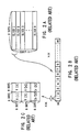
- Figs. 2A to 2C show the block format. As shown in Fig. 2A, V lines of the line composed of H dots for one line are assembled into a frame format video signal.
- the video signal of one frame is divided into N slices each of which comprises 16 lines. Each slice is composed of M macroblocks. Each macroblock is composed of a luminance signal corresponding to 16 x 16 picture elements (dots) and the luminance signal is divided into blocks Y[1] to Y[4] each of which comprises 8 x 8 dots.
- the luminance signal of 16 x 16 dots corresponds to color signals Cb and Cr of 8 x 8 dots.
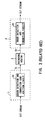
- the decoding apparatus thus receives and decodes the video signal converted to a bit stream through a recording medium or a transmission line. If an error is included in the bit stream read out from a recording medium or the like, this error part may be reflected on a reproduced picture or the like. Therefore, as shown in Fig. 3, an error detection and correction code addition circuit 1A and an error detection and correction circuit 2A are conventionally provided to an encoding apparatus 1 and a decoding apparatus 2 respectively so that a slight error can be corrected.
- an error correction code with a proper length is normally used. Therefore, when a large data error occurs in a bit stream S2, the error cannot be corrected by the error detection and correction circuit 2A in some cases. In this case, there is a problem that it cannot be avoided that an error included in the bit stream S2 is reflected on the reproduced picture.
- the transfer unit access unit of the disc, etc.
- the transfer unit may terminate in the middle of a macroblock.
- the method is used in which an error start code D ES including a synchronous code is inserted into the bit stream S2 so that a decoding circuit can identify the end point in the macroblock.
- the following problem may occur in the macroblock including the error start code D ES .
- an inverse quantizer constituting a decoding circuit and an IDCT (inverse discrete cosine transformation) circuit operate in block units and a movement compensation circuit operates in macroblocks.
- the description is hereafter made by assuming that the bit stream S2 including an uncompleted macroblock is input to a variable-length decoding circuit located at the input stage of the decoding circuit.
- the variable-length decoding circuit supplies a frame/field DCT flag, quantization scale, a prediction mode, movement vector, and frame/field prediction flag to the circuits in rear stage after completing the processing of the header of the macroblock "1" as shown in Fig. 4C. Then, as shown in Fig. 4D, the variable-length decoding circuit supplies picture data to the inverse quantization circuit whenever the processing of each block ends.
- variable-length decoding circuit detects the delimitation of the bit stream by the error start code D ES including a synchronous code.
- the macroblock "2" is uncompleted, it is impossible to complete the processing of the block "2-2". Moreover, it is impossible to complete the processing of the macroblock "2".
- the inverse quantization circuit and IDCT circuit operate in blocks, their operations are damaged unless the processing of the block "2-2" is completed. Moreover, because the movement compensation circuit operates in each macroblock, the operation of the circuit may be damaged unless the processing of the macroblock "2" is completed.
- the method is considered in which a memory circuit for storing the processing results of the variable-length decoding circuit for one macroblock are provided, and then the data is supplied to a circuit in rear stage when the processing for one macroblock completely ends.
- EP-A-0 624 977 which identifies the presence of an uncorrectable error in video data reproduced from a recording medium and replaces the error data by data at a corresponding position in the past.
- An uncorrectable error part or data part including the error part in the digital signal may be replaced with the special code including a synchronous code and output to the decoding means.
- the special code thus replaced may include a synchronous code, and can always be detected by the decoding means. Therefore, it is possible to realize confirmation of presence of an error and error correction at the time of decoding.
- the decoding means outputs the predicted digital signal instead of the decoded signal of the uncompleted data group. Therefore, it is possible to obtain an output signal not influenced by the data in uncompleted data group without adding a special circuit for processing the uncompleted data group.
- Fig. 5 shows the circuit constitution of a decoding apparatus 12.
- the decoding apparatus 12 have a decoding circuit section 13 for preventing an error from reflecting on an output picture by replacing an error part which cannot be corrected sufficiently by an error detection and correction circuit with the error start code D ES including a synchronous code.
- the decoding circuit section 13 is constructed with an error detection and correction circuit 14, an uncorrectable flag conversion circuit 15, and a decoding circuit 16. Each of these circuits is constituted as described below.
- the error detection and correction circuit 14 detects presence or absence of an error included in a recording medium 3 or a bit stream S2 input through a transmission path, and corrects the error by using an error correction code when an error is detected.
- the error detection and correction circuit 14 used in this embodiment outputs an uncorrectable flag D EF together with a bit stream D BS and informs a rear-stage circuit of an uncorrectable error part.
- the uncorrectable flag conversion circuit 15 inputs the bit stream D BS and the uncorrectable flag D EF , and replaces an error part which cannot be corrected sufficiently by the error detection and correction circuit 14 with the error start code D ES .
- an error start code generation circuit 15A receives the uncorrectable flag D EF to detect an error part which cannot be corrected sufficiently by the detection and correction circuit 14, generates the error start code D ES when detecting the error part, and outputs the code D ES to a switching circuit 15B.
- the switching circuit 15B replaces an error part included in the bit stream S2 or a data part including the error part and having the same data length as the error start code D ES with the error start code D ES .
- the error start code D ES is composed of a 32-bit code shown by "00000000 00000000 00000001 10110100".
- Above code is defined by the video signal encoding method generally used at present, in which the initial 24 bits out of 32 bits serve as a synchronous code. Moreover, the final 8 bits serve as an attribute code indicating what the synchronous code represents. In this case, the bits "10110100" serve as an attribute code indicating an error.
- this code must not appear for any combination of codes in a variable-length encoded bit stream, and can be found under any state of decoding in the decoding circuit 16.
- the uncorrectable flag conversion circuit 15 replaces the error part in the bit stream and the part including the error part and corresponding to the length of the error start code D ES with the error start code D ES .
- the error start code D ES is simply inserted into the error part, the data quantity of the bit stream after the insertion of error start code D ES increases compared to that of the bit stream generated by an encoding apparatus by a value equivalent to the error start code D ES .
- the decoding apparatus is a system for controlling generation of bit streams while checking the capacity of a receiving buffer, the possibility that the receiving buffer is broken down cannot be avoided when the data quantity increases as described above.
- a buffer for storing the flag is needed in order to add the flag to a bit stream so as to sufficiently cover the error part. Therefore, the problem arises that the capacity of the buffer increases.
- bit streams equal to the number of bit streams generated by the encoding apparatus are stored in the receiving buffer and it is possible to prevent the receiving buffer from being broken down.
- this embodiment replaces the uncorrectable flag D EF with the error start code D ES just before the receiving buffer (17 in Fig. 6) in order to prevent the capacity of the receiving buffer from increasing by storing the bit stream D BS and moreover the uncorrectable flag.
- the decoding circuit 16 is described below.
- the decoding circuit 16 inputs the bit stream S3 output from the uncorrectable flag conversion circuit 15 through a receiving buffer to execute various decoding processings: variable-length decoding processing; inverse quantization processing; inverse discrete cosine transformation processing; and movement compensation processing, etc..
- the decoding circuit 16 When discriminating the error start code D ES from the bit stream S3, the decoding circuit 16 operates so that a picture including errors is not output from an output terminal in accordance with a series of decoding processings.
- the decoding apparatus 12 corrects code errors existing in the bit stream S2 by the error detection and correction circuit 14 provided at the first stage.
- the error correction circuit 14 replaces predetermined-length data including the error part with the error start code D ES to supply the code to the decoding circuit 16.
- the decoding circuit section 13 decodes the bit stream S3 in order in accordance with a predetermined decoding procedure.
- the decoding circuit section 13 confirms the position of the code part and selects various processing so that no error reflects on a decoded picture.
- the data part including the uncorrectable data error is replaced with the error start code D ES so that the code can be discriminated by the decoding circuit section 13, so that it is possible to select the processing for preventing data errors which cannot be corrected sufficiently by the error detection and correction circuit 14 from reflecting on the decoded picture.
- the decoding circuit 16 makes it possible to continue decoding without damaging the processing by substituting a predicted picture for the part of an uncompleted macroblock even if the macroblock appears at the time of special reproduction (e.g. at the time of fast-forward reproduction or quick-reverse reproduction). Moreover, in this case, because the predicted picture is substituted for the uncompleted macroblock, the uncompleted macroblock is prevented from reflecting on other pictures.
- Fig. 6 shows an example of the decoding circuit 16.
- the decoding circuit 16 captures the bit stream S3 of picture data input through the error detection and correction circuit 14 and the uncorrectable flag conversion circuit 15 in the receiving buffer 17 to temporarily store the bit stream S3.
- a variable-length decoding circuit 18 is a main circuit of this embodiment, which obtains quantization step S4, movement vector S5, prediction mode (information regarding the prediction in the macroblock type) S6, frame/field prediction flag S7 (hereafter referred to as prediction flag S7), and frame/field DCT flag S8 (hereafter referred to as DCT flag S8) by variable-length decoding the data group read out from the receiving buffer 17.
- the variable-length decoding circuit 18 controls a rear-stage processing circuit by supplying the quantization step S4 among these various types of decoding information to the inverse quantization circuit 19, and supplying the movement vector S5, the prediction mode S6, the prediction flag S7, and the DCT flag S8 to a movement compensation circuit section 20. Moreover, the variable-length decoding circuit 18 supplies a DCT output data mask flag S9 (hereafter referred to as master flag S9) for preventing the corresponding picture data at the time of detection of the error start code D ES to be written on an uncorrectable error part from outputting from the final output stage to the movement compensation circuit section 20.
- master flag S9 DCT output data mask flag
- the inverse quantization circuit 19 inversely quantizes the picture data decoded by the variable-length decoding circuit 18 in accordance with the quantization step S4 supplied from the variable-length decoding circuit 18, and outputs the inversely-quantized data to an IDCT circuit 21.
- the IDCT circuit 21 performs the inverse DCT processes on the data (DCT coefficient) input from the inverse quantization circuit 19, and supplies the processing result to a frame/field DCT block rearrangement circuit 22 constituting the initial stage of the movement compensation circuit section 20.
- the frame/field DCT block rearrangement circuit 22 rearranges the data corresponding to a picture format.
- a computing unit 23 executes the mask operation of a picture data S10 input through the inverse quantization circuit 19, the IDCT circuit 21, and the DCT block rearrangement circuit 22 to a macroblock to which mask is designated in accordance with the instruction of the mask flag S9.
- the mask operation is defined as a processing for not adding the picture data S10 to a predicted picture S11 supplied from a movement compensation circuit 24, or for adding the picture data S10 as zero to the picture S11. According to above mask operation, only a predicted picture is output from the computing unit 23 as an output reproduced picture S12 even if any type of picture data is output from the frame/field DCT block rearrangement circuit 22.
- the movement compensation circuit 24 generates the predicted picture S11 corresponding to the frame format of the picture data S10 supplied through the DCT block rearrangement circuit 22 in accordance with a picture read out of a frame memory 25, and supplies the picture S11 to the computing unit 23.
- the picture data S10 is output from the computing unit 23 as the output reproduced picture S12 and stored in a forward predicted picture section 25B of the frame memory 25 in order to generate the predicted picture data of the picture data to be input nextly (the data for P- or B-picture).
- the movement compensation circuit 24 reads out the picture data (the data for I-picture) one frame before from the forward predicted picture section 25B of the frame memory 25.
- the movement compensation circuit 24 movement-compensates the picture data read out from the frame memory 25 in accordance with the movement vector S5 supplied from the variable-length decoding circuit 18, and outputs it as the predicted picture data S11.
- the computing unit 23 adds the predicted picture data S11 and the picture data (difference data) S10 supplied from the IDCT circuit 21 and outputs the addition output as the output reproduced picture S12.
- the addition output that is, the picture data of decoded P-picture is stored in a backward predicted picture section 25A of the frame memory 25 in order to generate predicted picture data of the picture data (data for B-picture or P-picture) to be next input.
- the computing unit 23 directly outputs the picture data similarly to the picture data of I-picture.
- the picture data is stored in the backward predicted picture section 25B.
- P-picture is not output to a format conversion circuit (not shown) at the rear stage because it is a picture to be displayed next to B-picture.
- the movement compensation circuit 24 reads out the picture data for I-picture from the forward predicted picture section 25B correspondingly to the prediction mode S6 and movement-compensates the picture data by the movement vector S5 so as to generate the predicted picture S11.
- the movement compensation circuit 24 reads out the picture data for P-picture from the backward predicted picture section 25A correspondingly to the prediction mode S6 and movement-compensates the picture data by the movement vector S5 so as to generate a predicted picture SV.
- the movement compensation circuit 24 reads out the picture data for I-picture and P-picture from the forward predicted picture section 25B and the backward predicted picture section 25A correspondingly to the prediction mode S6 and movement-compensates the picture data by the movement vector S5 to generate the predicted picture S11.
- movement-compensated picture data is output from the movement compensation circuit 24 to the computing unit 23 as the predicted picture S11 and added to the output of the IDCT circuit 21.
- the addition output which is output from the computing unit 23 is the picture data for B-picture, being not used to generate predicted pictures of other pictures. Therefore, the addition output is not stored in the frame memory 25.
- the movement compensation circuit 24 reads out the picture data for P-picture from the backward predicted picture section 25A and supplies it to the computing unit 23.
- P-picture is not movement-compensated.
- circuits corresponding to the prediction mode switching circuit on the side of encoding apparatus and DCT mode switching circuit are not shown in the decoding circuit 16.
- the movement compensation circuit 24 executes the processing corresponding to the above circuits, that is, the processing for returning the constitution in which line signals in odd and even fields are separated from each other to the original constitution in which the both line signals are mixed according to necessity.
- a movement vector is used which is obtained by halving a movement vector for a luminance signal vertically and horizontally.
- variable-length decoding circuit 18 starts decoding from step SP1.
- step SP2 the variable-length decoding circuit 18 decodes macroblock headers of bit streams which are successively input.
- variable-length decoding circuit 18 proceeds to step SP3 to determine whether or not the error start code D ES is present at the header part.
- variable-length decoding circuit 18 immediately proceeds to step SP4 to terminate the processing of the macroblock.
- variable-length decoding circuit 18 proceeds to step SP5 to determine whether or not the processing of macroblock header is terminated. When a negative result is obtained, the variable-length decoding circuit 18 returns to step SP2 and repeats a series of types of processing.
- variable-length decoding circuit 18 proceeds to step SP6 to obtain the quantization scale S4 and DCT flag S8 and write them in the inverse quantization circuit 19 and the frame/field DCT block rearrangement circuit 22.
- variable-length decoding circuit 18 processes each block following macroblock headers to generate picture data for each block.
- variable-length decoding circuit 18 proceeds to step SP8 to determine whether or not the error start code D ES is included.
- variable-length decoding circuit 18 proceeds to step SP9 to determine whether or not the processing of all blocks is terminated, and repeats a series of processing in step SP7 until the processing of all blocks is determined (that is, until a positive result is obtained).
- variable-length decoding circuit 18 proceeds to step SP10 to execute the normal subroutine processing.
- the detailed processing at step SP10 is described later.
- the variable-length decoding circuit 18 proceeds to step SP4 to terminate the processing of the macroblock.
- step SP8 if an affirmative result is obtained at step SP8 and it is determined that the error start code is included in the macroblock, the variable-length decoding circuit 18 proceeds to step SP11 to generate a pseudo data and controls so that the processing of the macroblock is completed by outputting the pseudo data as a picture data.
- the decoding circuit 16 takes a lot of time to control the operation timing of a rear-stage processing circuit which operates in blocks or macroblocks like the inverse quantization circuit 19 and thus, it cannot be avoided that the circuit becomes complicated.
- variable-length decoding circuit 18 proceeds to step SP12 to determine whether or not a pseudo data corresponding to all blocks is generated, and returns to step SP11 to continue generation of the pseudo data until an affirmative result is obtained.
- variable-length decoding circuit 18 proceeds to step SP13 to execute the subroutine processing of a macroblock including the error start code. The details of the subroutine processing is also described later. When these processings are terminated, the variable-length decoding circuit 18 proceeds to step SP4 to terminate the processing of the macroblock.
- variable-length decoding circuit 18 starts processing from step SP21. Then, at step SP22, the variable-length decoding circuit 18 determines whether or not to obtain a predicted picture by using the prediction mode S6, the movement vector S5, and the prediction flag S7 of a macroblock located immediately before the macroblock to be processed and being currently predicted.
- variable-length decoding circuit 18 proceeds to step SP23 to set the DCT output data mask flag to "0" so as to designate the output of picture data obtained from a bit stream, and writes the data of the bit stream in a rear-stage processing circuit as the prediction mode S6, the movement vector S5, and the prediction flag S7. Then, the variable-length decoding circuit 18 terminates a series of operations at step SP24.
- variable-length decoding circuit 18 proceeds to step SP25 to execute the processing same as that at step SP23.
- variable-length decoding circuit 18 determines whether or not the prediction mode designated as the processing at step SP26 uses the picture data in the present picture. In an affirmative result is obtained, the variable-length decoding circuit 18 proceeds to step SP24 to terminate the processing. On the other hand, when a negative result is obtained at step SP26, the variable-length decoding circuit 18 writes the prediction mode S6, the movement vector S5, and the prediction flag S7 in a memory.
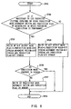
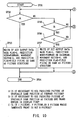
- This processing is the processing to generate a predicted picture output instead of a bit stream picture and the following four methods can be considered as the generation means.
- the first method is shown in steps SP32 and SP33, which uses a predicted picture at the spatially same position as a forward picture.
- the second method is shown in steps SP35 to SP37, which uses a predicted picture at the spatially same position as a picture one frame before in the display time.
- the third method uses a predicted picture obtained by using the prediction mode, movement vector, and prediction flag of a macroblock in which the preceding prediction is performed.
- the fourth method is shown in steps SP40 to SP42 and uses a predicted picture obtained by using the prediction mode, movement vector, and prediction flag of a processed macroblock.
- variable-length decoding circuit 18 starts processing from step SP31 in order to generate a predicted picture by any of the these four methods.
- the variable-length decoding circuit 18 determines whether or not to use a predicted picture at the spatially same position as a forward picture.
- variable-length decoding circuit 18 proceeds to step SP33 to set the DCT flag S9 to "1" and inhibit a picture from being output from a bit stream composed of the pseudo data and the like. Moreover, the variable-length decoding circuit 18 sets the prediction mode S6 to the forward prediction mode and a movement vector to zero. In this connection, the prediction flag S7 is fixed to a field or set the same as a picture structure is.
- variable-length decoding circuit 18 proceeds to step SP34 to terminate the processing.
- variable-length decoding circuit 18 proceeds to step SP35 to determine whether or not to generate a predicted picture by the second method. That is, the variable-length decoding circuit 18 determines whether or not to use a predicted picture at the spatially same position as a picture one frame before in the display time.
- variable-length decoding circuit 18 proceeds to step SP36 to determine whether the picture type of the picture to which the macroblock belongs is I-picture, P-picture, or B-picture whose preceding picture is not B-picture. In this case, if a negative result is obtained (that is, the picture preceding the picture to be decoded is B-picture), the variable-length decoding circuit 18 returns to step SP32 so as to retry the determination processing.
- step SP37 the processing of the variable-length decoding circuit 18 proceeds to step SP37 to inhibit the picture data obtained from the bit stream from being output and set the prediction mode S6 to the forward prediction side. Also in this case, the movement vector S5 is set to zero because the picture data at the spatially same position is used. Moreover, the prediction flag S7 is fixed to a field or uses a flag same as a picture structure. After these processings terminate, the processing is terminated at step SP34.
- variable-length decoding circuit 18 proceeds to step SP38 to determine whether or not to generate a predicted picture by the third method. That is, the variable-length decoding circuit 18 determines whether or not to use a predicted picture obtained by using the prediction mode, the movement vector, and the prediction flag of a macroblock in which the preceding prediction is performed.
- variable-length decoding circuit 18 proceeds to step SP39 to set the prediction mode S6, the movement vector S5, and the prediction flag S7 to the prediction mode, the movement vector, and the prediction flag stored in a memory, respectively.
- variable-length decoding circuit 18 proceeds to step SP40 to determine whether or not to generate a predicted picture by the fourth method: that is, the variable-length decoding circuit 18 determines whether or not to use a predicted picture obtained by using the prediction mode, the movement vector, and the prediction flag of a processed macroblock.
- variable-length decoding circuit 18 proceeds to step SP41 to determine whether or not the prediction mode is in a picture. If a negative result is obtained at step SP41, the variable-length decoding circuit 18 proceeds to step SP42 to set the prediction mode S6, the movement vector S5, and the prediction flag S7 read out of the header of the processed macroblock.
- variable-length decoding circuit 18 proceeds to step SP34 to terminate the processing of the present macroblock.
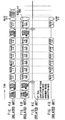
- a specific example of processing of the decoding circuit 16 is described in detail by referring to Figs. 11A to 11H.
- the macroblock "2" is interrupted by an error start code as shown in Figs. 11A and a bit stream in which data of the macroblock is uncompleted is input to the variable-length decoding circuit 18.
- the macroblock "1" includes the whole data from the block “1-1” to the block “1-6” and the macroblock data is completed.
- the block "2-2" is not completed and interrupted by the error start code D ES .
- variable-length decoding circuit 18 inputs the macroblock "1" in which a bit stream is present to the end.
- processing the macroblock header of the macroblock "1" enables the variable-length decoding circuit 18 to supply the DCT flag S8, the quantization scale S4, the prediction mode S6, the movement vector S5, and the prediction flag S7 to a rear-stage circuit, and moreover to supply the picture data to the inverse quantization circuit 19 whenever processing each block.
- variable-length decoding circuit 18 cannot detect that a bit stream is present to the end for the macroblock "1" until the processing of all blocks is terminated by processing the blocks "1-1" to "1-6" in order after the processing of the macroblock header "1" terminates. Therefore, it is not determined whether or not the data of the macroblock "1" can be supplied to a rear-stage circuit until the processing of all blocks of the macroblock "1" terminates, so that the variable-length decoding circuit 18 outputs various flags and data at the following timing.
- variable-length decoding circuit 18 writes the quantization scale S4 and the DCT flag S8 among the DCT flag S8, the quantization scale S4, the prediction mode S6, the movement vector S5, and the prediction flag S7 in the inverse quantization circuit 19 and the frame/field DCT block rearrangement circuit 22 when the processing of the macroblock header terminates.
- variable-length decoding circuit 18 start processing in each block to obtain the decoded picture of each block.
- the decoded picture data is directly supplied to the inverse quantization circuit 19.
- the inverse quantization circuit 19 and the IDCT circuit 21 at the rear stage operate assuming one block (8 pixels x 8 lines) as the unit, it is also possible to supply the picture data processed by the variable-length decoding circuit 18 to the inverse quantization circuit 19 through a memory circuit for a block.
- the inverse quantization circuit 19, the IDCT circuit 21, the frame/field DCT block rearrangement circuit 22 execute each processing whenever the picture data of each block is supplied as shown in Fig. 11D.
- variable-length decoding circuit 18 When the all processing of the macroblock "1" terminates, the variable-length decoding circuit 18 outputs the prediction mode S6, the movement vector S5, the prediction flag S7, and the mask flag S9, all of which are obtained by the macroblock header, to the movement compensation circuit section 20.
- the prediction mode S6, the movement vector S5, and the prediction flag S7 are output having the contents of the macroblock header "1" as it is.
- the mask flag S9 output from the variable-length decoding circuit 18 is designated to "0" (that is, no mask).
- the mask flag S9 is generated at the timing shown in Fig. 11E.
- the above-mentioned processes are the processings at steps SP1 to SP10.
- the movement compensation circuit section 20 executes decoding in accordance with these flags.
- the computing unit 23 receives the picture data through the inverse quantization circuit 19, the IDCT circuit 21, and the frame/field DCT block rearrangement circuit 22 at the timing shown in Fig. 11F.
- the time difference present between the input of the flags and the input of data to the computing unit 23 is a delay time required for the processing by the movement compensation circuit 24.
- the computing unit 23 adds the picture data S10 obtained from a bit stream and the predicted picture S11 read out of the movement compensation circuit 24 at the timing shown in Figs. 11F and 11G and outputs the addition result as the output reproduced picture S12.
- the designation of the mask flag S9 shows "absence of mask”
- both picture data S10 and S11 are added to the macroblock "1".
- the variable-length decoding circuit 18 detects an abnormal delimitation produced in a bit stream by the error start code D ES including a synchronous code.
- the error start code D ES is found in the middle of the processing of the block "2-2".
- variable-length decoding circuit 18 processes the macroblock header "2" and block "2-1" similarly to the case of the macroblock "1".
- the block "2-1" is not a pseudo data.
- variable-length decoding circuit 18 supplies the quantization scale S4 and the DCT flag S8 to a rear-stage circuit at the timing shown in Fig. 11C when the processing of the macroblock header "2" terminates similarly to the case of the macroblock "1". Then, the variable-length decoding circuit 18 processes the block "2-1" and supplies the picture data for the block "2-1" to the inverse quantization circuit 19.
- variable-length decoding circuit 18 finds the error start code while processing the block "2-2". At this time, the variable-length decoding circuit 18 generates a pseudo data for the remaining part of the macroblock "2" where a bit stream is broken so as to complete the macroblock "2" taking into consideration that the inverse quantization circuit 19 and the IDCT circuit 21 perform processing in blocks and the movement compensation circuit 24 performs processing in macroblocks. This state is shown in Fig. 11B.
- the pseudo data composed of a value such as zero is output to the inverse quantization circuit 19 as the remaining picture data of the block "2-2" in which the error start code is found and the picture data of remaining blocks "2-3", “2-4", "2-5", and "2-6".
- the picture data of the macroblock "2" is designated by the mask flag S9 so that it is not used for operation in the computing unit 23, it is possible to use any value except zero as the value of the pseudo data.
- the inverse quantization circuit 19, the IDCT circuit 21, and the frame/field DCT block rearrangement circuit 22 execute each processing in accordance with the picture data composed of the pseudo data, and supplies the processing results to the computing unit 23.
- the prediction mode S6, the movement vector S5, the prediction flag S7, and the mask flag S9 used in the movement compensation circuit 24 are output at the time when the whole processing of the macroblock "2" completes.
- the whole processing is defined as generation of pseudo data up to the block "2-6".
- Copying of the predicted picture is a processing performed by means of the prediction mode S6, the movement vector S5, the prediction flag S7, and the mask flag S8, and moreover using the movement compensation circuit 24 and the computing unit 23.
- the predicted picture S11 thus generated includes the predicted picture at the spatially same position as the forward picture as described in the previous section (steps SP32 to SP33), the predicted picture at the spatially same position as one frame before in the display time (steps SP35 to SP37), the predicted picture immediately before a macroblock interrupted by the error start code D ES and obtained by means of the prediction mode S6, the movement vector S5, and the prediction flag S7 of a macroblock being predicted (steps SP38 to SP39), and the predicted picture obtained by using the prediction mode S6, the movement vector S5, and the prediction flag S7 designated by a processed macroblock header (steps SP40 to SP42).
- variable-length decoding circuit 18 obtains the prediction mode S6, the movement vector S5, and the prediction flag S7 for obtaining these predicted pictures SV, and outputs them to the movement detection circuit 24. Moreover, in this case, the designation of the mask flag S9 shows "presence of mask” (that is, "1").
- the procedure is changed so as to generate a predicted picture by means of the prediction mode S6, the movement vector S5, and the prediction flag S7 of adjacent macroblock.
- the movement compensation circuit 24 generates a predicted picture according to the flags as shown in Fig. 11G. Moreover, the computing unit 23 adds and outputs the pseudo picture data S10 input through the inverse quantization circuit 19 or the like and the predicted picture S11 input from the movement compensation circuit 24. However, because "presence of mask" is designated by the mask flag S9, the picture data S10 is not used for calculation but the predicted picture S11 is directly output and serves as the output reproduced picture S12.
- this embodiment does not require any special timing control circuit for correctly operating the internal circuits. Therefore, it is not necessary to care about increase of the circuit scale.
- the error start code D ES uses a 32-bit code expressed by "00000000 00000000 0000 00000001 10110100".
- the present invention is not limited to this, but any code including a synchronous code can be used.
- the code length is not only limited to 32 bits, but a code with a length of more than 32 bits can be used.
- the operation of the decoding circuit 16 is avoided from damaging by inserting the error start code D ES into a bit stream.
- the present invention is not limited to this, but the error start code D ES can be used for other processing such as the special reproduction.
- discrete-cosine-transformed data is decoded at the time of encoding.
- the present invention is not limited to this, but also can widely be applied to decode orthogonally transformed data.
- a video signal input through a recording medium 3 or transmission line is decoded.
- the present invention is not limited to this, but also can be applied to decode an aural signal or a control signal in addition to the video signal.
- an uncorrectable error part of a digital signal or a data part including the uncorrectable error part is replaced with a special code including a synchronous code, and is output to the decoding means, so that it is possible to obtain a digital signal decoding apparatus which can confirm the presence of an error at the time of decoding and execute proper error processing.
- the decoding means outputs a predicted digital signal instead of a decoded signal of the uncompleted data group. Therefore, it is possible to obtain a digital signal decoding apparatus which can obtain an output signal not affected by the data group without adding a special circuit for processing the data group.
Landscapes
- Engineering & Computer Science (AREA)
- Signal Processing (AREA)
- Multimedia (AREA)
- Compression Or Coding Systems Of Tv Signals (AREA)
- Error Detection And Correction (AREA)
- Television Signal Processing For Recording (AREA)
- Compression, Expansion, Code Conversion, And Decoders (AREA)
- Image Processing (AREA)
Claims (10)
- Digitalsignal-Decodiervorrichtung (12), um ein codiertes digitales Videosignal, welches Makroblöcke aufweist, über einen Übertragungsweg zu empfangen, um ein Ausgangssignal von einem decodierten Signal des codierten digitalen Videosignals und eines vorhersagten digitalen Videosignals zu erzeugen, welche aufweist:eine Decodierverarbeitungseinrichtung (13) zum Ausgeben des vorhergesagten digitalen Videosignals anstelle des decodierten Signals für den gesamten Makroblock des Digitalsignals, wenn der Makroblock durch einen vorher bestimmten Fehlerstartcode abgegrenzt ist, der das Vorhandensein eines Fehlers im Digitalsignal zeigt und dadurch unvollständig ist.
- Digitalsignal-Decodiervorrichtung nach Anspruch 1, wobei
die Decodierverarbeitungseinrichtung (13) eine Variabel-Längen-Decodierschaltung (18) hat, und die Variabel-Längen-Decodierschaltung (18) verschiedene Flag-Signale, die verwendet werden, das Vorhersage-Digitalsignal zu erzeugen, zu einer Schaltung einer hinteren Stufe überträgt, wenn alle Verarbeitungen für den Makroblock beendet sind. - Digitalsignal-Decodiervorrichtung nach Anspruch 2, wobei
ein Ausgabeverbotsflag zum Verbieten der Verwendung des decodierten Signals des Digitalsignals in den verschiedenen Flag-Signalen enthalten ist. - Digitalsignal-Decodiervorrichtung nach Anspruch 3, wobei die Digitalsignal-Decodierschaltung (18) Pseudodaten in einen mangelhaften Teil des unvollständigen Makroblocks einfügt, so dass die Verarbeitung in einer Schaltung einer hinteren Stufe beendet wird, wenn der nichtvollständige Makroblock zugeführt wird.
- Digitalsignal-Decodiervorrichtung nach Anspruch 3, wobei:die Schaltung, welche in der hinteren Stufe der Variabel-Längen-Decodierschaltung (18) angeordnet ist, eine Berechnungsschaltung hat, um ein decodiertes Signal des Digitalsignals und des Vorhersage-Digitalsignals zu berechnen, um somit ein Ausgabesignal zu erzeugen, und die Berechnungsschaltung den Wert des decodierten Signals entsprechend dem Makroblock als null betrachtet, wenn die Verwendung des decodierten Signals durch das Ausgabeverbotsflag verboten wird.
- Digitalsignal-Decodiervorrichtung nach Anspruch 3, wobei:die Schaltung, welche in der hinteren Stufe der Variabel-Längen-Decodierschaltung (18) angeordnet ist, eine Berechnungsschaltung hat, um ein decodiertes Signal des Digitalsignals und des Vorhersage-Digitalsignals zu berechnen, um somit ein Ausgabesignal zu erzeugen, und die Berechnungsschaltung das decodierte Signal entsprechend dem Makroblock für den Betrieb nicht verwendet, wenn die Verwendung des decodierten Signals durch das Ausgabeverbotsflag verboten wird.
- Digitalsignal-Decodiervorrichtung nach Anspruch 1, wobei:das Vorhersage-Digitalsignal ein Bild an der räumlich gleichen Position wie ein Voraus-Bild ist.
- Digitalsignal-Decodiervorrichtung nach Anspruch 1, wobei:das Vorhersage-Digitalsignal ein Bild an der räumlich gleichen Position wie ein Vorhersage-Bild einen Rahmen vor dem Anzeigezeitpunkt ist.
- Digitalsignal-Decodiervorrichtung nach Anspruch 1, wobei:das Vorhersage-Digitalsignal ein Bild unmittelbar vor der unvollständigen Datengruppe ist, die durch den vorher festgelegten Code abgegrenzt ist, und mittels verschiedener Flag-Signale eines vorhergesagten Makroblocks erhalten wird.
- Digitalsignal-Decodiervorrichtung nach Anspruch 1, wobei:das vorhergesagte Digitalsignal ein Bild ist, welches mittels verschiedener Flag-Signale erhalten wird, die durch einen Datenkopf bestimmt werden, wenn der Prozess des Datenkopfteils des Makroblocks beendet ist.
Applications Claiming Priority (3)
| Application Number | Priority Date | Filing Date | Title |
|---|---|---|---|
| JP03003295A JP3518700B2 (ja) | 1995-01-25 | 1995-01-25 | デイジタル信号復号装置 |
| JP30032/95 | 1995-01-25 | ||
| JP3003295 | 1995-01-25 |
Publications (3)
| Publication Number | Publication Date |
|---|---|
| EP0724363A2 EP0724363A2 (de) | 1996-07-31 |
| EP0724363A3 EP0724363A3 (de) | 2000-09-27 |
| EP0724363B1 true EP0724363B1 (de) | 2006-05-24 |
Family
ID=12292487
Family Applications (1)
| Application Number | Title | Priority Date | Filing Date |
|---|---|---|---|
| EP19960300495 Expired - Lifetime EP0724363B1 (de) | 1995-01-25 | 1996-01-24 | Vorrichtung zur Dekodierung eines digitalen Signals |
Country Status (8)
| Country | Link |
|---|---|
| US (1) | US5714952A (de) |
| EP (1) | EP0724363B1 (de) |
| JP (1) | JP3518700B2 (de) |
| KR (1) | KR100420235B1 (de) |
| CN (1) | CN1166188C (de) |
| DE (1) | DE69636152T2 (de) |
| SG (1) | SG63538A1 (de) |
| TW (1) | TW303571B (de) |
Families Citing this family (26)
| Publication number | Priority date | Publication date | Assignee | Title |
|---|---|---|---|---|
| KR100377524B1 (ko) * | 1995-04-04 | 2003-07-23 | 마쯔시다덴기산교 가부시키가이샤 | 기록매체,기록방법과장치,및재생방법과장치 |
| JPH10112144A (ja) * | 1996-10-03 | 1998-04-28 | Sony Corp | 再生装置、誤り訂正装置及び誤り訂正方法 |
| JP3263625B2 (ja) * | 1997-03-28 | 2002-03-04 | 三洋電機株式会社 | デジタルビデオレコーダ |
| US6499060B1 (en) | 1999-03-12 | 2002-12-24 | Microsoft Corporation | Media coding for loss recovery with remotely predicted data units |
| JP2001357637A (ja) * | 2000-06-14 | 2001-12-26 | Sony Corp | 情報再生装置、情報処理方法及び情報記録媒体 |
| AU2001269125A1 (en) * | 2000-07-17 | 2002-01-30 | Koninklijke Philips Electronics N.V. | Coding of a data stream |
| US7372964B2 (en) | 2001-10-10 | 2008-05-13 | Kabushiki Kaisha Toshiba | Method and apparatus for recording information including secret information and method and apparatus for reproduction thereof |
| JP3688628B2 (ja) | 2001-11-09 | 2005-08-31 | 株式会社東芝 | 信号処理方法及び装置、信号再生方法及び装置、記録媒体 |
| JP3939136B2 (ja) * | 2001-11-28 | 2007-07-04 | 富士通株式会社 | 音声再生回路、デコード回路、音声再生装置及び音声再生方法 |
| KR100480051B1 (ko) * | 2002-06-17 | 2005-03-30 | 엘지전자 주식회사 | 영상신호 디코딩 방법 |
| JP2004080508A (ja) * | 2002-08-20 | 2004-03-11 | Nec Electronics Corp | 誤り訂正符号の復号方法、そのプログラム及びその装置 |
| US6973602B1 (en) * | 2002-09-05 | 2005-12-06 | Ciena Corporation | Link and path-level error performance monitoring |
| JP2005039480A (ja) * | 2003-07-18 | 2005-02-10 | Toshiba Corp | コンテンツ記録方法、記録媒体、コンテンツ記録装置 |
| US8085844B2 (en) * | 2003-09-07 | 2011-12-27 | Microsoft Corporation | Signaling reference frame distances |
| KR20050040448A (ko) * | 2003-10-28 | 2005-05-03 | 삼성전자주식회사 | 에러 검출 기능을 가진 비디오 디코딩방법과 이를 위한 장치 |
| JP4407472B2 (ja) * | 2004-10-29 | 2010-02-03 | ソニー株式会社 | 符号化及び復号装置並びに符号化及び復号方法 |
| US8634413B2 (en) | 2004-12-30 | 2014-01-21 | Microsoft Corporation | Use of frame caching to improve packet loss recovery |
| JP4848419B2 (ja) * | 2006-03-03 | 2011-12-28 | インターナショナル・ビジネス・マシーンズ・コーポレーション | 読み出しエラーを処理する読出装置、システム、その方法及びプログラム |
| JP2009111932A (ja) * | 2007-10-31 | 2009-05-21 | Panasonic Corp | 動画像復号化装置 |
| CN101488827B (zh) * | 2008-01-14 | 2015-07-08 | 华为技术有限公司 | 实现数据报错的方法和装置 |
| KR20100004792A (ko) * | 2008-07-04 | 2010-01-13 | 삼성전자주식회사 | 손상된 정보를 저장하는 방법, 손상된 정보를 저장할 수있는 정보 처리 장치, 손상된 정보를 저장 가능하게송신하는 정보 저장 장치, 손상된 정보를 저장하기 위한소프트웨어가 기록된, 정보 처리 장치로 읽을 수 있는 매체 |
| EP2141703B1 (de) * | 2008-07-04 | 2013-09-04 | Samsung Electronics Co., Ltd. | Verfahren und Vorrichtung zum Kopieren von Daten |
| TWI442778B (zh) * | 2010-02-05 | 2014-06-21 | Acer Inc | 視訊解碼裝置 |
| US9223643B2 (en) * | 2010-03-04 | 2015-12-29 | Microsoft Technology Licensing, Llc | Content interruptions |
| CN102890645B (zh) * | 2011-07-20 | 2015-11-25 | 群联电子股份有限公司 | 存储器储存装置、存储器控制器与数据写入方法 |
| WO2012092902A2 (zh) * | 2012-02-14 | 2012-07-12 | 华为技术有限公司 | 一种译码方法和译码装置 |
Family Cites Families (11)
| Publication number | Priority date | Publication date | Assignee | Title |
|---|---|---|---|---|
| JPH0498987A (ja) * | 1990-08-16 | 1992-03-31 | Matsushita Electric Ind Co Ltd | 誤り修整方法 |
| US5222069A (en) * | 1990-09-20 | 1993-06-22 | Ampex Systems Corporation | Miscorrection arrangement for the concealment of misdetected or miscorrected digital signals |
| EP0482888B1 (de) * | 1990-10-25 | 1997-06-04 | Matsushita Electric Industrial Co., Ltd. | Aufzeichnungs- und Wiedergabegerät für Videosignale |
| US5488418A (en) * | 1991-04-10 | 1996-01-30 | Mitsubishi Denki Kabushiki Kaisha | Encoder and decoder |
| JPH04358486A (ja) * | 1991-06-04 | 1992-12-11 | Toshiba Corp | 高能率符号化信号処理装置 |
| US5416804A (en) * | 1991-08-21 | 1995-05-16 | U.S. Philips Corporation | Digital signal decoder using concatenated codes |
| JP2706398B2 (ja) * | 1992-02-14 | 1998-01-28 | シャープ株式会社 | 映像信号のディジタル記録装置及び再生装置 |
| JPH0698313A (ja) * | 1992-09-14 | 1994-04-08 | Sony Corp | 動画像復号化装置 |
| JP3158740B2 (ja) * | 1992-11-20 | 2001-04-23 | ソニー株式会社 | ディジタルビデオ信号の送信方法及びダビング方法 |
| JPH06325503A (ja) * | 1993-05-11 | 1994-11-25 | Matsushita Electric Ind Co Ltd | ディジタルデータの処理方法 |
| US5576765A (en) * | 1994-03-17 | 1996-11-19 | International Business Machines, Corporation | Video decoder |
-
1995
- 1995-01-25 JP JP03003295A patent/JP3518700B2/ja not_active Expired - Lifetime
-
1996
- 1996-01-22 US US08/589,460 patent/US5714952A/en not_active Expired - Lifetime
- 1996-01-23 TW TW85100788A patent/TW303571B/zh not_active IP Right Cessation
- 1996-01-24 EP EP19960300495 patent/EP0724363B1/de not_active Expired - Lifetime
- 1996-01-24 SG SG1996000429A patent/SG63538A1/en unknown
- 1996-01-24 DE DE1996636152 patent/DE69636152T2/de not_active Expired - Lifetime
- 1996-01-25 KR KR1019960001566A patent/KR100420235B1/ko not_active IP Right Cessation
- 1996-01-25 CN CNB961014520A patent/CN1166188C/zh not_active Expired - Lifetime
Also Published As
| Publication number | Publication date |
|---|---|
| CN1153440A (zh) | 1997-07-02 |
| US5714952A (en) | 1998-02-03 |
| JP3518700B2 (ja) | 2004-04-12 |
| DE69636152T2 (de) | 2007-05-03 |
| SG63538A1 (en) | 1999-03-30 |
| EP0724363A2 (de) | 1996-07-31 |
| CN1166188C (zh) | 2004-09-08 |
| EP0724363A3 (de) | 2000-09-27 |
| TW303571B (de) | 1997-04-21 |
| DE69636152D1 (de) | 2006-06-29 |
| KR960030710A (ko) | 1996-08-17 |
| KR100420235B1 (ko) | 2004-05-22 |
| JPH08204584A (ja) | 1996-08-09 |
Similar Documents
| Publication | Publication Date | Title |
|---|---|---|
| EP0724363B1 (de) | Vorrichtung zur Dekodierung eines digitalen Signals | |
| KR960002393B1 (ko) | 영상신호기록재생장치 | |
| US5148271A (en) | Method for transmission of variable length code and apparatus for coding a video signal | |
| EP0702879B1 (de) | Aufzeichnung und wiedergabe eines mpeg-informationssignals auf einen/von einem aufzeichnungsträger | |
| EP0627853B1 (de) | Gerät zur Wiedergabe von Bildern und Gerät zur Dekodierung von Bildern | |
| USRE42455E1 (en) | Moving-picture signal coding and/or decoding system resistant to transmission error | |
| EP0590974A2 (de) | Editiergerät für kodierte Daten und Dekodiergerät für editierte kodierte Daten | |
| RU2229174C2 (ru) | Запись информационных сигналов в формате mpeg на носитель информации и их воспроизведение | |
| EP0575997B1 (de) | Vorrichtung zum Verarbeiten des Signals eines digitalen Videocassettenrecorders | |
| EP0602817B1 (de) | Vorrichtung zum Verarbeiten eines digitalen Videosignals | |
| US20010040903A1 (en) | Multiplexing apparatus and method, transmitting apparatus and method, and recording medium | |
| US5970207A (en) | Television system for transmitting pictures in a digital form | |
| US6275618B1 (en) | Apparatus for and method of processing images | |
| EP0644691A2 (de) | Gerät zur Aufzeichnung und Wiedergabe eines komprimierten Videosignals | |
| US5740187A (en) | Data processing using interpolation of first and second information based on different criteria | |
| US5544176A (en) | Information recording apparatus which eliminates unnecessary data before recording | |
| US5881070A (en) | Variable length coding apparatus | |
| JP2001157204A (ja) | 動画像復号化方法及び装置 | |
| JPH07176144A (ja) | パケット変換装置及びパケット変換方式 | |
| EP0660606A1 (de) | Verfahren und vorrichtung zur bildsignaldekodierung | |
| JP3357468B2 (ja) | 画像圧縮システムおよび画像再生システム | |
| US5838925A (en) | Method and apparatus for transmission of compressed picture data | |
| US6983101B1 (en) | Image recording apparatus, image reproducing apparatus and image recording/reproducing apparatus | |
| JP3854697B2 (ja) | 受信装置 | |
| EP0578308B1 (de) | Fernsehsystem zur Übertragung von Bildern in digitaler Form |
Legal Events
| Date | Code | Title | Description |
|---|---|---|---|
| PUAI | Public reference made under article 153(3) epc to a published international application that has entered the european phase |
Free format text: ORIGINAL CODE: 0009012 |
|
| AK | Designated contracting states |
Kind code of ref document: A2 Designated state(s): DE FR GB |
|
| PUAL | Search report despatched |
Free format text: ORIGINAL CODE: 0009013 |
|
| AK | Designated contracting states |
Kind code of ref document: A3 Designated state(s): DE FR GB |
|
| 17P | Request for examination filed |
Effective date: 20010309 |
|
| 17Q | First examination report despatched |
Effective date: 20041228 |
|
| GRAP | Despatch of communication of intention to grant a patent |
Free format text: ORIGINAL CODE: EPIDOSNIGR1 |
|
| GRAS | Grant fee paid |
Free format text: ORIGINAL CODE: EPIDOSNIGR3 |
|
| GRAA | (expected) grant |
Free format text: ORIGINAL CODE: 0009210 |
|
| AK | Designated contracting states |
Kind code of ref document: B1 Designated state(s): DE FR GB |
|
| REG | Reference to a national code |
Ref country code: GB Ref legal event code: FG4D |
|
| REF | Corresponds to: |
Ref document number: 69636152 Country of ref document: DE Date of ref document: 20060629 Kind code of ref document: P |
|
| ET | Fr: translation filed | ||
| PLBE | No opposition filed within time limit |
Free format text: ORIGINAL CODE: 0009261 |
|
| STAA | Information on the status of an ep patent application or granted ep patent |
Free format text: STATUS: NO OPPOSITION FILED WITHIN TIME LIMIT |
|
| 26N | No opposition filed |
Effective date: 20070227 |
|
| REG | Reference to a national code |
Ref country code: GB Ref legal event code: 746 Effective date: 20120703 |
|
| REG | Reference to a national code |
Ref country code: DE Ref legal event code: R084 Ref document number: 69636152 Country of ref document: DE Effective date: 20120614 |
|
| PGFP | Annual fee paid to national office [announced via postgrant information from national office to epo] |
Ref country code: DE Payment date: 20140122 Year of fee payment: 19 |
|
| PGFP | Annual fee paid to national office [announced via postgrant information from national office to epo] |
Ref country code: FR Payment date: 20140123 Year of fee payment: 19 |
|
| PGFP | Annual fee paid to national office [announced via postgrant information from national office to epo] |
Ref country code: GB Payment date: 20140121 Year of fee payment: 19 |
|
| REG | Reference to a national code |
Ref country code: DE Ref legal event code: R119 Ref document number: 69636152 Country of ref document: DE |
|
| GBPC | Gb: european patent ceased through non-payment of renewal fee |
Effective date: 20150124 |
|
| PG25 | Lapsed in a contracting state [announced via postgrant information from national office to epo] |
Ref country code: DE Free format text: LAPSE BECAUSE OF NON-PAYMENT OF DUE FEES Effective date: 20150801 Ref country code: GB Free format text: LAPSE BECAUSE OF NON-PAYMENT OF DUE FEES Effective date: 20150124 |
|
| REG | Reference to a national code |
Ref country code: FR Ref legal event code: ST Effective date: 20150930 |
|
| PG25 | Lapsed in a contracting state [announced via postgrant information from national office to epo] |
Ref country code: FR Free format text: LAPSE BECAUSE OF NON-PAYMENT OF DUE FEES Effective date: 20150202 |