EP0723249A2 - Système de transmission d'image avec appareil pour mettre une grille - Google Patents
Système de transmission d'image avec appareil pour mettre une grille Download PDFInfo
- Publication number
- EP0723249A2 EP0723249A2 EP96300404A EP96300404A EP0723249A2 EP 0723249 A2 EP0723249 A2 EP 0723249A2 EP 96300404 A EP96300404 A EP 96300404A EP 96300404 A EP96300404 A EP 96300404A EP 0723249 A2 EP0723249 A2 EP 0723249A2
- Authority
- EP
- European Patent Office
- Prior art keywords
- mesh
- image
- image data
- subject
- memory
- Prior art date
- Legal status (The legal status is an assumption and is not a legal conclusion. Google has not performed a legal analysis and makes no representation as to the accuracy of the status listed.)
- Withdrawn
Links
Images


Classifications
-
- H—ELECTRICITY
- H04—ELECTRIC COMMUNICATION TECHNIQUE
- H04N—PICTORIAL COMMUNICATION, e.g. TELEVISION
- H04N1/00—Scanning, transmission or reproduction of documents or the like, e.g. facsimile transmission; Details thereof
- H04N1/387—Composing, repositioning or otherwise geometrically modifying originals
-
- G—PHYSICS
- G06—COMPUTING; CALCULATING OR COUNTING
- G06T—IMAGE DATA PROCESSING OR GENERATION, IN GENERAL
- G06T11/00—2D [Two Dimensional] image generation
-
- H—ELECTRICITY
- H04—ELECTRIC COMMUNICATION TECHNIQUE
- H04N—PICTORIAL COMMUNICATION, e.g. TELEVISION
- H04N1/00—Scanning, transmission or reproduction of documents or the like, e.g. facsimile transmission; Details thereof
- H04N1/42—Systems for two-way working, e.g. conference systems
Definitions
- the present invention relates to an image transmission device and an image transmission system. More particularly, the present invention relates to an image transmission device and a system utilizing the image transmission device to transmit images photographed by a television camera, such as a CCD camera, to remote locations, and to observe the same image at multiple separate locations.
- a television camera such as a CCD camera
- Devices which allow a person at a remote location to observe an image of a subject transmitted from another location.
- devices which allow specialists at remote locations to observe a pathological examination by transmitting a subject image to the remote locations.
- the subject image is displayed on a television monitor at the location from which the subject image is transmitted (transmission location) and the subject image is also displayed at the remote location (reception location).
- the image displayed on the respective television monitors can then be discussed via telephone.
- an arrow-like indicator which is manipulated using a mouse is synthesized on the image of the subject in the television monitor.
- by displaying the tracks of the arrow-like indicator it becomes possible to indicate a part of a subject which should be cut, or to clearly designate a necessary range while discussing a subject.
- an image communication system for displaying a subject image produced by a camera unit, having an image transmission device to form mesh image data representing a mesh image and to synthesize the mesh image data with subject image data representing the image of the subject to form synthesized image data for transmission.
- an image communication system including a television camera to produce subject image data representing a subject image.
- the subject image data produced by the television camera is stored in an image data memory.
- a mesh setting device sets a mesh image comprised of multiple parallel and equidistant straight lines to be superimposed on the subject image.
- the mesh setting device sets a distance between the straight lines, a number of the straight lines and an angle of inclination of the straight lines comprising the mesh image.
- the mesh image data forming the mesh image is stored in a mesh memory, and an image synthesis device synthesizes the image data stored by the mesh memory and the image data stored by the image data memory.
- the synthesized image data is displayed on a television monitor locally, and is transmitted to a remote location to be displayed at the remote location.
- an image communication system including a television camera to produce subject image data representing a subject image wherein the subject image is to be displayed locally and remotely by the image communication system.
- the image communication system also includes a first communication device having a first data image memory to store the subject image data produced by the television camera, a first mesh setting input device to form mesh image data comprising parallel and equidistant straight lines, wherein the number of straight lines, the distance between the straight lines and the angle of inclination of the straight lines are optionally set, a first mesh memory to store the mesh image data set by the mesh setting input device, a first image synthesis device to synthesize the mesh image data stored by the mesh memory and the subject image data stored by the image memory, a first television monitor to receive the synthesized image data and to display an image corresponding to the synthesized image data, and a first transmission control device to transmit the synthesized image data.
- the image communication system also includes a second communication device to receive the synthesized image data transmitted from the first communication device, the second communication device including a second transmission control device to receive the synthesized image data from the first transmission control device, and a second television monitor to display an image corresponding to the image data received by the second transmission device.
- the second communication device may also include a second image data memory to store the subject image data, a second mesh memory to store the mesh image data, a second mesh setting input device to form mesh image data comprising parallel and equidistant straight lines, and a second image synthesis device to synthesize image data stored by the second mesh memory and the second image data memory, wherein the mesh image displayed on the first and second television monitors is settable by any one of the first mesh setting input device and the second mesh setting input device.
- an image communication system including a camera to produce subject image data representing a subject image, and a first communication device to transmit the subject image data.
- the first communication device including a first image memory to store the subject image data, and a first transmission control device to transmit the subject image data.
- a first television monitor displays the subject image.
- the image communication system also includes a second communication device to receive the subject image data transmitted from the first transmission control device.
- the second communication device includes a second image memory to store the subject image data received by the second communication device, a first mesh setting device to form mesh image data comprising parallel and equidistant straight lines, a first mesh memory to store the mesh image data formed by the first mesh setting device, a first image synthesis device to synthesize the image data stored by the first mesh memory and the image data stored by the second image memory, and a second transmission control device to transmit the synthesized image data to the first communication device.
- a second television monitor receives the synthesized image data from the first image synthesis device and displays a synthesized image.
- the synthesized image is also transmitted to the first communication device via the second transmission control device to display the synthesized image on the first television monitor.
- the first communication device may also comprise a second mesh memory for storing mesh image data transmitted from the first mesh setting device, and a second image synthesis device to synthesize the mesh image data stored in the second mesh memory with the subject image data stored in the first image memory.
- an image communication system to transmit a subject image to a remote location, comprising a camera unit to form subject image data representing a subject image, an image memory to store the subject image data, a mesh setting device to set mesh image data to form a mesh image, a mesh memory to store the mesh image data set by the mesh setting device, an image synthesis circuit to synthesize the mesh image data and the subject image data to form a synthesized image, a transmission device to transmit the synthesized image, and a television monitor to display an image corresponding to the synthesized image data.
- the mesh setting device may comprise a first mesh input switch at a subject image transmission location to set mesh setting information to set the mesh image data, a first mesh control circuit at the subject image transmission location to form mesh image data based on the mesh setting information set by the first mesh input switch, and a second mesh control circuit at a subject image reception location to form mesh image data based on the mesh setting information set by the first mesh input switch.
- the mesh setting device may comprise a first mesh setting device at a subject image transmission location to set the mesh image data and a second mesh setting device at a subject image reception location to set the mesh image data, wherein the first and second mesh setting devices independently set the mesh image data.
- the mesh setting device may also comprise a first mesh input switch at a subject image reception location to set mesh setting information to set the mesh image data, a first mesh control circuit at the subject image reception location to form mesh image data based on the mesh setting information set by the first mesh input switch, and a second mesh control circuit at a subject image reception location to form mesh image data based on the mesh setting information set by the first mesh input switch.
- the mesh setting device in accordance with embodiments of the present invention includes a mesh input switch to set mesh setting information for setting mesh image data comprising multiple parallel and equidistant straight lines, including the number of straight lines, the distance between the straight lines and the angle of inclination of the straight lines.
- the mesh setting device also includes a mesh control circuit to form the mesh image data in accordance with the mesh setting information set by the mesh input switch.
- the mesh setting information may also include an ordered code associated with respective straight lines comprising the mesh.
- FIG. 1 is a block diagram of an image transmission system in accordance with a first embodiment of the present invention.
- FIGS. 2A-2C are diagrams showing the synthesis of subject image data and mesh image data in accordance with embodiments of the present invention.
- FIG. 3 is a diagram showing the external appearance of the mesh input switch in accordance with embodiments of the present invention.
- FIG. 4 is a block diagram of an image transmission system in accordance with a second embodiment of the present invention.
- FIG. 5 is a block diagram of an image transmission system in accordance with a third embodiment of the present invention.
- FIG. 6 is a block diagram of an image transmission system in accordance with a fourth embodiment of the present invention.
- FIG. 7 is a block diagram of an image transmission system in accordance with a fifth embodiment of the present invention.
- FIG. 8 is a block diagram of an image transmission system in accordance with a sixth embodiment of the present invention.
- FIG. 1 is a block diagram of an image transmission system in accordance with a first embodiment of the present invention.
- a camera unit 11 at a location from which a subject image is transmitted, and having a device for converting optical image signals into analog image signals, such as a charge coupled device (CCD), outputs analog image signals representing the subject image to a camera control unit (CCU) 15.
- the analog image signals from the CCU 15 are input to an image transmission device 20.
- the analog image signals received from the camera control unit 15 are converted to digital image data by an analog-to-digital (A/D) converter 21 in the image transmission device 20.
- the digital image data from the A/D converter 21 is then stored in an image memory 23 for image data storage.
- the image data stored in the image memory 23 is transmitted, via a transmission control device 25, to a transmission device 50 at a remote location (hereinafter referred to as "reception location") using a telephone circuit, such as an integrated services digital network (ISDN).
- ISDN integrated services digital network
- FIG. 2B shows an example of an image produced from digital image data stored in image memory 23, as described above.
- the image transmission device 20 also includes an input control device 31 for entering mesh data settings.
- the mesh data is image data representing multiple straight lines that are parallel and equidistant.
- the input control device 31 comprises a mesh input switch 32 and a mesh control circuit 38, described in more detail below.
- the image transmission device 20 includes a mesh memory 41 for storing the mesh image data set by the input control device 31; an image synthesis circuit 45 which forms a synthesized image signal by combining the mesh image data stored in memory 41 and the subject image data stored in image memory 23; a digital-to-analog converter 27, and a television monitor 29 to display the synthesized image.
- FIG. 2A shows an example of the mesh image data stored in mesh memory 41. As shown in FIG. 2A, the mesh image data is for the purpose of displaying multiple parallel and equidistant straight lines.
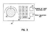
- the mesh input switch 32 will now be described in more detail with reference to FIG. 3.
- the mesh input switch 32 includes an inclination setting knob 33, a line number selection key 34, a pitch selection key 35 and a ten key input device 36.
- information for setting the mesh is transmitted from the mesh input switch 32 to the mesh control circuit 38.
- the mesh control circuit 38 forms digital image data based on the mesh setting information optionally set by the mesh input switch 32.
- the inclination setting knob 33 changes the inclination of the parallel lines which comprise the mesh according to the rotational angle of the knob 33. Specifically, the inclination of the parallel lines forming the mesh are changed by rotating the inclination setting knob 33 by a specified rotational angle which corresponds to the amount of inclination of the mesh parallel lines.
- the mesh displayed on the television monitor can have a right inclination, as shown in FIG. 2A, or a left inclination (not shown in the figure) by rotating the inclination setting knob 33.
- the ten key input device 36 sets the number of the lines in the mesh.
- the mesh control circuit 38 By manipulating a line number selection key 34 while setting the number of lines using the ten key input device 36, the mesh control circuit 38 forms image data for displaying a number of equidistant straight lines equivalent to the numeric value set by the ten key input device 36, and which have an inclination corresponding to the rotational angle of inclination setting knob 33.
- the distance between lines specifically, the pitch, can be adjusted.
- the mesh control circuit 38 forms image data for displaying the parallel straight lines of the mesh having an inclination corresponding to the rotational angle of the inclination setting knob 33 and a distance between lines corresponding to the numeric value entered by ten key input device 36.
- the mesh image data formed by mesh control circuit 38 is stored in mesh data memory 41.
- the image synthesis circuit 45 receives mesh image data from the mesh memory 41 and subject image data from the image memory 23 and creates image signals by synthesizing the mesh image data and the subject image data.
- the synthesized image data is converted by D/A converter 27 into analog image signals.
- the analog image signals from D/A/ converter 27 are displayed by television monitor 29 to display an image which superimposes multiple straight lines arranged in parallel at equal distances on the image of the subject that is photographed by camera unit 11.
- FIG. 2C shows an example of a synthesized image.
- the synthesized image signals are transmitted by the transmission control device 25 to the transmission device 50 at the reception location.
- the synthesized image data received by the transmission device 50 at the reception location passes through a transmission control device 51 and is stored in an image memory 53. Further, the synthesized image data that passes through the transmission control device 51 is converted by a D/A converter 55 into analog image signals which can be displayed on a television monitor 57.
- the subject image on which the mesh is superimposed can be seen on the television monitor 57 at the reception location in the same manner as it is seen on the television monitor 29 at the image transmission location.
- the same image can be viewed at both the image transmission location and image reception location, and discussion of the displayed image can be conducted via telephone 70, or other communication devices, at the transmission and reception locations.
- Locations on the subject for example, a location can be suitably specified based on the straight lines comprising the mesh which are superimposed over the displayed subject image.
- image data including codes can be formed by the mesh control circuit 38 to display an alphabetic code (A, B, C, etc.%) or numeric code, or any similar identifying code, associated with the straight lines comprising the mesh.
- the direct connection between the transmitting location and the reception location is not limited to telephone circuits such as ISDN, and other suitable circuits, such as custom communication circuits may also be used.
- custom communication circuits the transmission control device 25 of the transmission location and the transmission control device 51 of the reception location are joined to the communications circuit.
- the mesh when the image of the subject is displayed on the television monitor, multiple parallel and equidistant straight lines (the mesh) are superimposed on the subject image on the television monitor screen.
- the inclination of the mesh lines, the number of mesh lines and the distance between the mesh lines can be set and easily modified, allowing a subject location, such as a cut location, to be suitably indicated.
- an image having the same superimposed mesh can be displayed on television monitors at the transmission location and reception location, and the directions and confirmation of the subject cut location can be suitably conducted.
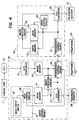
- FIG. 4 is a block diagram of an image transmission system in accordance with a second embodiment of the present invention. Like elements in the first and second embodiments are referred to by like reference numerals.
- an output of the input control device 31 is passed directly to the transmission control device 25 and is sent to transmission device 50 at the reception location.
- the mesh setting information from input control device 31 which stipulates the distance between, the number of and the angle of inclination of the mesh straight lines are thereby transmitted directly to the subject image reception location.
- the image transmission device 50 at the reception location includes a mesh memory 61 for storing the mesh information, a mesh control circuit 63, and an image synthesis circuit 65 in the same manner as the image transmission device 20 at the transmission location. Accordingly, if the inclination of the mesh, the pitch, or the number of lines has been modified by the input control device 31 at the transmission location, it is possible to transmit only the mesh setting information to the reception location. By transmitting only the modified mesh setting information to the reception location without also transmitting the image data, the mesh may be modified quickly. Specifically, since the mesh setting information involves an extremely small amount of data in comparison with the amount of image data, the mesh data may be modified and transmitted quickly to the reception location without transmitting the synthesized subject image data and mesh image data.
- the transmitted mesh setting information is input into the mesh control circuit 63 to form the mesh image data.
- the mesh image data formed by mesh control circuit 63 is stored in a mesh memory 61.
- the image data stored in frame memory 23 at the transmission location has already been transmitted and stored in image memory 53.
- the image synthesis circuit 65 synthesizes the subject image data stored in image memory 53 and the mesh image data stored in mesh memory 61.
- the synthesized image data passes through D/A converter 55, and is displayed on television monitor 57.
- the same mesh is superimposed on the subject image at the reception location and at the transmission location and displayed on television monitor 29 at the transmission location and television monitor 57 at the reception location.
- the mesh setting modifications at the transmission location are immediately transmitted to the reception location so that the modified mesh is immediately superimposed on the subject image at the reception location.
- discussions regarding a subject image can be conducted efficiently and instructions given without delay.
- the second embodiment of the present invention provides the advantage that the instructions regarding the cut location and the direction of the cut can be suitably and quickly conducted when, for example, slicing the subject which comprises one part of an extracted organ and creating a specimen of the subject material.
- the image transmission system with a device to detect the distance between a table on which the camera unit 11 is mounted and the subject, and to detect the zoom of the lens of camera unit 11, when designating the pitch of the mesh, it is possible to set the input pitch number to correspond to the actual dimensions of the image that is photographed. By designating the pitch of the mesh to correspond to the dimensions of the photographed image, the size of the subject can also be determined using the mesh. If the distance between the table on which camera unit 11 is mounted and the subject is fixed, a device to detect the distance between the table and the subject is not necessary.
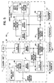
- FIG. 5 is a block diagram of an image transmission device in accordance with a third embodiment of the present invention.
- Like reference numerals in the first, second and third embodiments refer to like elements.
- the transmission device 50 at the reception location is provided with an input control device 69 which is the same as the input control device 31 of image transmission device 20 at the transmission location.
- the mesh setting information may be input and modified at either of the transmission or reception location.
- the input control device 69 includes a mesh input switch 68 to input, at the reception location, the mesh setting information, and a mesh control circuit 63 to set the mesh setting information.
- the mesh control circuit 63 passes the mesh setting information to the transmission control device 51 where it is transmitted to the transmission control device 25 at the transmission location and then to the mesh control circuit 38.
- the mesh setting information set at the transmission location is input into the mesh control circuit 63 at the reception location. Because respective input control devices 31 and 69 are provided at the transmission and reception location, the mesh inclination and distance between mesh lines can be suitably adjusted at either the transmission location or the reception location, and even more effective study and discussion can be conducted.
- the image transmission device in accordance with the third embodiment of the present invention has the advantage of being extremely effective during long distance diagnoses, and, in particular, long distance pathological diagnoses.
- a part to be diagnosed at the remote location (reception location), which may have a size of about up to the first joint of the little finger, is cut out in an operating room at the transmission location.
- the extracted part is photographed by the CCD camera unit 11 and the image is transmitted to the remote location.
- a specialist doctor at the remote location gives directions on the slice position and direction with respect to the part to be diagnosed in order to make a microscope specimen.
- the specialist doctor at the remote location set the mesh at this time using the embodiment of the present invention shown in FIG. 5, the position and direction to be sliced can be suitably instructed while confirming the location that should be pathologically determined.
- accurate directions can be given.
- the images are taken by superimposing a fixed indicator (object), such as a grid scale of a fixed dimension, onto the subject, and an image could be created in which the scale and the subject are synthesized. Nonetheless, the parts which are cut out during actual surgery vary in size, and it is difficult to mount the subject in the field of vision of camera unit 11 such that the scale direction and the direction to be sliced agree.
- a fixed indicator object
- the parts which are cut out during actual surgery vary in size, and it is difficult to mount the subject in the field of vision of camera unit 11 such that the scale direction and the direction to be sliced agree.
- the subject may be positioned in the visual field of camera unit 11 when the subject is photographed without paying attention to the direction of the extracted part and the direction of the camera for the purpose of preparing the specimen.
- the location to be cut can be suitably indicated on the image by changing the angle of inclination of the lines comprising the mesh, the distance between the lines and the number of lines.
- the slice position and direction for a subject can be transmitted to the remote location.
- the specimen is normally sliced and prepared such that a part which is cut out is cut and divided following a given direction, for example, the direction of the mesh.
- the mesh in accordance with the embodiments of the present invention fully provides the necessary function as an index for indicating the position and direction of a cut.
- the same image can be observed at the transmission location and the reception location, and the inclination of the lines and the distance between the lines which comprise the mesh that is synthesized with the subject image can be optionally set from both the transmission location and the reception location based on the observed image.
- FIG. 6 is a block diagram of an image transmission system in accordance with a fourth embodiment of the present invention. Like elements in the first, second, third and fourth embodiments are referred to by like reference numerals.
- the transmission device 50 at the reception location includes input control circuit 69 and the image transmission device 20 at the transmission location includes only mesh control circuit 38, with the mesh input switch omitted. As a result, the mesh cannot be set at the transmission location.
- an image transmission system in which the system at an operating room side (transmission location) is configured inexpensively because the mesh input switch is omitted. Further, since the mesh is set by a pathologist at the reception location, who can perform a more accurate diagnosis, effective setting of the mesh can be made.
- the image transmission device at the transmission location can be simplified, and the system at the transmission location (operating room side) can be configured inexpensively.
- the cut location is indicated by setting the inclination angle and distance between the lines of the mesh only at the reception location where a more precise diagnosis can be made.
- FIG. 7 is a block diagram of an image transmission system in accordance with a fifth embodiment of the present invention. Like elements in the first, second, third, fourth and fifth embodiments are referred to by like reference numerals.
- mesh control circuit 38 of image transmission device 20 at the transmission location is omitted from the fourth embodiment shown in FIG. 6.
- the configuration of image transmission device 20 shown in FIG. 7 is even more simplified than that of the image transmission device shown in FIG. 6.
- the mesh image data that is formed by input control device 69 provided in transmission device 50 at the reception location is stored in mesh memory 61.
- the mesh image data formed by input control circuit 69 is also sent to the image transmission device 20 at the transmission location, and is stored in mesh memory 41 at the transmission location.
- the same mesh image data is stored in the mesh memories 41 and 61 at the transmission location and the reception location, respectively.
- the mesh image data is sent to the remote location without mesh setting information.
- the mesh image data is a larger volume of data compared to the mesh setting information data, but the mesh image data is a smaller volume of data than the synthesized image data of the subject image and the mesh image.
- the transmission time can be shortened compared to transmitting the synthesized image data. For this reason, if the mesh settings have been modified at the reception location, the synthesized image can be immediately displayed at the transmission location by transmitting only the mesh image data to the transmission location, and, in addition, the costs of communication can also be controlled.
- FIG. 8 is a block diagram of an image transmission system in accordance with a sixth embodiment of the present invention. Like elements in the first, second, third, fourth, fifth, and sixth embodiments are referred to by the same reference numerals.
- the mesh memory 41 and the image synthesis circuit 45 at the transmission location are omitted from the configuration of the image transmission device 20 in the embodiment shown in FIG. 7, and an image memory 48 is provided at the transmission location.
- the sixth embodiment of the present invention is particularly advantageous if the transmission volume of the communications circuit is large, and it is possible to transmit images having a great volume of data in a short period of time.
- the image data which has been stored in image memory 23 of image transmission device 20 is transmitted to transmission device 50 at the reception location, and stored in image memory 53.
- the mesh image data and the transmitted image data are synthesized by image synthesis circuit 65 of transmission device 50.
- the synthesized image data is returned to image transmission device 20 at the transmission location, and is stored in image memory 48.
- the same image can be monitored at both the transmission location and the reception location.
- the image transmission device 20 in accordance with the sixth embodiment shown in FIG. 8 is even more simplified than the image transmission device shown in FIG. 7.
- the image transmission device 20 in accordance with the embodiments of the present invention, has been described as including an A/D converter 21 to convert the analog signals from camera control unit 15 into digital signals
- the present invention is not limited to using an A/D converter.
- the A/D converter 21 is not necessary.
- a monitor which can input digital image signals is utilized to display the image at the transmission and reception locations, digital-to-analog converters 27 and 55 are not necessary.
Applications Claiming Priority (2)
| Application Number | Priority Date | Filing Date | Title |
|---|---|---|---|
| JP7007795A JPH08205126A (ja) | 1995-01-23 | 1995-01-23 | 画像伝送装置及び画像伝送システム |
| JP7795/95 | 1995-01-23 |
Publications (2)
| Publication Number | Publication Date |
|---|---|
| EP0723249A2 true EP0723249A2 (fr) | 1996-07-24 |
| EP0723249A3 EP0723249A3 (fr) | 1997-04-09 |
Family
ID=11675588
Family Applications (1)
| Application Number | Title | Priority Date | Filing Date |
|---|---|---|---|
| EP96300404A Withdrawn EP0723249A3 (fr) | 1995-01-23 | 1996-01-22 | Système de transmission d'image avec appareil pour mettre une grille |
Country Status (3)
| Country | Link |
|---|---|
| US (1) | US6005637A (fr) |
| EP (1) | EP0723249A3 (fr) |
| JP (1) | JPH08205126A (fr) |
Families Citing this family (5)
| Publication number | Priority date | Publication date | Assignee | Title |
|---|---|---|---|---|
| US20040085443A1 (en) * | 2000-12-13 | 2004-05-06 | Kallioniemi Olli P | Method and system for processing regions of interest for objects comprising biological material |
| JP4346938B2 (ja) * | 2003-04-09 | 2009-10-21 | キヤノン株式会社 | 画像処理装置、方法、プログラム及び記憶媒体 |
| JP4756892B2 (ja) * | 2005-04-01 | 2011-08-24 | キヤノン株式会社 | 画像処理装置 |
| EP1718065A1 (fr) * | 2005-04-30 | 2006-11-02 | STMicroelectronics (Research & Development) Limited | Methode et appareil pour le traitement de données d'images |
| JP4817930B2 (ja) * | 2006-03-31 | 2011-11-16 | キヤノン株式会社 | 印刷制御装置、制御方法、及びプログラム |
Citations (5)
| Publication number | Priority date | Publication date | Assignee | Title |
|---|---|---|---|---|
| GB2151100A (en) * | 1983-11-29 | 1985-07-10 | Yokogawa Medical Syst | Composite image display system for computerized tomographs and other image data |
| FR2636754A1 (fr) * | 1988-09-17 | 1990-03-23 | Brother Ind Ltd | Procede et dispositif pour tracer des hachures a l'interieur d'un profil, moyennant un traitement aise des donnees du trace des hachures |
| US5005126A (en) * | 1987-04-09 | 1991-04-02 | Prevail, Inc. | System and method for remote presentation of diagnostic image information |
| EP0476533A2 (fr) * | 1990-09-14 | 1992-03-25 | Hughes Aircraft Company | Système programmable double de texturation de bloc et de découpage de complexe dans un processeur de rendu graphique |
| US5250933A (en) * | 1989-03-02 | 1993-10-05 | Hewlett-Packard Company | Method and apparatus for the simultaneous display of one or more selected images |
Family Cites Families (7)
| Publication number | Priority date | Publication date | Assignee | Title |
|---|---|---|---|---|
| US3580993A (en) * | 1968-09-27 | 1971-05-25 | Diebold Inc | Multiple camera superimposed message closed circuit television system |
| JPS59183458A (ja) * | 1983-04-01 | 1984-10-18 | Hitachi Ltd | 画像検索方式 |
| CA2021865A1 (fr) * | 1989-07-26 | 1991-01-27 | Seizi Maruo | Terminal de telereunion multimedia, systeme de terminaux et methode d'utilisation de ce systeme |
| DE69226302T2 (de) * | 1991-04-25 | 1999-02-11 | Canon Kk | Bildüberlagerungssystem für unterschiedliche Bildseitenverhältnisse |
| JP3109758B2 (ja) * | 1992-02-19 | 2000-11-20 | 富士写真フイルム株式会社 | 画像入力装置 |
| JPH07152895A (ja) * | 1993-11-29 | 1995-06-16 | Canon Inc | 画像処理方法及び装置 |
| FR2719928B1 (fr) * | 1994-05-10 | 1996-08-02 | Essilor Int | Procédé de transformation d'une image vidéo en une image pour matrice d'affichage. |
-
1995
- 1995-01-23 JP JP7007795A patent/JPH08205126A/ja active Pending
-
1996
- 1996-01-22 US US08/589,541 patent/US6005637A/en not_active Expired - Lifetime
- 1996-01-22 EP EP96300404A patent/EP0723249A3/fr not_active Withdrawn
Patent Citations (5)
| Publication number | Priority date | Publication date | Assignee | Title |
|---|---|---|---|---|
| GB2151100A (en) * | 1983-11-29 | 1985-07-10 | Yokogawa Medical Syst | Composite image display system for computerized tomographs and other image data |
| US5005126A (en) * | 1987-04-09 | 1991-04-02 | Prevail, Inc. | System and method for remote presentation of diagnostic image information |
| FR2636754A1 (fr) * | 1988-09-17 | 1990-03-23 | Brother Ind Ltd | Procede et dispositif pour tracer des hachures a l'interieur d'un profil, moyennant un traitement aise des donnees du trace des hachures |
| US5250933A (en) * | 1989-03-02 | 1993-10-05 | Hewlett-Packard Company | Method and apparatus for the simultaneous display of one or more selected images |
| EP0476533A2 (fr) * | 1990-09-14 | 1992-03-25 | Hughes Aircraft Company | Système programmable double de texturation de bloc et de découpage de complexe dans un processeur de rendu graphique |
Also Published As
| Publication number | Publication date |
|---|---|
| EP0723249A3 (fr) | 1997-04-09 |
| JPH08205126A (ja) | 1996-08-09 |
| US6005637A (en) | 1999-12-21 |
Similar Documents
| Publication | Publication Date | Title |
|---|---|---|
| DE69736039T2 (de) | Tragbares informationsanzeigegerät | |
| EP1363255B1 (fr) | Système et méthode de surveillance, appareil d'imagerie | |
| US6954224B1 (en) | Camera control apparatus and method | |
| US5005083A (en) | FLIR system with two optical channels for observing a wide and a narrow field of view | |
| EP0100094B2 (fr) | Procédé et dispositif de représentation du flux sanguin par ultrasons | |
| AU718452B2 (en) | Image-transmitting remote object examination device | |
| US20020147384A1 (en) | Surgery support system and surgery support method | |
| US20010026318A1 (en) | Communication apparatus, image processing apparatus, communication method, and image processing method | |
| JPH11220706A (ja) | テレビ電話システム | |
| US5776067A (en) | Method of displaying a biplane image in real time and an ultrasonic diagnosing apparatus for displaying the biplane in real time | |
| JPH07333522A (ja) | 顕微鏡画像遠隔観察装置 | |
| CN110022431A (zh) | 摄像装置、摄像方法、显示装置和显示方法 | |
| US6005637A (en) | Image transmission system having a mesh setting device | |
| JP3247307B2 (ja) | 情報提供システム | |
| WO1999013360A2 (fr) | Systeme d'imagerie pour telepathologie numerique, a optimisation de largeur de bande et commande de focalisation virtuelle | |
| US20030060706A1 (en) | Method and apparatus for spatiotemporal freezing of ultrasound images in augmented reality visualization | |
| JPH10285585A (ja) | 監視カメラおよび監視カメラシステム | |
| CN102333211A (zh) | 医用图像装置及医用图像保管装置 | |
| JPH07265289A (ja) | デジタルx線診断装置 | |
| JPH09120031A (ja) | 撮像装置及び顕微鏡画像伝送システム | |
| JPH06222281A (ja) | 顕微鏡遠隔観察システム | |
| JP2000358240A (ja) | 監視カメラ制御装置 | |
| JP3099901B2 (ja) | 超音波診断装置 | |
| JPH09289635A (ja) | 通信装置及び通信方法 | |
| JP2002185954A (ja) | パノラマ映像システム及びパノラマ受像機 |
Legal Events
| Date | Code | Title | Description |
|---|---|---|---|
| PUAI | Public reference made under article 153(3) epc to a published international application that has entered the european phase |
Free format text: ORIGINAL CODE: 0009012 |
|
| AK | Designated contracting states |
Kind code of ref document: A2 Designated state(s): DE FR GB |
|
| PUAL | Search report despatched |
Free format text: ORIGINAL CODE: 0009013 |
|
| AK | Designated contracting states |
Kind code of ref document: A3 Designated state(s): DE FR GB |
|
| 17P | Request for examination filed |
Effective date: 19970613 |
|
| STAA | Information on the status of an ep patent application or granted ep patent |
Free format text: STATUS: THE APPLICATION IS DEEMED TO BE WITHDRAWN |
|
| 18D | Application deemed to be withdrawn |
Effective date: 19990803 |