EP0721868B2 - Sensor für einen Sicherheitsgurtaufroller - Google Patents
Sensor für einen Sicherheitsgurtaufroller Download PDFInfo
- Publication number
- EP0721868B2 EP0721868B2 EP95119927A EP95119927A EP0721868B2 EP 0721868 B2 EP0721868 B2 EP 0721868B2 EP 95119927 A EP95119927 A EP 95119927A EP 95119927 A EP95119927 A EP 95119927A EP 0721868 B2 EP0721868 B2 EP 0721868B2
- Authority
- EP
- European Patent Office
- Prior art keywords
- sensor
- ball
- seat
- adjusting element
- vehicle
- Prior art date
- Legal status (The legal status is an assumption and is not a legal conclusion. Google has not performed a legal analysis and makes no representation as to the accuracy of the status listed.)
- Expired - Lifetime
Links
Images


Classifications
-
- B—PERFORMING OPERATIONS; TRANSPORTING
- B60—VEHICLES IN GENERAL
- B60R—VEHICLES, VEHICLE FITTINGS, OR VEHICLE PARTS, NOT OTHERWISE PROVIDED FOR
- B60R22/00—Safety belts or body harnesses in vehicles
- B60R22/34—Belt retractors, e.g. reels
- B60R22/36—Belt retractors, e.g. reels self-locking in an emergency
- B60R22/40—Belt retractors, e.g. reels self-locking in an emergency responsive only to vehicle movement
- B60R2022/401—Belt retractors, e.g. reels self-locking in an emergency responsive only to vehicle movement with adjustable sensor
- B60R2022/402—Belt retractors, e.g. reels self-locking in an emergency responsive only to vehicle movement with adjustable sensor automatically adjustable to keep a vertical position, e.g. irrespective of seat or vehicle tilting
- B60R2022/403—Belt retractors, e.g. reels self-locking in an emergency responsive only to vehicle movement with adjustable sensor automatically adjustable to keep a vertical position, e.g. irrespective of seat or vehicle tilting using externally controlled means, e.g. linked with seat back hinge
-
- B—PERFORMING OPERATIONS; TRANSPORTING
- B60—VEHICLES IN GENERAL
- B60R—VEHICLES, VEHICLE FITTINGS, OR VEHICLE PARTS, NOT OTHERWISE PROVIDED FOR
- B60R22/00—Safety belts or body harnesses in vehicles
- B60R22/18—Anchoring devices
- B60R22/26—Anchoring devices secured to the seat
Definitions
- the invention relates to a sensor according to the preamble of claim 1.
- Such sensors are in the field of occupant restraint systems well known and serve to block a To resolve the seat belt retractor in a vehicle-sensitive manner.
- the Resolution is either due to changes in the vehicle's position or caused by accelerations / decelerations of the vehicle, each exceeding a predetermined trigger threshold.
- Exceeding the trigger threshold has the Consequence that the sensor ball from the trough of the ball holder is moved out. This will be the case if the position changes Vehicle caused by the fact that the ball holder with the associated trough relative to the direction of the Sensor ball attacking gravity is moved so far that the sensor ball rolls up in the trough.
- EP-A-0 700 812 discloses a seat belt arrangement described an inclinable motor vehicle seat, to which a sensor with a holding device, a sensor ball, a ball socket, a metal weight and one Sensor lever heard.
- the metal weight is on the bottom attached to the ball holder, and the ball holder is so on the holding device suspended so that it together with the Metal weight around a through the center of the sensor ball extending axis can swing. If the inclination changes The backrest of the ball seat therefore keeps its orientation towards the vertical at.
- EP-A-0 700 812 falls under Article 54 (3) EPC and is therefore only for that Novelty of the invention relevant.
- a sensor with the features of the preamble of the claim 1 is known from DE-A-41 09 179 and contains a ball seat, which has a trough for receiving a sensor ball, and one lying on the sensor ball, on the Ball mount swivel-mounted sensor lever.
- the bullet holder and the sensor lever are arranged rotatably about an axis, which runs through the center of the sensor sphere.
- the ball holder is at its lower end with a Provide extension that has a balancing mass, the when adjusting the seat back a rotary adjustment the spherical intake around the axis corresponding to that acting on it Gravity causes.
- the object of the invention is to provide a sensor in which the space necessary for swiveling is reduced and still the distance between the tip of the sensor lever and the Scope of the control disc remains unchanged.
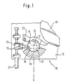
- FIG. 1 shows a sensor 10 for vehicle-sensitive triggering the locking mechanism of a (not shown) Seat belt retractor in the back of a vehicle seat shown.
- This sensor 10 comprises a base plate 12 and a ball seat 17 which has a trough 16 for receiving a sensor ball 15 and with the base plate 12 over a clear Dovetail guide seen in Fig. 2 18 is connected to the center C of the sensor ball 15 is concentric.
- the ball seat 17 is with provided an extension 19 on which an adjusting element 25 attacks. A translational adjustment of this Adjustment element 25 effects via extension 19 a pivoting of the ball receptacle 17 in the Dovetail guide 18 around the center point C the sensor ball 15.
- sensor lever 20th on On the in the recess of the ball seat 17 arranged sensor ball 15 is a sensor lever 20th on, which is mounted on a pin 22, which is also is connected to the base plate 12.
- the sensor lever 20 is provided when the sensor 10 is triggered by changing the position of the sensor ball 15 in the Ball receptacle 17 to be pivoted and with the Point at its free end into the teeth of one schematically illustrated control disc 30 of the Seat belt retractors intervene, causing this is held against rotation and a locking of the seat belt retractor triggers vehicle-sensitive.
- This is the specialist in the field of vehicle occupant safety systems well known, which is why neither on the triggering of the sensor or on the seat belt retractor will be discussed further.
- Fig. 1 the sensor 10 is shown in its constructively intended operating position, in which the direction of gravity acting on the sensor ball 15 coincides with the axis V. If the orientation of the sensor 10 changes from this position, the direction of action of the gravity acting on the sensor ball 15 assumes, for example, the directions V 1 or V 2 shown in FIG. 3. This ensures that the sensor 10 also has a triggering behavior in these positions, which corresponds to the design, the ball receptacle 17 is pivoted by the adjusting element 25 via the extension 19. This can be seen in FIG. 3, the adjusting element 25 and the ball seat 17 being shown with solid lines in the position assigned to the direction of action V 2 and with dashed lines in the position assigned to the direction of action V 1 .
- the relative position between the sensor ball 15 and the control disk 30 does not change when the ball receptacle 17 is pivoted.
- the distance between the free end of the sensor lever 20 and the circumference of the control disk 30 thus remains unchanged. Since only the ball receptacle 17 is pivoted, the installation space required for the sensor 10 is very small.
- the pivoting of the ball receptacle 17 1 in the neutral position shown in FIG. 3 shown pivoted positions is from a Causes translational movement of the adjusting element 25, which is caused by an adjusting device 27, their sensor-side end with the sensor base plate 12 is connected.
- This adjustment device 27 can Pull / push link be like a Bowden cable with which the adjusting element 25 is firmly connected.
- An adjustment the pull / push member 27 along its longitudinal direction causes a corresponding Translation movement of the adjusting element 25, the over the extension 19 to pivot the Ball receptacle 17 around the center point C of the sensor ball 15 leads.
- the adjusting device 27 can also be a rotatable one Power transmission member, its rotational movement at the sensor end of the Adjustment device 27 in a translation movement of the adjusting element 25 is implemented, e.g. by means of of a thread on the sensor-side end of the rotatable Power transmission member 27 is formed and on which the adjusting element 25, which with a complementary thread is provided, is attached.
- a rotation of the rotatable power transmission element thus acts 27 in the same way as a translational Displacement of the pull / push link.
- the end of the adjusting device 27 stands with a suitable one Device like a gear (not shown) in connection with a pivoting of the backrest of the Taps vehicle seat and such an action the adjusting element 25 ensures that the orientation of the sensor 10 regardless of the backrest inclination is maintained.
Applications Claiming Priority (2)
| Application Number | Priority Date | Filing Date | Title |
|---|---|---|---|
| DE19500722 | 1995-01-12 | ||
| DE19500722A DE19500722A1 (de) | 1995-01-12 | 1995-01-12 | Sensor für einen Sicherheitsgurtaufroller |
Publications (3)
| Publication Number | Publication Date |
|---|---|
| EP0721868A1 EP0721868A1 (de) | 1996-07-17 |
| EP0721868B1 EP0721868B1 (de) | 1999-05-06 |
| EP0721868B2 true EP0721868B2 (de) | 2002-05-02 |
Family
ID=7751343
Family Applications (1)
| Application Number | Title | Priority Date | Filing Date |
|---|---|---|---|
| EP95119927A Expired - Lifetime EP0721868B2 (de) | 1995-01-12 | 1995-12-18 | Sensor für einen Sicherheitsgurtaufroller |
Country Status (4)
| Country | Link |
|---|---|
| US (1) | US5622383A (es) |
| EP (1) | EP0721868B2 (es) |
| DE (2) | DE19500722A1 (es) |
| ES (1) | ES2093584T3 (es) |
Families Citing this family (20)
| Publication number | Priority date | Publication date | Assignee | Title |
|---|---|---|---|---|
| DE19532781C2 (de) * | 1995-09-06 | 1998-01-29 | Autoliv Dev | Sicherheitsgurtaufroller mit zwei fahrzeugsensitiven Sensoren mit unterschiedlicher Ansprechschwelle |
| US5716102A (en) * | 1996-09-26 | 1998-02-10 | Trw Vehicle Safety Systems Inc. | Emergency locking mechanism with orientation control |
| JP3465519B2 (ja) * | 1997-02-18 | 2003-11-10 | タカタ株式会社 | シートベルト装置 |
| DE19717689B4 (de) * | 1997-04-28 | 2006-09-07 | C. Rob. Hammerstein Gmbh & Co. Kg | Gurtintegralsitz eines Kraftfahrzeuges mit einem Retraktor für den Sicherheitsgurt und einem diesen steuernden Sensor |
| JP3455426B2 (ja) | 1998-06-09 | 2003-10-14 | 株式会社東海理化電機製作所 | 加速度センサ |
| GB2349119B (en) * | 1999-04-21 | 2001-05-30 | Breed Automotive Tech | A sensor for a seat belt retractor |
| DE20006314U1 (de) * | 2000-04-06 | 2000-08-17 | Trw Repa Gmbh | Trägheitssensor |
| US20060243846A1 (en) * | 2005-04-29 | 2006-11-02 | Autoliv Asp, Inc. | Vehicle sensitive seat belt retractor control with suppressed Z-axis sensitivity |
| KR100751773B1 (ko) * | 2007-01-24 | 2007-08-23 | 주식회사 삼송 | 시트벨트 리트랙터 |
| US20080217458A1 (en) * | 2007-03-05 | 2008-09-11 | Autoliv Asp, Inc. | Hybrid vehicle sensitive seat belt retractor inertial locking system |
| US7628349B2 (en) * | 2007-03-06 | 2009-12-08 | Autoliv Asp, Inc. | Inertia actuator for seat belt retractor |
| US7568649B2 (en) * | 2007-03-23 | 2009-08-04 | Autoliv Asp, Inc. | Vehicle sensitive seat belt retractor control with suppressed Z-axis sensitivity |
| DE102009052495B8 (de) | 2009-11-11 | 2012-03-22 | Autoliv Development Ab | Selbstsperrender Gurtaufroller |
| TWM409985U (en) * | 2010-10-27 | 2011-08-21 | Guo-Hao Li | Snap device for safety belt |
| DE102011103113A1 (de) * | 2011-05-25 | 2012-11-29 | Trw Automotive Gmbh | Baugruppe für einen Gurtaufroller |
| US9434347B2 (en) | 2012-12-10 | 2016-09-06 | Autoliv Asp, Inc. | Low noise, debris tolerant retractor inertial sensor |
| DE102014208570B4 (de) | 2014-05-07 | 2018-08-23 | Autoliv Development Ab | Gurtaufroller für eine Sicherheitsgurteinrichtung für ein Kraftfahrzeug |
| DE102014210396B4 (de) * | 2014-06-03 | 2021-05-27 | Autoliv Development Ab | Gurtaufroller für eine Sicherheitsgurteinrichtung für ein Kraftfahrzeug |
| DE102014111923B4 (de) * | 2014-08-20 | 2017-03-30 | Volkswagen Aktiengesellschaft | Armlehne mit Crashsicherung |
| US11794688B2 (en) * | 2021-09-14 | 2023-10-24 | Autoliv Asp, Inc. | Vehicle sensitive seat belt retractor control with suppressed Z-axis sensitivity |
Family Cites Families (12)
| Publication number | Priority date | Publication date | Assignee | Title |
|---|---|---|---|---|
| DE2402921A1 (de) * | 1974-01-22 | 1975-08-28 | Artur Foehl | Traegheitssteuerung |
| DE2513023A1 (de) * | 1975-03-25 | 1976-10-07 | Daimler Benz Ag | Durch verzoegerungskraefte ausloesbarer sensor |
| DE2658747C2 (de) * | 1976-12-24 | 1986-01-30 | Autoflug Gmbh, 2084 Rellingen | Sicherheitsgurtsystem |
| FR2377085A1 (fr) * | 1977-01-10 | 1978-08-04 | Fligue Wladimir | Relais polarise pour courants de forte intensite |
| JPS5956168A (ja) * | 1982-09-24 | 1984-03-31 | Nippon Soken Inc | 衝撃感知装置 |
| FR2565404B1 (fr) * | 1984-06-05 | 1988-03-18 | Seb Sa | Interrupteur multidirectionnel a commande par une bille |
| US4978087A (en) * | 1987-11-10 | 1990-12-18 | Britax-Kolb Gmbh & Co. | Acceleration sensor for vehicle-sensitive systems |
| JPH0256059U (es) * | 1988-10-17 | 1990-04-23 | ||
| JP2576496Y2 (ja) * | 1990-03-23 | 1998-07-09 | アイシン精機株式会社 | 加速度センサ |
| US5136127A (en) * | 1991-09-16 | 1992-08-04 | Honeywell Inc. | Tilt actuated switch |
| US5358276A (en) * | 1993-10-25 | 1994-10-25 | Trw Vehicle Safety Systems Inc. | Seat belt webbing clamp assembly |
| US5495994A (en) * | 1994-09-07 | 1996-03-05 | Trw Vehicle Safety Systems Inc. | Inertia sensitive seat belt retractor |
-
1995
- 1995-01-12 DE DE19500722A patent/DE19500722A1/de not_active Withdrawn
- 1995-12-18 EP EP95119927A patent/EP0721868B2/de not_active Expired - Lifetime
- 1995-12-18 ES ES95119927T patent/ES2093584T3/es not_active Expired - Lifetime
- 1995-12-18 DE DE59505841T patent/DE59505841D1/de not_active Expired - Fee Related
-
1996
- 1996-01-05 US US08/583,316 patent/US5622383A/en not_active Expired - Fee Related
Also Published As
| Publication number | Publication date |
|---|---|
| US5622383A (en) | 1997-04-22 |
| DE59505841D1 (de) | 1999-06-10 |
| EP0721868B1 (de) | 1999-05-06 |
| ES2093584T1 (es) | 1997-01-01 |
| EP0721868A1 (de) | 1996-07-17 |
| DE19500722A1 (de) | 1996-07-18 |
| ES2093584T3 (es) | 1999-08-16 |
Similar Documents
| Publication | Publication Date | Title |
|---|---|---|
| EP0721868B2 (de) | Sensor für einen Sicherheitsgurtaufroller | |
| DE69832680T2 (de) | Kippsensor gesteuerter Sicherheitsgurtaufroller | |
| DE10027134B4 (de) | Rückziehvorrichtung für einen Fahrzeugsicherheitsgurt | |
| EP0351551B1 (de) | Sicherheitsgurtanordnung an einem neigungsverstellbaren Kraftfahrzeugsitz | |
| DE19703625C2 (de) | Beschleunigungssensorvorrichtung für ein Fahrzeug | |
| DE2614603C2 (de) | Pendelsensor für die Sperrvorrichtung einer Sicherheitsgurteinziehvorrichtung | |
| EP3554898B1 (de) | Sicherheitsgurtaufroller | |
| EP2714475B1 (de) | Baugruppe für einen gurtaufroller | |
| EP0517864A1 (de) | Aufprallsicherung für einen fahrzeugsitz, insbesondere für einen kraftfahrzeugsitz | |
| DE2232239C2 (de) | Fahrzeugsitz | |
| DE3414316C2 (es) | ||
| DE19939340A1 (de) | Trägheitsverriegelungsbaugruppe für eine Sitzführung | |
| DE19532781C2 (de) | Sicherheitsgurtaufroller mit zwei fahrzeugsensitiven Sensoren mit unterschiedlicher Ansprechschwelle | |
| DE3109302A1 (de) | Sicherheitsverriegelung an rueckenlehnen von fahrzeugsitzen | |
| DE4218792A1 (de) | Dreipunktsicherheitsgurtsystem für Kraftfahrzeuge | |
| DE2618844A1 (de) | Sicherheitsgurtaufroller mit traegheitseinrichtung | |
| DE112008001867B4 (de) | Sitzgurtaufroller | |
| EP1083084B1 (de) | Kinderrückhaltesystem für Kraftfahrzeuge | |
| DE2529880A1 (de) | Fahrzeugempfindlicher retraktor mit einem pendel auf einem schwunghebel | |
| DE19915469B4 (de) | Armlehne für eine Fahrzeugmittelkonsole | |
| DE3611004A1 (de) | Sperreinrichtung fuer das gurtband eines einem neigungsveraenderbaren sitzteil in einem kraftwagen zugeordneten gurtrollautomaten | |
| EP0861170B1 (de) | Gurtbeschlag für einen sicherheitsgurt | |
| DE60017970T2 (de) | Sicherheitsgurt- Retraktor | |
| DE10201092A1 (de) | Sicherheitseinrichtung für Fahrzeugsitzbänke | |
| EP0377861A2 (de) | Klemmvorrichtung für einen Sicherheitsgurt eines Kraftfahrzeuges |
Legal Events
| Date | Code | Title | Description |
|---|---|---|---|
| PUAI | Public reference made under article 153(3) epc to a published international application that has entered the european phase |
Free format text: ORIGINAL CODE: 0009012 |
|
| AK | Designated contracting states |
Kind code of ref document: A1 Designated state(s): DE ES FR GB IT SE |
|
| GBC | Gb: translation of claims filed (gb section 78(7)/1977) | ||
| ITCL | It: translation for ep claims filed |
Representative=s name: DR. ING. A. RACHELI & C. |
|
| 17P | Request for examination filed |
Effective date: 19960812 |
|
| EL | Fr: translation of claims filed | ||
| REG | Reference to a national code |
Ref country code: ES Ref legal event code: BA2A Ref document number: 2093584 Country of ref document: ES Kind code of ref document: T1 |
|
| 17Q | First examination report despatched |
Effective date: 19980310 |
|
| RAP1 | Party data changed (applicant data changed or rights of an application transferred) |
Owner name: TRW OCCUPANT RESTRAINT SYSTEMS GMBH & CO. KG |
|
| GRAG | Despatch of communication of intention to grant |
Free format text: ORIGINAL CODE: EPIDOS AGRA |
|
| GRAG | Despatch of communication of intention to grant |
Free format text: ORIGINAL CODE: EPIDOS AGRA |
|
| GRAH | Despatch of communication of intention to grant a patent |
Free format text: ORIGINAL CODE: EPIDOS IGRA |
|
| GRAH | Despatch of communication of intention to grant a patent |
Free format text: ORIGINAL CODE: EPIDOS IGRA |
|
| GRAA | (expected) grant |
Free format text: ORIGINAL CODE: 0009210 |
|
| AK | Designated contracting states |
Kind code of ref document: B1 Designated state(s): DE ES FR GB IT SE |
|
| PG25 | Lapsed in a contracting state [announced via postgrant information from national office to epo] |
Ref country code: SE Free format text: THE PATENT HAS BEEN ANNULLED BY A DECISION OF A NATIONAL AUTHORITY Effective date: 19990506 Ref country code: FR Free format text: LAPSE BECAUSE OF NON-PAYMENT OF DUE FEES Effective date: 19990506 |
|
| REF | Corresponds to: |
Ref document number: 59505841 Country of ref document: DE Date of ref document: 19990610 |
|
| ET | Fr: translation filed | ||
| GBT | Gb: translation of ep patent filed (gb section 77(6)(a)/1977) |
Effective date: 19990622 |
|
| REG | Reference to a national code |
Ref country code: ES Ref legal event code: FG2A Ref document number: 2093584 Country of ref document: ES Kind code of ref document: T3 |
|
| PLAV | Examination of admissibility of opposition |
Free format text: ORIGINAL CODE: EPIDOS OPEX |
|
| PLBQ | Unpublished change to opponent data |
Free format text: ORIGINAL CODE: EPIDOS OPPO |
|
| PLBI | Opposition filed |
Free format text: ORIGINAL CODE: 0009260 |
|
| PLAV | Examination of admissibility of opposition |
Free format text: ORIGINAL CODE: EPIDOS OPEX |
|
| PLBF | Reply of patent proprietor to notice(s) of opposition |
Free format text: ORIGINAL CODE: EPIDOS OBSO |
|
| 26 | Opposition filed |
Opponent name: AUTOLIV DEVELOPMENT AB Effective date: 20000204 |
|
| PLBF | Reply of patent proprietor to notice(s) of opposition |
Free format text: ORIGINAL CODE: EPIDOS OBSO |
|
| PLBF | Reply of patent proprietor to notice(s) of opposition |
Free format text: ORIGINAL CODE: EPIDOS OBSO |
|
| PGFP | Annual fee paid to national office [announced via postgrant information from national office to epo] |
Ref country code: GB Payment date: 20001107 Year of fee payment: 6 |
|
| PGFP | Annual fee paid to national office [announced via postgrant information from national office to epo] |
Ref country code: FR Payment date: 20001204 Year of fee payment: 6 |
|
| PGFP | Annual fee paid to national office [announced via postgrant information from national office to epo] |
Ref country code: ES Payment date: 20001219 Year of fee payment: 6 |
|
| PLAW | Interlocutory decision in opposition |
Free format text: ORIGINAL CODE: EPIDOS IDOP |
|
| PLAW | Interlocutory decision in opposition |
Free format text: ORIGINAL CODE: EPIDOS IDOP |
|
| PG25 | Lapsed in a contracting state [announced via postgrant information from national office to epo] |
Ref country code: GB Free format text: LAPSE BECAUSE OF NON-PAYMENT OF DUE FEES Effective date: 20011218 |
|
| REG | Reference to a national code |
Ref country code: GB Ref legal event code: IF02 |
|
| PUAH | Patent maintained in amended form |
Free format text: ORIGINAL CODE: 0009272 |
|
| STAA | Information on the status of an ep patent application or granted ep patent |
Free format text: STATUS: PATENT MAINTAINED AS AMENDED |
|
| 27A | Patent maintained in amended form |
Effective date: 20020502 |
|
| AK | Designated contracting states |
Kind code of ref document: B2 Designated state(s): DE ES FR GB IT SE |
|
| GBPC | Gb: european patent ceased through non-payment of renewal fee |
Effective date: 20011218 |
|
| PG25 | Lapsed in a contracting state [announced via postgrant information from national office to epo] |
Ref country code: ES Free format text: LAPSE BECAUSE OF FAILURE TO SUBMIT A TRANSLATION OF THE DESCRIPTION OR TO PAY THE FEE WITHIN THE PRESCRIBED TIME-LIMIT Effective date: 20020813 |
|
| REG | Reference to a national code |
Ref country code: FR Ref legal event code: ST |
|
| EN | Fr: translation not filed | ||
| PG25 | Lapsed in a contracting state [announced via postgrant information from national office to epo] |
Ref country code: IT Free format text: LAPSE BECAUSE OF NON-PAYMENT OF DUE FEES Effective date: 20051218 |
|
| PGFP | Annual fee paid to national office [announced via postgrant information from national office to epo] |
Ref country code: DE Payment date: 20061229 Year of fee payment: 12 |
|
| PG25 | Lapsed in a contracting state [announced via postgrant information from national office to epo] |
Ref country code: DE Free format text: LAPSE BECAUSE OF NON-PAYMENT OF DUE FEES Effective date: 20080701 |