EP0721825B1 - Elektrische Haarschneidemaschine - Google Patents
Elektrische Haarschneidemaschine Download PDFInfo
- Publication number
- EP0721825B1 EP0721825B1 EP95308382A EP95308382A EP0721825B1 EP 0721825 B1 EP0721825 B1 EP 0721825B1 EP 95308382 A EP95308382 A EP 95308382A EP 95308382 A EP95308382 A EP 95308382A EP 0721825 B1 EP0721825 B1 EP 0721825B1
- Authority
- EP
- European Patent Office
- Prior art keywords
- blade
- trimmer
- immovable
- movable
- shutter plate
- Prior art date
- Legal status (The legal status is an assumption and is not a legal conclusion. Google has not performed a legal analysis and makes no representation as to the accuracy of the status listed.)
- Expired - Lifetime
Links
- 210000004209 hair Anatomy 0.000 title claims abstract description 82
- 230000000994 depressogenic effect Effects 0.000 claims description 11
- 230000007246 mechanism Effects 0.000 claims description 9
- 230000001681 protective effect Effects 0.000 abstract description 11
- 230000009979 protective mechanism Effects 0.000 abstract 1
- 238000005520 cutting process Methods 0.000 description 32
- 230000006378 damage Effects 0.000 description 8
- 239000000463 material Substances 0.000 description 4
- 229920003002 synthetic resin Polymers 0.000 description 4
- 239000000057 synthetic resin Substances 0.000 description 4
- 230000009471 action Effects 0.000 description 3
- 238000000034 method Methods 0.000 description 2
- 238000003825 pressing Methods 0.000 description 2
- 238000004873 anchoring Methods 0.000 description 1
- 238000005452 bending Methods 0.000 description 1
- 230000008859 change Effects 0.000 description 1
- 230000003111 delayed effect Effects 0.000 description 1
- 230000000881 depressing effect Effects 0.000 description 1
- 230000000694 effects Effects 0.000 description 1
- 230000009467 reduction Effects 0.000 description 1
- 230000007480 spreading Effects 0.000 description 1
- 210000002105 tongue Anatomy 0.000 description 1
- 238000009966 trimming Methods 0.000 description 1
Images


Classifications
-
- B—PERFORMING OPERATIONS; TRANSPORTING
- B26—HAND CUTTING TOOLS; CUTTING; SEVERING
- B26B—HAND-HELD CUTTING TOOLS NOT OTHERWISE PROVIDED FOR
- B26B19/00—Clippers or shavers operating with a plurality of cutting edges, e.g. hair clippers, dry shavers
- B26B19/20—Clippers or shavers operating with a plurality of cutting edges, e.g. hair clippers, dry shavers with provision for shearing hair of preselected or variable length
-
- B—PERFORMING OPERATIONS; TRANSPORTING
- B26—HAND CUTTING TOOLS; CUTTING; SEVERING
- B26B—HAND-HELD CUTTING TOOLS NOT OTHERWISE PROVIDED FOR
- B26B19/00—Clippers or shavers operating with a plurality of cutting edges, e.g. hair clippers, dry shavers
- B26B19/02—Clippers or shavers operating with a plurality of cutting edges, e.g. hair clippers, dry shavers of the reciprocating-cutter type
- B26B19/04—Cutting heads therefor; Cutters therefor; Securing equipment thereof
- B26B19/06—Cutting heads therefor; Cutters therefor; Securing equipment thereof involving co-operating cutting elements both of which have shearing teeth
-
- B—PERFORMING OPERATIONS; TRANSPORTING
- B26—HAND CUTTING TOOLS; CUTTING; SEVERING
- B26B—HAND-HELD CUTTING TOOLS NOT OTHERWISE PROVIDED FOR
- B26B19/00—Clippers or shavers operating with a plurality of cutting edges, e.g. hair clippers, dry shavers
- B26B19/38—Details of, or accessories for, hair clippers, or dry shavers, e.g. housings, casings, grips, guards
- B26B19/3806—Accessories
- B26B19/3813—Attachments
-
- B—PERFORMING OPERATIONS; TRANSPORTING
- B26—HAND CUTTING TOOLS; CUTTING; SEVERING
- B26B—HAND-HELD CUTTING TOOLS NOT OTHERWISE PROVIDED FOR
- B26B19/00—Clippers or shavers operating with a plurality of cutting edges, e.g. hair clippers, dry shavers
- B26B19/38—Details of, or accessories for, hair clippers, or dry shavers, e.g. housings, casings, grips, guards
- B26B19/3806—Accessories
- B26B19/382—Built-in accessories
Definitions
- the present invention relates to an electric hair trimmer.
- FIGs 11 and 12 show one conventional electric hair trimmer.
- Reference numeral 102 is a main body case of the trimmer 100.
- a trimmer head 104 is provided on one end of the main body case 102, and a handle (not illustrated) is provided on the other end.
- a multiple number (two in this prior art) of engaging grooves 106 which are parallel to an immovable blade and a movable blade (described later) are formed on both side surfaces of the trimmer head 104.
- the immovable blade 108 is installed in the trimmer head 104 so that the edge of the blade, which is formed into a sawtooth edge, protrudes from the upper surface of the trimmer head 104.
- the movable blade 110 is installed on the immovable blade 108 so that the movable blade 110 performs a linear reciprocating motion in the left-right direction with respect to Figure 11 while the edge of the movable blade 110, which is formed as a sawtooth edge, slides against the edge of the immovable blade 108.
- a comb attachment 112 is made of an elastically deformable material, e.g., a synthetic resin, etc., and is composed of two U-shaped members 114 positioned at a distance from each other that are connected at arm portions of the respective U-shaped members 114.
- a comb portion 116 which extends in the bending direction of the U-shaped members 114 is formed on the connected portion of the comb attachment 112.
- engaging projections 118 are formed on the inside surfaces of the tip ends of the arm portions of the U-shaped members 114.
- the comb attachment 112 is attached to the trimmer head 104 in a detachable manner.
- the comb attachment 112 is pushed over the trimmer head 104 from the direction of the end of the trimmer head on which the immovable blade 108 and movable blade 110 are installed while spreading the arm portions of the respective U-shaped members 114, thus letting the engaging project-ions 118 of the attachment 112 engage with the engaging grooves 106 of the trimmer head 104.
- the comb attachment 112 can be removed from the trimmer head 104 by shifting it in the reverse direction from that described above.
- the position of the comb attachment 112 on the trimmer head 104 can be altered, so that the amount by which the comb portion 116 extends in the direction of protrusion of the immovable blade 108 and movable blade 110 from the trimmer head 104 (i.e., upward in Figures 11 and 12) can be varied.
- the comb portion 116 brings hairs, which have acquired a certain "habit” or are lying flat, to the immovable blade 108 and movable blade 110.
- the comb portion 116 may change the height or length at which the hairs are cut.
- US-A-5,050,305 discloses a hair trimmer having an immovable blade and a movable blade which slides reciprocatingly against the immovable blade, and a demountable comb attachment which may be adjusted to any position between predetermined maximum and minimum positions of trim lengths.
- the hair that is to be cut is combed with a comb and is then cut by applying the immovable and movable blades 108 and 110 (hereafter, collectively called “the blades") of the electric hair trimmer 100 to the desired cutting position.
- the blades the immovable and movable blades 108 and 110
- the cutting position is thus adjusted, the hair may be damaged by the blades. In such cases, it would be possible to lift the blades temporarily from the hair and then reapply the blades to the hair after changing the cutting position so that the hair is not damaged. If this is done, however, the operating efficiency drops compared to cases where the trimmer is moved while being contact with the hair as described above.
- the comb portion 116 of the electric hair trimmer 100 is actually passed through the hair in order to confirm the cutting height after the attachment position of the comb attachment 112 has been altered.
- the blades are brought to contact the hair so that the comb portion 116 does not pass smoothly through the hair. Accordingly, the way to confirm the cutting height like this requires some effort; and since the hair is in contact with the blades, it is likely that the hair is easily damaged.
- the blades could be damaged when they contact hard objects since the blades stick out from the trimmer head 104 and are not covered at all. Moreover, if the blades should contact the human body, it is obviously very dangerous.
- the primary aim of embodiments of the present invention is to solve the problems with the prior art trimmers.
- the aim is to provide an electric hair trimmer which allows smooth trimming and other operations without damaging the hair during the adjustment of the cutting position and cutting height and also makes it possible to protect the blades of the trimmer.
- an electric hair trimmer that includes a main body case, a trimmer head formed at one end of the main body case, an immovable blade which is installed in the trimmer head so that the edge of the immovable blade, which is formed as a sawtooth edge, protrudes from the trimmer head, and a movable blade which is installed on the immovable blade so that the movable blade makes a linear reciprocating motion while the edge of the movable blade, which is formed as a sawtooth edge, slides against the edge of the immovable blade, and the trimmer being such that the trimmer head is provided with a shutter plate along the immovable blade and/or the movable blade so that the shutter plate can move between a first position and a second position in the direction of protrusion of the edge of the immovable blade, so that when the shutter plate is in the first position, the tip of the shutter plate protrudes beyond the edges of the immovable and movable blades, and when the shutter plate is in
- the hair trimmer of the may further include in the main body case a main switch, a driving means which causes the movable blade to make a linear reciprocating motion when the main switch is turned on, and a shutter-moving mechanism which causes the shutter plate to move into the second position only when the main switch is depressed.
- the shutter plate may automatically move into the second position when the electric hair trimmer is in operation to cut the hair; and when the operation of the electric hair trimmer is stopped, the shutter plate may automatically move into the first position and stay in the first position. Accordingly, the hair cutting operation may be stopped instantly, so that excessive cutting of the hair is prevented.
- the shutter plate being capable of moving between the first and second positions in the direction of protrusion of the edge of the immovable blade, and with the tip of the shutter plate being set to protrude beyond the edges of the immovable and movable blades when the shutter plate has moved into the first position, damage to the hair that might be caused by the blades during the adjustment of the cutting position may be prevented.
- the immovable and movable blades are both protected, and injuries to the human body by the blades may be prevented.
- the tip of the shutter plate does not protrude beyond the edges of the blades, and ordinary hair cutting can be performed.
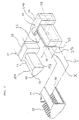
- the electric hair trimmer embodying the present invention is generally referred to by the reference numeral 10 in the Figures, and the trimmer 10 is comprised of a main body case 12 and a trimmer head 14.
- the trimmer head 14 is formed at one end of the main body case 12 (i.e., the left end in Figure 1), and a handle 16 is formed on the other end (i.e., the right end in Figure 1).
- a main switch 18 of the type operated by being depressed is provided on the front side (which is upper side in Figure 1) of the main body case 12.
- a sliding type switch could be used as the main switch 18 instead of the depression type switch.
- a head cover 20 and a comb attachment 24 on which a comb portion 22 is formed are attached to the trimmer head 14 in a detachable fashion.
- the trimmer head 14 includes an immovable blade 26.
- the immovable blade 26 is installed on a first side surface 14a (called “front surface") of the trimmer head 14 so that the edge of the blade 26, which is formed as a sawtooth edge, protrudes from the front surface (upper surface in Figure 1) of the trimmer head 14.
- the trimmer head further includes a movable blade 28.
- the movable blade 28 is installed on the front surface 14a of the trimmer head 14 so as to be along the immovable blade 26.
- the movable blade 28 can make a linear reciprocating motion in the left-right direction with respect to Figure 1 so that the edge of the movable blade 28, which is formed as a sawtooth edge, slides against the edge of the immovable blade 26.
- the edge of the movable blade 28 also protrudes from the front surface (upper surface in Figure 1) of the trimmer head 14.
- the trimmer head 14 further includes a shutter plate or protective plate 30 on the front surface 14a.
- the shutter plate 30 is in the shape of a plate made of a synthetic resin material, etc. and installed in the trimmer head 14 so as to lie along the immovable blade 26.
- the shutter plate 30 is installed so that it is positionally changeable between a first position B and a second position C in the direction of protrusion A of the edge of the immovable blade 26 as seen in Figure 1.
- the tip edge of the shutter plate 30 protrudes beyond the edges of the immovable and movable blades 26 and 28.
- the tip of the shutter plate 30 is retracted from the edges of the two blades 26 and 28, so that the sawtooth edges of both of the immovable blade 26 and movable blade 28 protrude beyond the tip edge of the shutter plate 30.
- only one shutter plate 30 is used so as to be located along the immovable blade 26.
- the shutter plate 30 can be located along the movable blade 28. It is also possible to use two shutter plates 30 so that they are located on both sides of the blades, i.e., one along the immovable blade 26 and one along the movable blade 28.
- a head cover 20 that is to be mounted on the trimmer head 14 is in a box shape which matches the external shape of the trimmer head 14.
- the head cover 20 is made of an elastically deformable material such as a synthetic resin, etc. and has a first opening (or front opening) 20a and a second opening (or bottom opening) 20b.
- the head cover 20 is attached to the hair trimmer by first aligning the front opening 20a of the head cover 20 with the second side surface (or "rear surface") 14b of the trimmer head 14, and then moving the head cover 20 toward the front surface 14a of the trimmer head 14 so that the entire trimmer head 14 is covered by the head cover 20 except for the front side surface 14a of the trimmer head 14.
- attaching of the head cover 20 on the trimmer head 14 is accomplished by letting first engaging projections 34 formed on the inside wall surfaces of the bottom opening 20b of the head cover 20 to engage with first engaging grooves 32 formed on the main body case 12 between the trimmer head 14 and the main switch 18, and then moving the head cover 20 along the first engaging grooves 32 towards the front surface 14a of the trimmer head 14 as shown by arrow X.
- the trimmer head 14 is clamped by the elastic force of the head cover 20, and the head cover 20 can be stopped at any desired position on the trimmer head 14 in the direction indicated by arrow X.
- the head cover 20 is provided with a pair of second engaging projections 36 which are used to guide a comb attachment 24 in place on the head cover 20. These second engaging projections 36 are formed on the outside wall surfaces of the front opening 20a of the head cover 20.
- the comb attachment 24 is made of an elastically deformable material such as a synthetic resin, etc., and it is in the shape of a box which is open on three sides (front, back and bottom) as best seen in Figure 2.
- a pair of engaging grooves 38 are formed on the inside wall surfaces at one of the open sides (that is, the back side) of the comb attachment 24, and a comb 22 is formed on the other side (front side) that is opposite from the rear side.
- the opened bottom side of the comb attachment 24 is between the front and back open sides and is roughly the same shape as the shape of the end configuration of the trimmer head 14.
- the comb attachment 24 is attached to the head cover 20.
- the bottom ends of the engaging grooves 38 of the comb attachment 24 are brought to engage with the top ends of the engaging projections 36 of the head cover 20, and then sliding the comb attachment 24 along the engaging projection 36 of the head cover 20 in the direction indicated by arrow Y.
- the two components, the head cover 20 and the comb attachment 24, are mounted on the trimmer head 14 in an order such that the head cover 20 is first mounted on the trimmer head 14, and then the comb attachment 24 is attached to the head cover 20 as shown in Figure 2.
- the comb attachment 24 is first removed from the head cover 20 (see Figure 3), and then the head cover 20 is removed from the trimmer head 14 (see Figure 4).
- the trimmer head 14 includes a blade case 40 which is detachable from the trimmer head 14.
- the immovable blade 26, movable blade 28 and shutter plate 30 are installed on the inside wall surfaces of this blade case 40.
- the blade case 40 is detachable from the trimmer head 14 so that hair debris which enters into the trimmer head 14 via the gaps between the immovable blade 26, movable blade 28 and shutter plate 30 during the hair cutting operation can be removed.
- the blade case 40 is attached to the trimmer head 14 by causing hooks 39 formed on both side surfaces of the blade case 40 to engage with pins 41 formed on the inside wall of the trimmer head 14.
- the structure of the blade case 40 in which the immovable blade 26, movable blade 28 and shutter plate 30 are installed will be described in detail along with the detailed structures of the blade case 40, immovable blade 26, movable blade 28 and shutter plate 30, using Figures 6 and 7.
- the blade case 40, immovable blade 26, movable blade 28, shutter plate 30 and movable lever are all formed in shapes which show left-right symmetry with respect to the center line F in Figure 6.
- Guide slots 42 are opened in the shutter plate 30, and the shutter plate 30 is mounted on the back of the blade case 40 so that columnar projections 44 formed on the back are brought into the guide slots 42.
- four guide slots are formed.
- the shutter plate 30 is attached to the blade case 40 so that the shutter plate 30 is hindered to slip out by the immovable blade 26, which is likewise fastened to the columnar projections 44 on top of the shutter plate 30.
- the shutter plate 30 attached to the blade case 40 can move up and down (in the left-right direction in Figure 7) between the first position B and the second position C along the guide slots 42 which extend in the direction of protrusion of the immovable blade 26, with movement (distance) of the shutter plate 30 being restricted in the left-right direction in Figure 6.
- leg portions 46 facing in the opposite direction from the direction of the edge of the immovable blade 26 are formed to extend from the shutter plate 30; and first driving members 48, e.g., coil springs, plate springs, etc., are installed inside the leg portions 46 between the blade case 40 and the shutter plate 30, so that the shutter plate 30 is constantly urged toward the second position C with respect to the blade case 40.
- first driving members 48 e.g., coil springs, plate springs, etc.
- the movable blade 28 is positioned on the immovable blade 26 so as to make a reciprocating motion in the left-right direction in Figure 6 while the edge of the movable blade 28 slides against the edge of the immovable blade 26.
- the movable blade 28 is integrally attached to the blade case 40 and is constantly urged toward the immovable blade 26 by second driving members 50, e.g., coil springs, plate springs, etc., which are installed in the blade case 40.
- second driving members 50 e.g., coil springs, plate springs, etc.
- a movable lever 52 is attached to the movable blade 28.
- the movable lever 52 is driven by an electric motor (not illustrated) which is a part of the driving section and is caused to perform a linear reciprocating motion via a connecting area 54 (that is another part of the driving section) which reciprocates in the front-back directions as indicated by the arrow U' in Figure 7.
- an electric motor not illustrated
- a connecting area 54 that is another part of the driving section
- the immovable blade 26, movable blade 28 and shutter plate 30 are installed in this order in the blade case 40, (b) a supporting member is installed on top of the shutter plate 30, (c) the second driving members 50 are installed between the blade case 40 and the supporting member and integrally attached to the blade case 40, and (d) the movable blade 28 reciprocates between the immovable blade 26 and the shutter plate 30.
- the structure as described in detail before in which the shutter plate 30 is between the immovable blade 26 and the blade case 40 because this structure has a greater merit in that the number of components required is less, and the structure is simple.
- the shutter-moving mechanism is provided inside the main body case 12, and it connects the main switch 18 to the shutter plate 30 and moves the shutter plate 30 into the second position C only when the main switch 18 is depressed,
- the shutter-moving mechanism is composed of the following components:
- the same shutter-moving mechanism which moves the shutter plate 30 up and down in the Figures can be realized by means of a structure which is substantially the same as the structure described above.
- the hair cutting height is set.
- the height setting is performed by changing the distance from the edge of the immovable blade 26 to the tip of the comb portion 22; in other words, it is done by moving the head cover 20 along the first engaging grooves 32 with the head cover 20 and the comb attachment 24 mounted on the trimmer head 14.
- the cutting height can be checked by actually passing the comb portion 22 through the hair without operating or depressing the main switch 18.
- the main switch 18, driving lever 60 and push-up lever 68 are in the positions shown in Figure 8; and therefore, the shutter plate 30 is pushed by the push-up lever 68 so that the shutter plate 30 is in the first position B, that is, the shutter plate 30 is at the maximum protrusion position from the trimmer head 14.
- the tip end of the shutter plate 30 projects beyond the edges of the immovable blade 26 and movable blade 28, and the hair tends not to contact the edges of the immovable blade 26 nor movable blade 28.
- the hair passes easily through the comb portion 22, and the hair cutting height can be checked smoothly. Also, damage to the hair caused by the edges of the blades can be prevented during this checking operation.
- the electric hair trimmer 10 When the hair is cut, the electric hair trimmer 10 is, with the main switch 18 "off" (i.e., not depressed), first moved by hand so that the trimmer head 14 contacts the hair while the hair is combed by the comb portion 22 or by means of a separate comb.
- the cutting position can be determined; and since the shutter plate 30 protrudes from the trimmer head 14 to a point beyond the edges of the immovable and movable blades, the hair does not come into direct contact with the blades. Therefore, even if the trimmer head 14 is moved to make fine adjustments in the cutting position, the hair will not be damaged by the blades.
- the trimmer head 14 can easily be moved obliquely and laterally with respect to the direction of the hair, so that the cutting position can be easily determined.
- the main switch 18 is depressed after the cutting position has been determined.
- the driving lever 60 pivots in the clockwise direction (indicated by arrow R) as shown in Figure 9, and the push-up lever 68 is moved obliquely downward and to the left.
- the push-up lever 68 is thus moved downward as in Figure 9
- the shutter plate 30 that is in contact with the lever 68 is also moved downward so that the shutter plate 30 is positioned in the second position C, i.e., the position of maximum intrusion into the trimmer head 14. Accordingly, the tip end of the shutter plate 30 is positioned not beyond the edges of the immovable blade 26 and movable blade 28.
- the main switch 18 When the depression of the main switch 18 is released, the main switch 18 returns to its original position (i.e., the position shown in Figure 8) by the spring 56, and the push-up lever 68 and shutter plate 30 simultaneously return to the positions shown in Figure 8 as a result of the driving force of the fourth driving members 76. Accordingly, even if the complete stop of the movable blade 28 is delayed as a result of inertial rotation of the electric motor that drives the movable blade 28 after the electric motor has been switched off, the hair cutting action of the immovable blade 26 and movable blade 28 can be immediately stopped.
- the comb attachment 24 is attached to the trimmer head 14 by first attaching the head cover 20, and then attaching the attachment to the head cover 20.
- a comb attachment 78 having the shape shown in Figure 10 and to attach such a comb attachment 78 directly to the trimmer head 14 without using a head cover 20.
- This comb attachment 78 is roughly U-shape in cross section, and the comb portion 22 is formed so as to extend from the tip of one of the arm portions of the U-shaped part.
- the comb attachment 78 can be mounted on the trimmer head 14 by fitting the comb attachment 78 over the trimmer head 14 from the side that is located on the opposite side of the trimmer head 14 from the side surface on which the immovable blade 26 is installed. With this structure, the number of components can be reduced, and a considerable reduction in cost is possible.
- engaging tongues 82 which are capable of engaging with engaging ridges 80 formed on the trimmer head 14 are formed on the other arm portion of the comb attachment 78. With this structure, the comb attachment 78 is prevented from coming off after being attached to the trimmer head 14.
- the hair trimmer embodying the present invention is described above in detail. However, the present invention is not limited to the embodiment above.
- the electric hair trimmer can be designed so that it uses no comb attachment.
- the shutter plate protects only the immovable and movable blades.
- the movement of the shutter plate is accomplished by a linkage with the mechanical action of the main switch.
- the main switch is used only as a source of electrical signal.
- an electric motor that actuates the shutter plate is employed so that the shutter plate is driven by actuating the electric motor so as to use the electrical signal as a trigger.
- a shutter plate or a protective plate is used in the trimmer head along the immovable blade and/or along the movable blade so that the shutter or protective plate is capable of moving between a first position and second position in the direction of protrusion of the edge of the immovable blade.
- the tip of the shutter plate protrudes beyond the edges of the immovable and movable blades. Accordingly, when the trimmer head is placed against the hair, almost all of the hair contacts the shutter plate, so that damage to the hair caused by the blades of the electric hair trimmer is prevented during the fine adjustment of the cutting position.
- embodiments of the present invention are applicable to an electric hair trimmer to which a comb attachment with a comb portion is attached.
- the hair is likewise prevented from contacting the edges of the blades when the hair cutting height is checked by actually passing the comb portion through the hair after the hair cutting height has been set by altering the position of the comb attachment. Accordingly, the cutting height can be checked smoothly, and damage to the hair is prevented.
- the immovable blade and the movable blade are protected by the shutter plate, injuries to the human body that might be caused by the blades can be prevented.
- the shutter or protective plate automatically moves into the second position when the main switch is depressed so that the electric hair trimmer is operated during hair cutting.
- the shutter or protective plate automatically moves into the first position.
Landscapes
- Life Sciences & Earth Sciences (AREA)
- Forests & Forestry (AREA)
- Engineering & Computer Science (AREA)
- Mechanical Engineering (AREA)
- Dry Shavers And Clippers (AREA)
- Cosmetics (AREA)
Claims (3)
- Elektrische Haarschneidemaschine (10) mit einem Schneidkopf (14), der an einem Ende eines Hauptkörpergehäuses (12) der Schneidmaschine ausgebildet ist, einer unbeweglichen Klinge (26), die an dem Schneidkopf (14) derart angebracht ist, daß eine Schneide der unbeweglichen Klinge, die als sägezahnförmige Schneide ausgebildet ist, von dem Schneidkopf (14) hervorragt und einer beweglichen Klinge (28), die an der unbeweglichen Klinge (26) derart angebracht ist, daß die bewegliche Klinge (28) eine lineare Hin- und Herbewegung durchführt, während eine Schneide der beweglichen Klinge (28), die als sägezahnförmige Schneide ausgebildet ist, sich gegenüber einer Schneide der unbeweglichen Klinge (26) verschiebt und die Schneidmaschine (10) dadurch gekennzeichnet ist, daß eine Abdeckplatte (30), die sich zwischen einer ersten Stellung und einer zweiten Stellung in einer Richtung des Vorstehens der Schneide der unbeweglichen Klinge (26) bewegen kann, in dem Schneidkopf (14), entlang der unbeweglichen (26) und beweglichen (28) Klingen angebracht ist, so daß nach Bewegung der Abdeckplatte (30) in die erste Stellung, eine Spitze bzw. eine vorderer Bereich der Abdeckplatte über die Schneiden der unbeweglichen Klinge (26) und der beweglichen Klinge (28) von dem Schneidkopf (14) hervorsteht und wenn die Abdeckplatte (30) in die zweite Stellung bewegt wurde, diese Spitze bzw. dieser vordere Bereich der Abdeckplatte (30) zurückgezogen ist von den Schneiden der unbeweglichen (26) und beweglichen (28) Klingen.
- Elektrische Haarschneidemaschine nach Anspruch 1, dadurch gekennzeichnet, daß das Hauptkörpergehäuse (12) versehen ist mit:einem Hauptschalter (18);einer Antriebseinrichtung, die hilft zu bewirken, daß die bewegliche Klinge (28) eine lineare Hin- und Herbewegung durchführt, wenn der Hauptschalter (18) gedrückt ist undeinem Abdeck-Bewegemechanismus (56,60,68,76), der die Abdeckplatte (30) dazu veranlaßt, sich nur dann in die zweite Stellung zu bewegen, wenn der Hauptschalter (18) gedrückt ist.
- Elektrische Haarschneidemaschine (10) mit:einem Hauptkörpergehäuse (12);einem Schneidkopf (14), der an einem Ende des Hauptkörpergehäuses (12) der Schneidmaschine (10) ausgebildet ist;einer unbeweglichen Klinge (26), die an dem Schneidkopf (14) derart angebracht ist, daß eine Schneide der unbeweglichen Klinge (26) von dem Schneidkopf (14) hervorsteht;einer beweglichen Klinge (28), die gleich neben der unbeweglichen Klinge (26) angebracht ist, derart, daß eine Schneide der beweglichen Klinge (28) von dem Schneidkopf (14) hervorsteht und die bewegliche Klinge (28) sich hin und her bewegt, um sich gegenüber der unbeweglichen Klinge (26) zu verschieben, dadurch gekennzeichnet, daß die Schneidmaschine (10) des weiteren umfaßt:eine Schutzplatte (30), die in dem Schneidkopf (14) vorgesehen ist, derart, daß sie gleich neben der unbeweglichen (26) oder der beweglichen (28) Klinge ist, wobei die Schutzplatte (30) sich bewegen kann zwischen einer ersten Stellung und einer zweiten Stellung, derart, daß wenn die Schutzplatte (30) sich in der ersten Stellung befindet, eine Kante der Schutzplatte (30) über die Schneiden der unbeweglichen (26) und beweglichen (28) Klingen hervorragt und wenn sich die Schutzplatte (30) in der zweiten Stellung befindet, die Kante der Schutzplatte (30) von den Schneiden der unbeweglichen (26) und beweglichen (28) Klingen zurückgezogen ist; undeinen Hauptschalter (18), der an dem Hauptkörpergehäuse (12) vorgesehen und mit einer Energiequelle verbunden ist und die bewegliche Klinge (28) zwecks Hin- und Herbewegung aktiviert, wobei der Hauptschalter (18) des weiteren verbunden ist mit der Schutzplatte (30), derart, daß die Schutzplatte aus der ersten Stellung in die zweite Stellung bewegt wird, wenn der Hauptschalter (18) angeschaltet ist, um die bewegliche Klinge (28) zu aktivieren und die Schutzplatte (30) von der zweiten Stellung in die erste Stellung bewegt wird, wenn der Hauptschalter (18) abgeschaltet ist, um die bewegliche Klinge (28) zu inaktivieren.
Applications Claiming Priority (3)
| Application Number | Priority Date | Filing Date | Title |
|---|---|---|---|
| JP244795 | 1995-01-11 | ||
| JP2447/95 | 1995-01-11 | ||
| JP00244795A JP3246845B2 (ja) | 1995-01-11 | 1995-01-11 | 電動バリカン |
Publications (3)
| Publication Number | Publication Date |
|---|---|
| EP0721825A2 EP0721825A2 (de) | 1996-07-17 |
| EP0721825A3 EP0721825A3 (de) | 1997-10-08 |
| EP0721825B1 true EP0721825B1 (de) | 2000-05-31 |
Family
ID=11529542
Family Applications (1)
| Application Number | Title | Priority Date | Filing Date |
|---|---|---|---|
| EP95308382A Expired - Lifetime EP0721825B1 (de) | 1995-01-11 | 1995-11-22 | Elektrische Haarschneidemaschine |
Country Status (7)
| Country | Link |
|---|---|
| US (1) | US5604986A (de) |
| EP (1) | EP0721825B1 (de) |
| JP (1) | JP3246845B2 (de) |
| AT (1) | ATE193478T1 (de) |
| CA (1) | CA2164393C (de) |
| DE (1) | DE69517297T2 (de) |
| MX (1) | MX9600173A (de) |
Families Citing this family (4)
| Publication number | Priority date | Publication date | Assignee | Title |
|---|---|---|---|---|
| RU2700884C2 (ru) * | 2015-02-04 | 2019-09-23 | Конинклейке Филипс Н.В. | Режущая головка и устройство для стрижки волос |
| EP3911481B1 (de) * | 2019-01-15 | 2023-03-22 | Carefusion 2200, Inc. | Angetriebene haarschneidemaschine mit klingenanordnungen mit klingenaufhängungsanordnungen |
| CN111558956B (zh) * | 2020-06-15 | 2025-01-14 | 慈溪市吉望刀剪有限公司 | 一种推剪刀头及其毛发推剪器 |
| EP4063088A1 (de) * | 2021-03-26 | 2022-09-28 | Koninklijke Philips N.V. | Haardetektion in einem haarschneidesystem |
Family Cites Families (5)
| Publication number | Priority date | Publication date | Assignee | Title |
|---|---|---|---|---|
| DE3218208A1 (de) * | 1982-05-14 | 1983-11-24 | Braun Ag, 6000 Frankfurt | Haarschneidmaschine |
| US5050305A (en) * | 1985-09-13 | 1991-09-24 | Remington Products, Inc. | Hair trimmer with comb attachment |
| JPS62114588A (ja) * | 1985-11-14 | 1987-05-26 | 松下電工株式会社 | バリカン |
| NL8800132A (nl) * | 1988-01-21 | 1989-08-16 | Philips Nv | Haarknipapparaat. |
| US5084974A (en) * | 1991-01-22 | 1992-02-04 | Andis Company | Clipper with lever actuated adjustable comb |
-
1995
- 1995-01-11 JP JP00244795A patent/JP3246845B2/ja not_active Expired - Fee Related
- 1995-06-06 US US08/466,407 patent/US5604986A/en not_active Expired - Fee Related
- 1995-11-22 AT AT95308382T patent/ATE193478T1/de active
- 1995-11-22 EP EP95308382A patent/EP0721825B1/de not_active Expired - Lifetime
- 1995-11-22 DE DE69517297T patent/DE69517297T2/de not_active Expired - Fee Related
- 1995-12-04 CA CA002164393A patent/CA2164393C/en not_active Expired - Fee Related
-
1996
- 1996-01-09 MX MX9600173A patent/MX9600173A/es unknown
Also Published As
| Publication number | Publication date |
|---|---|
| DE69517297D1 (de) | 2000-07-06 |
| EP0721825A2 (de) | 1996-07-17 |
| MX9600173A (es) | 1997-01-31 |
| EP0721825A3 (de) | 1997-10-08 |
| JP3246845B2 (ja) | 2002-01-15 |
| JPH08187375A (ja) | 1996-07-23 |
| CA2164393C (en) | 1999-08-31 |
| US5604986A (en) | 1997-02-25 |
| DE69517297T2 (de) | 2000-10-05 |
| ATE193478T1 (de) | 2000-06-15 |
| CA2164393A1 (en) | 1996-07-12 |
Similar Documents
| Publication | Publication Date | Title |
|---|---|---|
| US5699616A (en) | Electric hair trimmer | |
| EP2140987B1 (de) | Klingenanordnung | |
| US5054199A (en) | Hair cutter | |
| US7761998B2 (en) | Wet razor and electric trimmer assembly | |
| CN1102088C (zh) | 干式剃须装置 | |
| EP0447131B1 (de) | Klingeneinheit für elektrischen Haarschneider | |
| JPH04117986A (ja) | 電気バリカン | |
| US20100018057A1 (en) | Electric shaver | |
| CN1215360A (zh) | 包括具有调节钮和开/关钮的剪发装置的剪发系统 | |
| US6610946B2 (en) | Actuation mechanism for a power tool | |
| JP3367562B2 (ja) | 電気的毛刈込機 | |
| US5386631A (en) | Shaving apparatus with a movable trimmer | |
| US6226869B1 (en) | Electric shaver | |
| EP0721825B1 (de) | Elektrische Haarschneidemaschine | |
| US5964034A (en) | Electric shaver having floating trimmer blades, a main blade, and hair raising portions | |
| EP3774211B1 (de) | Haarschneidevorrichtung | |
| US3531862A (en) | Taper adjustment mechanism for clipper | |
| US20020178586A1 (en) | Razor | |
| JP3363151B2 (ja) | 電気ひげそり装置 | |
| US4074427A (en) | Auxiliary trimmer assembly | |
| US3711944A (en) | Electric dry shaver | |
| JPH105457A (ja) | ヘアーカッター | |
| JPS62148687A (ja) | バリカン | |
| WO2006051620A1 (ja) | 電気バリカン用ヘッド組立体 | |
| JPH1015258A (ja) | 電気かみそり |
Legal Events
| Date | Code | Title | Description |
|---|---|---|---|
| PUAI | Public reference made under article 153(3) epc to a published international application that has entered the european phase |
Free format text: ORIGINAL CODE: 0009012 |
|
| AK | Designated contracting states |
Kind code of ref document: A2 Designated state(s): AT BE CH DE DK ES FR GB GR IE IT LI LU MC NL PT SE |
|
| PUAL | Search report despatched |
Free format text: ORIGINAL CODE: 0009013 |
|
| AK | Designated contracting states |
Kind code of ref document: A3 Designated state(s): AT BE CH DE DK ES FR GB GR IE IT LI LU MC NL PT SE |
|
| 17P | Request for examination filed |
Effective date: 19971206 |
|
| 17Q | First examination report despatched |
Effective date: 19990323 |
|
| GRAG | Despatch of communication of intention to grant |
Free format text: ORIGINAL CODE: EPIDOS AGRA |
|
| GRAG | Despatch of communication of intention to grant |
Free format text: ORIGINAL CODE: EPIDOS AGRA |
|
| GRAH | Despatch of communication of intention to grant a patent |
Free format text: ORIGINAL CODE: EPIDOS IGRA |
|
| GRAH | Despatch of communication of intention to grant a patent |
Free format text: ORIGINAL CODE: EPIDOS IGRA |
|
| GRAA | (expected) grant |
Free format text: ORIGINAL CODE: 0009210 |
|
| ITF | It: translation for a ep patent filed | ||
| AK | Designated contracting states |
Kind code of ref document: B1 Designated state(s): AT BE CH DE DK ES FR GB GR IE IT LI LU MC NL PT SE |
|
| PG25 | Lapsed in a contracting state [announced via postgrant information from national office to epo] |
Ref country code: NL Free format text: LAPSE BECAUSE OF FAILURE TO SUBMIT A TRANSLATION OF THE DESCRIPTION OR TO PAY THE FEE WITHIN THE PRESCRIBED TIME-LIMIT Effective date: 20000531 Ref country code: LI Free format text: LAPSE BECAUSE OF FAILURE TO SUBMIT A TRANSLATION OF THE DESCRIPTION OR TO PAY THE FEE WITHIN THE PRESCRIBED TIME-LIMIT Effective date: 20000531 Ref country code: GR Free format text: LAPSE BECAUSE OF NON-PAYMENT OF DUE FEES Effective date: 20000531 Ref country code: ES Free format text: THE PATENT HAS BEEN ANNULLED BY A DECISION OF A NATIONAL AUTHORITY Effective date: 20000531 Ref country code: CH Free format text: LAPSE BECAUSE OF FAILURE TO SUBMIT A TRANSLATION OF THE DESCRIPTION OR TO PAY THE FEE WITHIN THE PRESCRIBED TIME-LIMIT Effective date: 20000531 Ref country code: BE Free format text: LAPSE BECAUSE OF FAILURE TO SUBMIT A TRANSLATION OF THE DESCRIPTION OR TO PAY THE FEE WITHIN THE PRESCRIBED TIME-LIMIT Effective date: 20000531 Ref country code: AT Free format text: LAPSE BECAUSE OF FAILURE TO SUBMIT A TRANSLATION OF THE DESCRIPTION OR TO PAY THE FEE WITHIN THE PRESCRIBED TIME-LIMIT Effective date: 20000531 |
|
| REF | Corresponds to: |
Ref document number: 193478 Country of ref document: AT Date of ref document: 20000615 Kind code of ref document: T |
|
| REG | Reference to a national code |
Ref country code: CH Ref legal event code: EP |
|
| REF | Corresponds to: |
Ref document number: 69517297 Country of ref document: DE Date of ref document: 20000706 |
|
| REG | Reference to a national code |
Ref country code: IE Ref legal event code: FG4D |
|
| PG25 | Lapsed in a contracting state [announced via postgrant information from national office to epo] |
Ref country code: SE Free format text: LAPSE BECAUSE OF FAILURE TO SUBMIT A TRANSLATION OF THE DESCRIPTION OR TO PAY THE FEE WITHIN THE PRESCRIBED TIME-LIMIT Effective date: 20000831 Ref country code: PT Free format text: LAPSE BECAUSE OF FAILURE TO SUBMIT A TRANSLATION OF THE DESCRIPTION OR TO PAY THE FEE WITHIN THE PRESCRIBED TIME-LIMIT Effective date: 20000831 Ref country code: DK Free format text: LAPSE BECAUSE OF FAILURE TO SUBMIT A TRANSLATION OF THE DESCRIPTION OR TO PAY THE FEE WITHIN THE PRESCRIBED TIME-LIMIT Effective date: 20000831 |
|
| ET | Fr: translation filed | ||
| NLV1 | Nl: lapsed or annulled due to failure to fulfill the requirements of art. 29p and 29m of the patents act | ||
| PG25 | Lapsed in a contracting state [announced via postgrant information from national office to epo] |
Ref country code: LU Free format text: LAPSE BECAUSE OF NON-PAYMENT OF DUE FEES Effective date: 20001122 Ref country code: IE Free format text: LAPSE BECAUSE OF NON-PAYMENT OF DUE FEES Effective date: 20001122 |
|
| PG25 | Lapsed in a contracting state [announced via postgrant information from national office to epo] |
Ref country code: MC Free format text: THE PATENT HAS BEEN ANNULLED BY A DECISION OF A NATIONAL AUTHORITY Effective date: 20001130 |
|
| REG | Reference to a national code |
Ref country code: CH Ref legal event code: PL |
|
| PLBE | No opposition filed within time limit |
Free format text: ORIGINAL CODE: 0009261 |
|
| STAA | Information on the status of an ep patent application or granted ep patent |
Free format text: STATUS: NO OPPOSITION FILED WITHIN TIME LIMIT |
|
| 26N | No opposition filed | ||
| REG | Reference to a national code |
Ref country code: IE Ref legal event code: MM4A |
|
| REG | Reference to a national code |
Ref country code: GB Ref legal event code: IF02 |
|
| PGFP | Annual fee paid to national office [announced via postgrant information from national office to epo] |
Ref country code: GB Payment date: 20041109 Year of fee payment: 10 |
|
| PGFP | Annual fee paid to national office [announced via postgrant information from national office to epo] |
Ref country code: DE Payment date: 20041126 Year of fee payment: 10 |
|
| PGFP | Annual fee paid to national office [announced via postgrant information from national office to epo] |
Ref country code: FR Payment date: 20041130 Year of fee payment: 10 |
|
| PG25 | Lapsed in a contracting state [announced via postgrant information from national office to epo] |
Ref country code: IT Free format text: LAPSE BECAUSE OF NON-PAYMENT OF DUE FEES;WARNING: LAPSES OF ITALIAN PATENTS WITH EFFECTIVE DATE BEFORE 2007 MAY HAVE OCCURRED AT ANY TIME BEFORE 2007. THE CORRECT EFFECTIVE DATE MAY BE DIFFERENT FROM THE ONE RECORDED. Effective date: 20051122 Ref country code: GB Free format text: LAPSE BECAUSE OF NON-PAYMENT OF DUE FEES Effective date: 20051122 |
|
| PG25 | Lapsed in a contracting state [announced via postgrant information from national office to epo] |
Ref country code: DE Free format text: LAPSE BECAUSE OF NON-PAYMENT OF DUE FEES Effective date: 20060601 |
|
| GBPC | Gb: european patent ceased through non-payment of renewal fee |
Effective date: 20051122 |
|
| PG25 | Lapsed in a contracting state [announced via postgrant information from national office to epo] |
Ref country code: FR Free format text: LAPSE BECAUSE OF NON-PAYMENT OF DUE FEES Effective date: 20060731 |
|
| REG | Reference to a national code |
Ref country code: FR Ref legal event code: ST Effective date: 20060731 |