EP0447131B1 - Klingeneinheit für elektrischen Haarschneider - Google Patents
Klingeneinheit für elektrischen Haarschneider Download PDFInfo
- Publication number
- EP0447131B1 EP0447131B1 EP91301924A EP91301924A EP0447131B1 EP 0447131 B1 EP0447131 B1 EP 0447131B1 EP 91301924 A EP91301924 A EP 91301924A EP 91301924 A EP91301924 A EP 91301924A EP 0447131 B1 EP0447131 B1 EP 0447131B1
- Authority
- EP
- European Patent Office
- Prior art keywords
- blade
- guide
- reciprocating
- assembly
- edge
- Prior art date
- Legal status (The legal status is an assumption and is not a legal conclusion. Google has not performed a legal analysis and makes no representation as to the accuracy of the status listed.)
- Expired - Lifetime
Links
- 208000019300 CLIPPERS Diseases 0.000 title claims description 27
- 208000021930 chronic lymphocytic inflammation with pontine perivascular enhancement responsive to steroids Diseases 0.000 title claims description 27
- 238000007373 indentation Methods 0.000 claims description 34
- 238000005520 cutting process Methods 0.000 claims description 10
- 230000000295 complement effect Effects 0.000 claims description 4
- 238000003825 pressing Methods 0.000 claims description 3
- 230000000712 assembly Effects 0.000 description 4
- 238000000429 assembly Methods 0.000 description 4
- 238000004140 cleaning Methods 0.000 description 3
- 230000013011 mating Effects 0.000 description 3
- 230000000994 depressogenic effect Effects 0.000 description 2
- 239000007787 solid Substances 0.000 description 2
- 230000000694 effects Effects 0.000 description 1
- 238000004519 manufacturing process Methods 0.000 description 1
- 239000002184 metal Substances 0.000 description 1
- 238000000034 method Methods 0.000 description 1
- 238000009877 rendering Methods 0.000 description 1
- 238000004904 shortening Methods 0.000 description 1
Images


Classifications
-
- B—PERFORMING OPERATIONS; TRANSPORTING
- B26—HAND CUTTING TOOLS; CUTTING; SEVERING
- B26B—HAND-HELD CUTTING TOOLS NOT OTHERWISE PROVIDED FOR
- B26B19/00—Clippers or shavers operating with a plurality of cutting edges, e.g. hair clippers, dry shavers
- B26B19/02—Clippers or shavers operating with a plurality of cutting edges, e.g. hair clippers, dry shavers of the reciprocating-cutter type
- B26B19/04—Cutting heads therefor; Cutters therefor; Securing equipment thereof
- B26B19/06—Cutting heads therefor; Cutters therefor; Securing equipment thereof involving co-operating cutting elements both of which have shearing teeth
Definitions
- This invention relates to electric hair clippers and blade assemblies for electric hair clippers, and more particularly to electric hair clippers with blade assemblies which can be easily installed without screws or the like, and do not inadvertently become inoperable during normal servicing.
- Electric hair clippers and trimmers have a stationary blade and a reciprocating blade.
- the reciprocating blade In clippers containing a rotary electric motor the reciprocating blade is moved laterally back and forth over the stationary blade as a motor shaft turns a cam eccentric which is operatively connected to the reciprocating blade.
- the reciprocating blade and several associated pieces are assembled in the handle, and the stationary blade is placed over the reciprocating blade and secured to the handle by screws or the like. Installing or changing the blade assembly for servicing requires use of a special tool, such as a screw driver.
- Some hair clippers have detachable blade assemblies which can be installed and removed without hand tools by securing the assembly to the handle of the clipper with snaps.
- the reciprocating blades in such assemblies can be held in place by wire tension springs which reciprocate with the blade, thereby creating minimal frictional loads on the motor.
- wire tension springs often do not provide accurate and rigid lateral guiding with respect to the stationary blade.
- the reciprocating blade can rotate to a degree, particularly under substantial cutting loads.
- This rotation can cause the points of the teeth of the reciprocating blade to move beyond the stationary blade and nick the skin.
- Rotation of the blade can be prevented by securing the reciprocating blade with a heavier stationary metal tension spring as seen in U.S. Patent No. 2,928,171 by J. Oster.
- a heavier stationary metal tension spring as seen in U.S. Patent No. 2,928,171 by J. Oster.
- this method of correction results in increased frictional resistance being placed on the motor, which is undesirable.
- an electric hair clipper comprising a handle (in the form of a housing) and a blade assembly (that is a trimmer), this blade assembly having a base having means for securing this assembly to the clipper handle (the trimmer being pivotably mounted in a head frame); a stationary blade (in the form of one clipping element) secured to the base, this stationary blade having a plurality of stationary teeth arranged in a row and having tips which form a substantially straight blade edge; a reciprocating blade (in the form of the other clipping element) having a plurality of teeth which complement the stationary blade teeth and which have tips which form a substantially straight line substantially parallel to and adjacent the blade edge, the reciprocating blade being slidable over a maximum distance; spring means (formed by an elastic clamping member) for slidably pressing the reciprocating blade against the stationary blade for reciprocating of the reciprocating blade; means for moving the reciprocating blade within said maximum distance so that the reciprocating blade travels over a predetermined operating stroke distance; first means (formed
- an assembly constituting an electric hair clipper comprising: a handle and a blade assembly, said blade assembly having: a base having means for securing said assembly to said clipper handle, a stationary blade secured to said base, said stationary blade having a plurality of stationary teeth arranged in a row, said stationary teeth having tips which form a substantially straight blade edge, a reciprocating blade having a plurality of teeth which complement said stationary blade teeth, said reciprocating teeth having tips which form a substantially straight line substantially parallel to and adjacent said blade edge, said reciprocating blade being slidable over a maximum distance, spring means for slidably pressing said reciprocating blade against said stationary blade for reciprocation of said reciprocating blade, means for moving said reciprocating blade within said maximum distance so that said reciprocating blade travels over a predetermined operating stroke distance, first means for maintaining said line parallel to said blade edge throughout said operating stroke distance, even under substantial cutting loads, but not throughout said maximum distance, and separate second means for maintaining said blade edge parallel to said line when said reciprocating blade edge is manually moved in excess
- rotation of the reciprocating blade has been reduced or eliminated by placing fixed blade guides adjacent each side of the stationary blade and installing a guide piece on the reciprocating blade.
- the cam eccentric rotates and moves the reciprocating blade and the guide piece through an operating stroke determined by the lateral distance the cam eccentric moves as it rotates.
- the guide piece is confined within the blade guides throughout the operating stroke so that the reciprocating blade can only move laterally.
- the reciprocating blade cannot rotate and is maintained parallel to the stationary blade, without substantially increasing the frictional resistance load on the motor.
- the reciprocating blade When this type of blade assembly is detached from the clipper handle, such as for servicing, the reciprocating blade may be moved back and forth manually, to remove accumulated hair cuttings from the assembly.
- the reciprocating blade may also be moved in this manner if it is dropped when the assembly is detached from the handle.
- the reciprocating blade When moved manually, the reciprocating blade can travel through a distance which is longer than the operating stroke. Due to certain manufacturing and design constraints, explained below, it is possible for the guide piece to become disengaged from the blade guides when pushed far enough beyond one of the distal ends of the operating stroke. At this point the blade can rotate slightly, causing the guide piece to become locked against the edge of the blade guides. If the blade assembly is placed back on the handle in this condition, it will not operate.
- the internal working of the blade assembly is hidden by the solid side walls of the hair clipper case.
- Hair clippers are usually designed so that the case has dimensions which are as small as practical, but large enough to permit the reciprocating blade to move through its operating stroke without contacting the solid walls of the case.
- the preferred case width has placed design constraints on the relative sizes of the guide piece, the blade guide and the stroke distance the reciprocating blade can travel within the handle. Due to these constraints, when the blade assembly is removed from the handle it is possible for the guide piece to be displaced from the blade guide when the guide piece is pushed beyond a distal end of the operating stroke of the reciprocating blade. The guide piece is then locked against the inside edge of the blade guide. In that event, the reciprocating blade cannot move back and forth, and when replaced on the handle, the clipper does not operate.
- the present invention provides a blade assembly for an electric hair clipper having a reciprocating blade fixed by a wire tension spring, which does not rotate under substantial cutting loads and can not be accidentally displaced out of its guide path and locked in an unmovable position when the blade assembly is removed from the handle and the reciprocating blade is pushed beyond a distal end of the operating stroke.
- the present invention thus provides an electric hair clipper or trimmer having a blade assembly which is easy to assemble and install, without the use of special tools, and in which there is accurate lateral guiding of the blade assembly while placing minimal frictional loads on the motor and without the reciprocating blade being accidentally displaced out of the blade guide when detached from the clipper and pushed beyond a distal end of the operating stroke.
- the base can be snapped to the handle for operation, or removed for cleaning or other servicing, without removing screws or using hand tools.
- the or each guide bar prevents rotation of the reciprocating blade, thereby maintaining the reciprocating blade parallel to the stationary blade throughout the operating stroke, even under heavy cutting loads.
- the guide bar(s) cannot maintain the reciprocating blade parallel to the stationary blade once the reciprocating blade travels beyond a distal end of the operating stroke.
- one end of the or each guide bar becomes disengaged from the blade guide, and it becomes possible for the reciprocating blade to rotate slightly, causing the disengaged end of the or each guide bar to become locked against the inside edge of the blade guide.
- the or each additional anti-lock rib (located on the fixed blade guide(s) and engaging the guide bar(s) to maintain the reciprocating blade parallel to the stationary blade when the reciprocating blade travels beyond a distal end of the operating stroke and throughout the entire maximum stroke) serves to keep the reciprocating blade from being displaced out of the blade guide and locked against an inside edge of the blade guide if the reciprocating blade is moved beyond a distal end of its operating stroke when the blade assembly is removed from the handle for servicing.
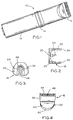
- hair clipper apparatus 10 includes a handle 12 having a switch 14 and a blade assembly 16.
- the handle 12 has a front end 18 with a wall 20 and a cavity 22 (FIG. 2).
- the blade assembly 16 covers the cavity 22 when secured to the handle 12 (FIG. 1).
- the front end 18 includes a plurality of resilient protrusions 24 and a first orifice 26 (FIG. 3) for securement of the blade assembly 16.
- the blade assembly 16 can also be secured in any other suitable manner, such as with screws or the like.
- a cam eccentric 28 is secured to a shaft 30 as seen in FIG. 2.
- the cam eccentric 28 is offset from the axis of the shaft 30.
- the cam eccentric 28 is moved in a circular motion as a motor (not shown), powered by suitable power means, causes the shaft 30 to rotate.
- the lateral distance the cam eccentric 28 moves determines the operating stroke distance A of the moving blade in the blade assembly 16, shown in FIG. 5.
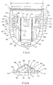
- the blade assembly 16 (FIGS. 5 and 6) includes a base 32, a stationary blade 34, a reciprocating blade 36, and a wire tension spring 38. Mating protrusions 40 are provided which interlock with the resilient protrusions 24 on the front end 18 (FIGS. 2 and 3). An additional protrusion 42 is provided on the base 32 which interlocks with the handle 12 in the first orifice 26. In this manner, the blade assembly 16 is secured to the handle 12 by snapping the pieces together, without the use of tools. The blade assembly 16 can also be removed without the use of tools, by simply pulling the blade assembly 16 away from the handle 12.
- the base 32 includes a generally flat inside surface 44 and a straight first edge 46, as well as the mating protrusions 40 (FIGS. 5 and 11).
- Two spaced reciprocating blade guides 48 are located adjacent to the first edge 46. The blade guides 48 extend to approximately the inner surface of the cavity 22 of the handle 12 when installed.
- the base 32 also includes two spaced stationary blade mounting posts 58 (FIGS. 11 and 12).
- the mounting posts 58 are perpendicular to the surface 44, and are used to secure the stationary blade 34 to the base 32, as will be seen.
- each blade guide 48 includes a rear portion 50 and a front portion 52, which define first indentations 54 (FIGS. 6, 11 and 12).
- the rear portion 50 is wider than the front portion 52 (FIGS. 5 and 11).
- the first indentations 54 include anti-locking ribs 56 which are oriented parallel to the straight first edge 56 (FIGS. 6, 11 and 12).
- a second indentation 60 is provided in the base 32.
- the second indentation 60 is generally between the blade guides 48 and behind the mounting posts 58. When the blades 48, 50 are secured in the blade assembly 16, the second indentation 60 extends beyond the ends of the blades, as seen in FIG. 5.
- the outside of the base 32 includes several surfaces 62, 64 and 66 which are provided so that the appearance of the base 32 fits well with the handle 12, in an aesthetically pleasing manner.
- the stationary blade 34 includes a plurality of first teeth 68 which are arranged in a substantially straight row.
- the first teeth 68 have first tips 70 which form a substantially straight blade edge 72.
- the blade 34 also includes first and second flat surfaces 74 and 76 which are parallel to the blade edge 72, a depressed area 78 between the surfaces 74 and 76, and two second orifices 80 in the depressed area 78.
- the mounting posts 58 fit through the second orifices 80 and are secured in a suitable manner to properly align and secure the blade 48 to the base 32.
- the reciprocating blade 36 is shown in greater detail in FIGS. 13, 23 and 24.
- the blade 36 includes a plurality of second teeth 82 (FIG. 13) which complement the stationary blade first teeth 68, a third flat surface 84 which complements the first flat surface 74, a fourth flat surface 86 which complements the second surface 76, and a raised portion 88 between the third and fourth surfaces 84 and 86.
- Second tips 90 of the second teeth 82 form a substantially straight line 92.
- the line 90 is substantially parallel to the blade edge 72 (FIG. 6) so that the teeth of the blades pass across each other properly as the reciprocating blade 36 moves back and forth during operation.
- the line 92 is preferably recessed somewhat from the blade edge 72 (FIG. 6), so that the moving second blade teeth 82 do not graze the skin during use.
- a guide piece 94 is secured to the reciprocating blade 36 (FIGS. 13, 23 and 24).
- the guide piece 94 includes two guide bars 96 which fit into the rectangular first indentations 54 and engage the anti-locking ribs 56 (FIG. 6).
- the guide bars 96 extend from the sides of the guide piece 94, parallel to the straight line 92 (FIG. 5 and 13).
- the guide bars 96 control the movement of the reciprocating blade 36 so that the line 92 is maintained in a parallel relationship to the blade edge 72, throughout the operating stroke A, even under substantial cutting loads.
- the reciprocating blade 36 can be moved manually through a maximum stroke distance B (FIG. 5).
- the guide bars 96 do not maintain the line 92 parallel to the blade edge 72 when the blade assembly 16 is removed from the handle 12 and the reciprocating blade 36 is moved sufficiently far enough beyond a distal end of the operating strocke A, so that one end of the guide bar becomes disengaged from the blade guide.
- the reciprocating blade 36 and the guide piece 94 include an elongated opening 98 (FIGS. 5 and 13) which is large enough for the cam eccentric 28.
- the guide piece 94 has two raised stops 100 which are on either side of the opening 98 so that the cam eccentric 28 alternately pushes the two stops 100 to move the blade 36 in a reciprocating motion.
- the stops 100 are elongated so that the cam eccentric 28 presses against one of the stops 100 throughout the entire range of its lateral movement.
- the reciprocating blade is moved in a side to side motion through the stroke distance A (FIG. 5).
- the guide piece 94 also has two third indentations 102 (FIG. 13) which secure the ends of the wire tension spring 38, as will be seen.
- the wire tension spring 38 shown in detail in FIGS. 9 and 10, includes two second ends 104 which fit into the third indentations 102, two bent pieces 106 and a U-shaped underside 108 which joins the bent pieces 106.
- the underside 108 is placed beneath the stationary blade 34 in the second indentation 60, and the ends 104 are located in the third indentations 102 of the guide piece 94 (FIG. 5).
- the spring 38 places tension spring pressure on the reciprocating blade 36 which holds the blade 36 against the stationary blade 34 without preventing the blade 36 from reciprocating.
- the second ends 104 move back and forth with the reciprocating blade 36.
- the guide bars 96 are "H" shaped with a front upright 110 and a rear upright 112 (FIG. 23).
- the anti-locking ribs 56 engage both the left and right uprights 112 (FIGS. 5 and 6).
- the guide bars 96 have a modified "H" shape (FIG. 24) with a front upright 110, a rear upright 112 and a middle projection 114. This shape allows a closer engagement of the guide bars 96 with the anti-locking ribs 56.
- the invention can perhaps be better understood with reference to a preferred embodiment, as seen in FIG. 5.
- the number of teeth in the blades, and the size of and spacing between the teeth, are determined by design constraints and the application for the hair clipper.
- the operating stroke A is related to the size and spacing of the blade teeth.
- the blade 36 can be manually moved over a maximum stroke distance B which is greater than the operating stroke A.
- the blade 36 can be moved to the left in FIG. 5 until the first left edge 116 of the guide bars 96 reaches a left distal end 118.
- the first right edge 120 of the guide bars 96 is at a right point 122 on the right side of the base 32.
- the left distal end 118 is reached when the blade 36 first contacts the left blade guide 48. This could happen, for example, if the second left edge 124 of the blade 36 first contacts the third right edge 126 of the front portion 52 of the left blade guide 48.
- the blade 36 can be moved to the right in FIG. 5 until the first right edge 120 of the guide bars 96 reaches a right distal end 128.
- the first right edge 120 is at the right distal and 128, the first left edge 116 of the guide bars 96 is at a left point 130 on the left side of the base 32.
- the right distal end 128 is reached when the blade 36 first contacts the right blade guide 48. This could happen, for example, if the second right edge 132 of the blade 36 first contacts the third left edge 134 of the front portion 52 of the right blade guide 48.
- the left point 130 is inside the third right edge 126, and the right point 122 is inside the third left edge 134.
- the third edges 126 and 134 cannot be extended inwardly without reducing the operating stroke, which is undesirable.
- the second edges 124 and 132 cannot be moved closer together since this could cause the reciprocating blade 36 to have less than the desired rigidity.
- the left guide bars 96 could be pushed up when at the distal point 130, as indicated in FIG. 5 by the arrow C, and the first left edge 116 could lock against the third right edge 126, rendering the reciprocating blade 36 inoperable. This could also happen if the right guide bars 96 were pushed up when at the distal point 122, as indicated in FIG. 5 by the arrow D, and the first right edge 120 could lock against the third left edge 134.
- the present invention solves this problem without shortening the operating stroke and without placing additional frictional load on the motor, by placing the anti-locking ribs 56 adjacent one upright 112 (FIG. 6), or 110 (FIG. 15) of the guide bars 96, in the manner shown in FIG. 6. In this manner, the blade line 92 of the reciprocating blade 36 is maintained parallel to the blade edge 72 throughout the maximum distance B through which the blade 36 can travel.
- the structure by which this invention is implemented depends in part on the structure of the blade assembly 16, specifically, the blade guides 48 and guide piece 94.
- the rear portions 50 of the blade guides 48 are wider than the front portions 52 (FIG. 11), and the front section 136 of the guide piece 94 is wider than the rear section 138 (FIG. 13).
- the guide bars 96 have an "H" shape, as seen in FIGS. 6 and 23.
- the anti-locking ribs 56 are located to the rear of the first indentations 54 (FIGS. 11 and 12), and engage the rear uprights 112 (FIG. 6).
- the guide bars 96 could have the modified "H" shape, shown in FIG. 24, allowing the anti-locking ribs to engage both the rear upright 112 and the middle projection 114.
- the front portions 140 of the blade guides 48 are wider than the rear portions 142 (FIG. 14), and the rear section 144 of the guide piece 94 is wider than the front section 146 (FIG. 16).
- the guide bars 96 have an "H" shape, and the anti-locking ribs 56 are located to the front of the first indentations 54 (FIG. 14 and 15), engaging the front uprights 110.
- the guide bars 96 could have the modified "H" shape shown in FIG. 24, allowing the anti-locking ribs to engage both the front upright 110 and the middle projection 114.
- the relative widths of the front portions 148 and the rear portions 150 are generally equal (FIG. 17).
- the front section 152 of the guide piece 94 is the same width as the rear section 154 (FIG. 19), and the guide bars 96 have an "H" shape.
- the anti-locking ribs 56 are located both to the front and to the back of the first indentations 54, (FIGS. 17 and 18) engaging both uprights 112 and 110 (not shown).
- the anti-locking ribs 56 could be made so that a single anti-locking guide rib 56 engages both uprights 112 and 110 (not shown).
- the guide bars 96 could have a modified "H" shape (FIG. 24), and the anti-locking ribs could be located either to the front or the rear of the first indentations 54, engaging the middle projection 114 and either the front upright 110 or the rear upright 112.
- an anti-lock bar 156 (FIG. 20) is secured within the first indentations 54 (FIGS. 21 and 22).
- the anti-lock bar 156 includes spaced upright projections 158 (FIG. 20) extending parallel to the blade edge 72 which engage the uprights 112 and 110. Legs 160, 162 extend over the blade guide 48, as shown in FIG. 22.
- the anti-locking bar 156 may be used in conjunction with any previous embodiments in place of the anti-lock ribs 56.
- the blade assembly 16 may be assembled by placing the U-shaped underside 108 of the wire spring 38 in the base 32. Part of the underside 108 is placed in the second indentation 60. The stationary blade 34 is placed over the underside 108 so that the underside 108 of the wire spring 38 is beneath the blade 34. The blade guide posts 58 fit inside the second orifices 88 in the blade 34 to maintain the blade 34 in a fixed predetermined position.
- the guide piece 94 is secured to the reciprocating blade 36 by any suitable means, such as a press fit if the guide piece 94 is made of plastic.
- the reciprocating blade assembly is then placed under the bent pieces 106 of the wire tension spring 38, and the ends 104 of the tension spring 38 are placed in the third indentations 102 of the guide piece 94.
- the guide bars 96 fit into the rectangular first indentations 54 and over the anti-locking ribs 56 in the base 32.
- the teeth 84 align with the teeth 68, the surface 84 aligns with the surface 86, and the surface 82 aligns with the surface 84.
- the assembled blade assembly 16 is then secured to the handle 12 by snapping the pieces together.
- the mating protrusions 40 interlock with the resilient protrusions 24, and the additional protrusion 42 locks in the handle 12 through the first orifice 26.
- the blade assembly 16 may be easily removed without the use of hand tools by simply pulling the blade assembly off of the handle 12 with the fingers.
- the cam eccentric 28 enters the opening 98 in the guide piece 94.
- rotation of the cam eccentric 28 causes the reciprocating blade 36 to move back and forth through the stroke distance A, and hair strands which enter the spaces between teeth are cut as the blade reciprocates.
- the teeth 82 of the reciprocating blade 36 are maintained parallel in relation to the blade edge 76 as the blade 36 reciprocates, by the engagement of the guide bars in the blade guide even under heavy cutting loads.
- the reciprocating blade 36 When detached from the handle, the reciprocating blade 36 is capable of being moved by external forces through a maximum stroke B.
- the teeth 82 of the reciprocating blade 36 are maintained parallel in relation to the blade edge 76 as the blade 36 is pushed to the distal ends of the maximum stoke B. In this manner, the reciprocating blade guide piece does not become dislodged from the blade guide during cleaning or other servicing.
- the many advantages of this invention are, now apparent.
- the teeth of the reciprocating blade are maintained parallel to the blade edge of the stationary blade, even under substantial cutting loads, without the addition of frictional resistance to the motor.
- the reciprocating blade cannot be accidentally displaced out of the blade guide when the blade assembly is detached from the handle and the blade is pushed towards the distal ends of the maximum stroke while servicing.
- the blade assembly of the hair clipper may be removed and reassembled easily without the use of hand tools, such as screw drivers.
Landscapes
- Life Sciences & Earth Sciences (AREA)
- Forests & Forestry (AREA)
- Engineering & Computer Science (AREA)
- Mechanical Engineering (AREA)
- Dry Shavers And Clippers (AREA)
Claims (9)
- Eine Einheit, die einen elektrischen Haarschneider bildet, mit:
einem Handgriff (12) und einer Klingeneinheit (16), wobei die Klinge- neinheit aufweist:
einen Sockel (32) mit Mitteln (40, 42) zur Befestigung der Einheit an dem Haarschneider-Handgriff,
einer an dem Sockel befestigten feststehenden Klinge (34), die mehrere in einer Reihe angeordnete feststehende Zähne (68) aufweist, wobei die feststehenden Zähne Spitzen (70) haben, die eine im wesentlichen gerade Klingenschneide (72) bilden,
einer hin- und hergehenden Klinge (36) mit mehreren Zähnen (82), die das Gegenstück zu den Zähnen (68) der feststehenden Klinge bilden, wobei die hin- und hergehenden Zähne Spitzen (90) aufweisen, die eine im wesentlichen gerade Linie (92) im wesentlichen parallel zu und benachbart zu der Klingenschneide (72) bilden, wobei die hin- und hergehende Klinge über einen Maximalweg (B) verschiebbar ist,
Federmitteln (38) zum gleitenden Andrücken der hin- und hergehenden Klinge (36) gegen die feststehende Klinge (34) bei hin- und hergehender Bewegung der hin- und hergehenden Klinge,
Mitteln (28) zum Bewegen der hin- und hergehenden Klinge (36) inner- halb des Maximalweges (B), so daß die hin- und hergehende Klinge sich über einen vorgegebenen Arbeitshubweg (A) bewegt,
ersten Mitteln (94,96,54,56) zum Parallelhalten der genannten Linie (92) zu der Klingenschneide (72) über den gesamten Arbeitshubweg (A), selbst unter beträchtlichen Schnittlasten, jedoch nicht über den gesamten Maximalweg (B), und
separaten zweiten Mitteln (56, 112 oder 56,110) zum Halten der Klingenschneide (72) parallel zu der genannten Linie (92), wenn die hin- und hergehende Klinge manuell über den Arbeitshubweg (A) hinaus und bis zu dem Maximalweg (B) bewegt wird,
dadurch gekennzeichnet, daß der Arbeitshubweg kürzer ist als der Maximalweg, daß die ersten Mittel zum Parallelhalten der Zähne (82) der hin- und hergehenden Klinge zu der Klingenschneide (72) während der Bewegung der hin- und hergehenden Klinge (36) wenigstens eine an der hin- und hergehenden Klinge befestigte und parallel zu der Klingenschneide verlaufen- de Führungsstange (96) sowie an dem Sockel (32) angebrachte Klingenfüh- rungen (48) aufweisen, wobei die oder jede Klingenführung eine zu der Klingenschneide (72) parallele Vertiefung (54) für die oder jede Führungsstange aufweist, die oder jede Führungsstange während des gesamten Arbeitshubweges (A) gleitend in die oder jede Klingenführung eingreift und die oder mindestens eine Führungsstange aus ihrer entsprechenden Vertiefung austritt, wenn die hin- und hergehende Klinge von Hand über ihren gesamten maximalen Hubweg (B) bewegt wird, und daß die zweiten Mittel zum Halten der Klingenschneide (72) parallel zu der Linie (92) während des gesamten Maximalhubweges (B) eine Antiblockier-Rippe (56) aufweisen, die an der oder jeder Vertiefung (54) angeordnet ist und an der oder jeder Führungsstange (96) angreift, so daß die genannte Linie 892) während des gesamten Maximalhubweges (B) parallel zu der Klingenschneide (72) gehalten wird. - Die Einheit nach Anspruch 1, bei der jede Klingenführung (48) einen an die Klingenschneide (72) angrenzenden vorderen Teil (52) und einen hinteren Teil (50) aufweist, wobei die vorderen und hinteren Teile die Vertiefung (54) begrenzen und die Führungsstange oder jede der Führungsstangen (96) ein H-förmiges Profil mit einem vorderen Pfosten (110) angrenzend an den vorderen Teil (52) und einem hinteren Pfosten (112) angrenzend an den hinteren Teil (50) aufweist.
- Die Einheit nach Anspruch 2, bei der die oder jede Klingenführung (48) auf der Vorderseite der oder jeder Führungsstange (96) breiter ist als hinter der oder jeder Führungsstange, wobei der hintere Teil (50) der Klingenfüh- rung in Proportion breiter ist als der vordere Teil (52) der Klingenführung und die oder jede Antiblockier-Rippe (56) im hinteren Bereich der oder jeder Vertiefung (54) angeordnet ist und an dem hinteren Pfosten (112) der Kührungsstange (96) anliegt.
- Die Einheit nach Anspruch 2, bei der die oder jede Klingenführung (48) hinter der oder jeder Führungsstange (96) breiter ist als vor der oder jeder Führungsstange, wobei der vordere Teil (52) der Klingenführung in Proportion breiter ist als der hintere Teil (50) der Klingenführung und die oder jede Antiblockier-Rippe (56) im vorderen Bereich der oder jeder Vertiefung (54) angeordnet ist und an dem vorderen Pfosten (112) der Führungsstange (96) anliegt.
- Die Einheit nach Anspruch 2, bei der die oder jede Klingenführung (48) vor und hinter der oder jeder Führungsstange (96) die gleiche Breite aufweist, wobei der vordere Teil (52) der Klingenführung die gleiche Breite hat wie der hintere Teil (50) der Klingenführung und die oder jede Antiblockier-Rippe (56) sowohl im vorderen wie auch im hinteren Bereich der oder jeder Vertiefung (54) angeordnet ist und sowohl an dem vorderen Pfosten (112) als auch an dem hinteren Pfosten (112) der Führungsstange (96) anliegt.
- Die Einheit nach Anspruch 2, bei der die oder jede Führungsstange (96) weiterhin einen abwärts gerichteten Vorsprung zwischen den vorderen und hinteren Pfosten (110, 112) und angrenzend an die oder jede Antiblockier-Rippe (56) aufweist, für einen sichereren Eingriff mit der oder jeder Antiblockier-Rippe.
- Die Einheit nach Anspruch 6, bei der die oder jede Antiblockier-Rippe (56) zwischen dem abwärts gerichteten Vorsprung und dem vorderen Pfosten (110) angeordnet ist und ein Führungsstreifen vorhanden ist, der sowohl an dem Vorsprung als auch an dem vorderen Pfosten anliegt.
- Die Einheit nach Anspruch 6, bei der die oder jede Antiblockier-Rippe (56) zwischen dem abwärts gerichteten Vorsprung und dem hinteren Pfosten (112) angeordnet ist und die oder jede Antiblockier-Rippe (56) sowohl an dem Vorsprung als auch an dem hinteren Pfosten (112) anliegt.
- Die Einheit nach Anspruch 1, bei der die Antiblockier-Rippe die Form einer in den Vertiefungen (54) befestigten Antiblockier-Stange (156) hat, die wenigstens einen parallel zu der Klingenschneide (72) verlaufenden aufragen- den Vorsprung (158) aufweist.
Applications Claiming Priority (2)
| Application Number | Priority Date | Filing Date | Title |
|---|---|---|---|
| US07/490,937 US5068966A (en) | 1990-03-08 | 1990-03-08 | Blade assembly for electric hair clippers |
| US490937 | 1990-03-08 |
Publications (3)
| Publication Number | Publication Date |
|---|---|
| EP0447131A2 EP0447131A2 (de) | 1991-09-18 |
| EP0447131A3 EP0447131A3 (en) | 1991-11-06 |
| EP0447131B1 true EP0447131B1 (de) | 1994-05-25 |
Family
ID=23950134
Family Applications (1)
| Application Number | Title | Priority Date | Filing Date |
|---|---|---|---|
| EP91301924A Expired - Lifetime EP0447131B1 (de) | 1990-03-08 | 1991-03-07 | Klingeneinheit für elektrischen Haarschneider |
Country Status (5)
| Country | Link |
|---|---|
| US (1) | US5068966A (de) |
| EP (1) | EP0447131B1 (de) |
| JP (1) | JPH04220283A (de) |
| AU (1) | AU629780B2 (de) |
| DE (1) | DE69102088T2 (de) |
Families Citing this family (43)
| Publication number | Priority date | Publication date | Assignee | Title |
|---|---|---|---|---|
| USD364483S (en) | 1993-11-05 | 1995-11-21 | Wahl Clipper Corporation | Hair clipper |
| USD365421S (en) | 1994-02-25 | 1995-12-19 | Wahl Clipper Corporation | Rechargeable hair clipper |
| US5579581A (en) * | 1994-10-21 | 1996-12-03 | Wahl Clipper Corporation | Clipper blade assembly |
| USD373853S (en) | 1994-10-21 | 1996-09-17 | Wahl Clipper Corporation | Handle for a surgical clippper |
| US5606799A (en) * | 1994-10-21 | 1997-03-04 | Wahl Clipper Corporation | Detachable pivoting clipper blades |
| WO1998047673A1 (en) * | 1997-04-24 | 1998-10-29 | Koninklijke Philips Electronics N.V. | Hair-cutting apparatus having a toothed cutting device, and toothed cutting device for a hair-cutting apparatus |
| US5970616A (en) * | 1997-12-22 | 1999-10-26 | Wahl Clipper Corporation | Hair trimmer with lighted rotating head |
| FR2789928B1 (fr) | 1999-02-19 | 2001-08-24 | Jean Marc Brun | Systeme de plaquette de coupe interchangeable ou rapportee pour tete de tonte de tondeuse electique pour la tonte de poils ou de cheveux |
| US6886255B2 (en) * | 2002-09-17 | 2005-05-03 | Wahl Clipper Corporation | Fixed head clipper and disposable blade assembly |
| US7080458B2 (en) * | 2003-07-17 | 2006-07-25 | Andis Company | Ceramic movable blades for blade sets of hair clippers |
| US7346990B2 (en) * | 2004-08-30 | 2008-03-25 | Wahl Clipper Corporation | Rotary motor clipper with linear drive system |
| TWM264085U (en) * | 2004-09-01 | 2005-05-11 | Jeng Shyuan Prec Co Ltd | Improved structure of head of hair clipper |
| US7624506B2 (en) * | 2004-09-28 | 2009-12-01 | Wahl Clipper Corporation | Driving member for hair cutting device with replaceable tip |
| US20080086887A1 (en) * | 2006-05-05 | 2008-04-17 | Park Sung K | Modular grooming tool |
| US20100064520A1 (en) * | 2006-05-05 | 2010-03-18 | Park Sung K | Modular grooming tool with dual motors |
| US8132540B1 (en) | 2009-02-27 | 2012-03-13 | Timothy Lee Strebeigh | Trimmer |
| ES2525348T3 (es) * | 2009-04-20 | 2014-12-22 | Aesculap Suhl Gmbh | Máquina esquiladora para animales |
| CN102294700A (zh) * | 2011-09-06 | 2011-12-28 | 浙江海顺电工有限公司 | 一种往复式剃须刀刀头的动刀和一种往复式剃须刀刀头 |
| EP2614938B1 (de) | 2012-01-12 | 2020-01-08 | Spectrum Brands, Inc. | Elektrischer Haarschneider |
| FR2992251B1 (fr) * | 2012-06-20 | 2014-08-01 | Seb Sa | Tondeuse electrique avec nouvelle fixation d'une tete de coupe |
| USD701647S1 (en) | 2013-03-15 | 2014-03-25 | Wahl Clipper Corporation | Hair trimmer base with projections |
| USD700998S1 (en) | 2013-03-15 | 2014-03-11 | Wahl Clipper Corporation | Cover for hair clippers |
| USD700999S1 (en) | 2013-03-15 | 2014-03-11 | Wahl Clipper Corporation | Cover for hair clippers |
| US9144911B2 (en) * | 2013-05-31 | 2015-09-29 | Wahl Clipper Corporation | Linear drive system for hair clippers |
| US9770836B2 (en) * | 2014-09-17 | 2017-09-26 | Andis Company | Blade assembly having entrapped spring |
| US11014253B2 (en) | 2014-09-17 | 2021-05-25 | Andis Company | Blade assembly having entrapped spring |
| USD779123S1 (en) | 2014-11-12 | 2017-02-14 | Medline Industries, Inc. | Clipper head |
| US9713877B2 (en) | 2014-11-12 | 2017-07-25 | Medline Industries, Inc. | Clipper head with drag reduction |
| US9545729B2 (en) | 2015-03-26 | 2017-01-17 | Wahl Clipper Corporation | Hair trimmer blade set with adjustable blades |
| CN104890018B (zh) * | 2015-05-18 | 2016-09-28 | 宁波真和电器股份有限公司 | 理发剪的刀头和主机的连接结构 |
| US10821617B2 (en) * | 2016-01-14 | 2020-11-03 | Nathan Hitson | Animal shears/clippers |
| USD794871S1 (en) | 2016-01-15 | 2017-08-15 | Medline Industries, Inc. | Clipper |
| USD795497S1 (en) | 2016-01-15 | 2017-08-22 | Medline Industries, Inc. | Clipper |
| US10919165B2 (en) | 2016-03-08 | 2021-02-16 | Koninklijke Philips N.V. | Blade set manufacturing method, blade set and hair cutting appliance |
| USD802215S1 (en) | 2016-06-10 | 2017-11-07 | Medline Industries, Inc. | Clipper head |
| USD802217S1 (en) | 2016-06-10 | 2017-11-07 | Medline Industries, Inc. | Clipper head |
| USD802214S1 (en) | 2016-06-10 | 2017-11-07 | Medline Industries, Inc. | Clipper head |
| USD802216S1 (en) | 2016-06-10 | 2017-11-07 | Medline Industries, Inc. | Clipper head |
| US10272578B2 (en) | 2016-08-29 | 2019-04-30 | Wahl Clipper Corporation | Hair clipper bladeset with blade guide |
| WO2022260869A1 (en) | 2021-06-11 | 2022-12-15 | Wahl Clipper Corporation | Hair clipper bladeset with combined drive elements |
| USD1048567S1 (en) * | 2021-11-03 | 2024-10-22 | Shenzhen Patpet Technology Co., Ltd. | Shaver |
| USD992821S1 (en) | 2021-11-11 | 2023-07-18 | Wahl Clipper Corporation | Stationary blade for a hair trimmer |
| USD1106578S1 (en) | 2024-04-01 | 2025-12-16 | Wahl Clipper Corporation | Stationary blade for hair clipper |
Family Cites Families (16)
| Publication number | Priority date | Publication date | Assignee | Title |
|---|---|---|---|---|
| DE1070960B (de) * | ||||
| DE471587C (de) * | 1929-02-16 | Ernst Pack & Soehne M B H Stah | Messersatz fuer Haarschneidemaschinen | |
| US1822262A (en) * | 1928-06-14 | 1931-09-08 | Vincent G Apple | Power driven hair cutting device |
| US1956042A (en) * | 1931-11-27 | 1934-04-24 | Oster Mfg Co John | Hair clipper |
| DE814117C (de) * | 1948-12-24 | 1951-09-20 | Wilhelm Oehler | Haarschneidemaschine |
| US2928171A (en) * | 1958-12-24 | 1960-03-15 | Oster Mfg Co John | Cutting head assembly for electric hair clippers |
| US3031758A (en) * | 1960-06-24 | 1962-05-01 | Wahl Clipper Corp | Casing structure for hair clipper |
| NL271493A (de) * | 1961-11-16 | |||
| US3093902A (en) * | 1962-04-30 | 1963-06-18 | Andis Clipper Co | Hair clipper shear blade assembly |
| US3093901A (en) * | 1962-05-10 | 1963-06-18 | Wahl Clipper Corp | Adjustable clipper head |
| US3222782A (en) * | 1963-01-16 | 1965-12-14 | Oster Mfg Co John | Cutting head for hair clipper |
| US3430342A (en) * | 1967-03-29 | 1969-03-04 | Wahl Clipper Corp | Adjustable clipper head |
| US3844035A (en) * | 1970-07-20 | 1974-10-29 | Moser K Gmbh Fa | Pivotally mounted long hair trimmer |
| US4498237A (en) * | 1983-01-18 | 1985-02-12 | Clairol Incorporated | Hair trimmer |
| US4782592A (en) * | 1985-11-08 | 1988-11-08 | Wahl Clipper Corporation | Methods and apparatus for clipping hair |
| US4899444A (en) * | 1988-05-16 | 1990-02-13 | Trichell John M | Disposable clipper head and method for making the same |
-
1990
- 1990-03-08 US US07/490,937 patent/US5068966A/en not_active Expired - Lifetime
-
1991
- 1991-03-07 AU AU72729/91A patent/AU629780B2/en not_active Expired
- 1991-03-07 DE DE69102088T patent/DE69102088T2/de not_active Expired - Lifetime
- 1991-03-07 EP EP91301924A patent/EP0447131B1/de not_active Expired - Lifetime
- 1991-03-08 JP JP3043896A patent/JPH04220283A/ja active Pending
Also Published As
| Publication number | Publication date |
|---|---|
| DE69102088T2 (de) | 1994-09-22 |
| AU7272991A (en) | 1991-09-26 |
| US5068966A (en) | 1991-12-03 |
| AU629780B2 (en) | 1992-10-08 |
| EP0447131A2 (de) | 1991-09-18 |
| JPH04220283A (ja) | 1992-08-11 |
| EP0447131A3 (en) | 1991-11-06 |
| DE69102088D1 (de) | 1994-06-30 |
Similar Documents
| Publication | Publication Date | Title |
|---|---|---|
| EP0447131B1 (de) | Klingeneinheit für elektrischen Haarschneider | |
| US5551154A (en) | Reciprocatory dry shaver | |
| CN113924198B (zh) | 剪发器刀片间隙调整系统 | |
| AU2002300208B2 (en) | Attachment for hair clippers | |
| RU2693584C2 (ru) | Машинка для стрижки волос | |
| CA2923901C (en) | Hair trimmer blade set with adjustable blades | |
| EP2808135B1 (de) | Linearantriebssystem für Haarschneider | |
| US6044558A (en) | Combination of hair combing trimmer, shaver, and head side profile cutter | |
| EP1212175A4 (de) | Wegwerfschneidkopf für haarschneider | |
| US8104178B2 (en) | Cutting head for an electric hair cutting machine | |
| US4233733A (en) | Electric shaver | |
| EP0951970B1 (de) | Elektrischer Vibrationsrasierapparat | |
| CA1169210A (en) | Fish scaler | |
| US3869790A (en) | Hair trimmer | |
| US20180229383A1 (en) | Electric shaver and outer blade used in the electric shaver | |
| AU765077B2 (en) | Disposable cutting head for clippers | |
| EP1800810B1 (de) | Haarschneidegerät | |
| EP0721825A2 (de) | Elektrische Haarschneidemaschine | |
| AU782424B2 (en) | Disposable cutting head for clippers | |
| KR200195180Y1 (ko) | 조합형 모발절단장치 | |
| CN114981049A (zh) | 电动型毛发切断装置的配件 | |
| JPH105457A (ja) | ヘアーカッター | |
| JPH0788258A (ja) | 電気かみそり | |
| KR20000011300U (ko) | 조합형 모발절단장치 | |
| JPH11239679A (ja) | 電気かみそり |
Legal Events
| Date | Code | Title | Description |
|---|---|---|---|
| PUAI | Public reference made under article 153(3) epc to a published international application that has entered the european phase |
Free format text: ORIGINAL CODE: 0009012 |
|
| AK | Designated contracting states |
Kind code of ref document: A2 Designated state(s): CH DE FR GB IT LI NL SE |
|
| PUAL | Search report despatched |
Free format text: ORIGINAL CODE: 0009013 |
|
| AK | Designated contracting states |
Kind code of ref document: A3 Designated state(s): CH DE FR GB IT LI NL SE |
|
| 17P | Request for examination filed |
Effective date: 19920501 |
|
| 17Q | First examination report despatched |
Effective date: 19920821 |
|
| GRAA | (expected) grant |
Free format text: ORIGINAL CODE: 0009210 |
|
| AK | Designated contracting states |
Kind code of ref document: B1 Designated state(s): CH DE FR GB IT LI NL SE |
|
| PG25 | Lapsed in a contracting state [announced via postgrant information from national office to epo] |
Ref country code: IT Free format text: LAPSE BECAUSE OF FAILURE TO SUBMIT A TRANSLATION OF THE DESCRIPTION OR TO PAY THE FEE WITHIN THE PRE;WARNING: LAPSES OF ITALIAN PATENTS WITH EFFECTIVE DATE BEFORE 2007 MAY HAVE OCCURRED AT ANY TIME BEFORE 2007. THE CORRECT EFFECTIVE DATE MAY BE DIFFERENT FROM THE ONE RECORDED.SCRIBED TIME-LIMIT Effective date: 19940525 Ref country code: FR Effective date: 19940525 Ref country code: SE Free format text: THE PATENT HAS BEEN ANNULLED BY A DECISION OF A NATIONAL AUTHORITY Effective date: 19940525 Ref country code: CH Effective date: 19940525 Ref country code: LI Effective date: 19940525 |
|
| REF | Corresponds to: |
Ref document number: 69102088 Country of ref document: DE Date of ref document: 19940630 |
|
| REG | Reference to a national code |
Ref country code: CH Ref legal event code: PL |
|
| EN | Fr: translation not filed | ||
| PLBE | No opposition filed within time limit |
Free format text: ORIGINAL CODE: 0009261 |
|
| STAA | Information on the status of an ep patent application or granted ep patent |
Free format text: STATUS: NO OPPOSITION FILED WITHIN TIME LIMIT |
|
| 26N | No opposition filed | ||
| REG | Reference to a national code |
Ref country code: GB Ref legal event code: IF02 |
|
| PGFP | Annual fee paid to national office [announced via postgrant information from national office to epo] |
Ref country code: GB Payment date: 20100326 Year of fee payment: 20 |
|
| PGFP | Annual fee paid to national office [announced via postgrant information from national office to epo] |
Ref country code: NL Payment date: 20100324 Year of fee payment: 20 Ref country code: DE Payment date: 20100329 Year of fee payment: 20 |
|
| REG | Reference to a national code |
Ref country code: DE Ref legal event code: R071 Ref document number: 69102088 Country of ref document: DE |
|
| REG | Reference to a national code |
Ref country code: NL Ref legal event code: V4 Effective date: 20110307 |
|
| REG | Reference to a national code |
Ref country code: GB Ref legal event code: PE20 Expiry date: 20110306 |
|
| PG25 | Lapsed in a contracting state [announced via postgrant information from national office to epo] |
Ref country code: NL Free format text: LAPSE BECAUSE OF EXPIRATION OF PROTECTION Effective date: 20110307 |
|
| PG25 | Lapsed in a contracting state [announced via postgrant information from national office to epo] |
Ref country code: GB Free format text: LAPSE BECAUSE OF EXPIRATION OF PROTECTION Effective date: 20110306 |
|
| PG25 | Lapsed in a contracting state [announced via postgrant information from national office to epo] |
Ref country code: DE Free format text: LAPSE BECAUSE OF EXPIRATION OF PROTECTION Effective date: 20110307 |