EP0720084A2 - Eingabe- und Anzeigegerät für Handschrift - Google Patents
Eingabe- und Anzeigegerät für Handschrift Download PDFInfo
- Publication number
- EP0720084A2 EP0720084A2 EP95120734A EP95120734A EP0720084A2 EP 0720084 A2 EP0720084 A2 EP 0720084A2 EP 95120734 A EP95120734 A EP 95120734A EP 95120734 A EP95120734 A EP 95120734A EP 0720084 A2 EP0720084 A2 EP 0720084A2
- Authority
- EP
- European Patent Office
- Prior art keywords
- stroke data
- coordinate
- input
- point
- line segment
- Prior art date
- Legal status (The legal status is an assumption and is not a legal conclusion. Google has not performed a legal analysis and makes no representation as to the accuracy of the status listed.)
- Granted
Links
Images


Classifications
-
- G—PHYSICS
- G06—COMPUTING OR CALCULATING; COUNTING
- G06F—ELECTRIC DIGITAL DATA PROCESSING
- G06F3/00—Input arrangements for transferring data to be processed into a form capable of being handled by the computer; Output arrangements for transferring data from processing unit to output unit, e.g. interface arrangements
- G06F3/01—Input arrangements or combined input and output arrangements for interaction between user and computer
- G06F3/048—Interaction techniques based on graphical user interfaces [GUI]
- G06F3/0487—Interaction techniques based on graphical user interfaces [GUI] using specific features provided by the input device, e.g. functions controlled by the rotation of a mouse with dual sensing arrangements, or of the nature of the input device, e.g. tap gestures based on pressure sensed by a digitiser
- G06F3/0488—Interaction techniques based on graphical user interfaces [GUI] using specific features provided by the input device, e.g. functions controlled by the rotation of a mouse with dual sensing arrangements, or of the nature of the input device, e.g. tap gestures based on pressure sensed by a digitiser using a touch-screen or digitiser, e.g. input of commands through traced gestures
- G06F3/04883—Interaction techniques based on graphical user interfaces [GUI] using specific features provided by the input device, e.g. functions controlled by the rotation of a mouse with dual sensing arrangements, or of the nature of the input device, e.g. tap gestures based on pressure sensed by a digitiser using a touch-screen or digitiser, e.g. input of commands through traced gestures for inputting data by handwriting, e.g. gesture or text
-
- F—MECHANICAL ENGINEERING; LIGHTING; HEATING; WEAPONS; BLASTING
- F02—COMBUSTION ENGINES; HOT-GAS OR COMBUSTION-PRODUCT ENGINE PLANTS
- F02B—INTERNAL-COMBUSTION PISTON ENGINES; COMBUSTION ENGINES IN GENERAL
- F02B75/00—Other engines
- F02B75/02—Engines characterised by their cycles, e.g. six-stroke
- F02B2075/022—Engines characterised by their cycles, e.g. six-stroke having less than six strokes per cycle
- F02B2075/025—Engines characterised by their cycles, e.g. six-stroke having less than six strokes per cycle two
Definitions
- the present invention relates to an input and display apparatus (hereinafter described as input/display apparatus) for handwritten characters preferably used in electronic pocket notebooks, word processors, personal computers, etc.
- input/display apparatus for handwritten characters preferably used in electronic pocket notebooks, word processors, personal computers, etc.
- Input/display apparatuses for handwritten characters capable of inputting and displaying handwritten characters have been already commercialized.
- characters entered on an input board realized by a tablet or the like are inputted in an input/display apparatus for handwritten characters as a set of coordinate points on the input board, and the handwritten characters inputted as a set of coordinate points are registered and displayed in the size and shape as they have been inputted.
- the conventional apparatus has no function of combining two stroke data into one stroke data by pen manipulation or other instruction. Therefore, once stroke data "Richard” and “Miller” must be deleted, and then "Richard Miller" must be newly inputted.
- stroke data "Weare” it is registered in the apparatus as a block of stroke data "Weare,” and if desired to change to new stroke data by inserting a space (blank) of desired width between "We” and “are” by pen manipulation or the like, such editing function is not provided. In such a case, the stroke data must be once erased, and newly entered again.
- the present invention provides an input/display apparatus for handwritten characters, including display means provided with a display surface in which orthogonal coordinates are defined, and input means having a light transmitting input surface in which orthogonal coordinates are defined, which outputs coordinate points indicated by special indicating means, on the input surface disposed so as to overlap with the display surface, and displaying the coordinate points on the display surface of the display means, corresponding to a plurality of coordinates points indicated at the time of input in handwriting when the input surface discontinuously indicate by the indicating means
- the input/display apparatus for handwritten characters comprising: cursor display means for displaying a cursor indicating the position for input/display on the display surface of the display means, stroke data preparing means for preparing stroke data consisting of coordinate points which are extracted after the end of input in handwriting from among a plurality of coordinate points outputted from the input means at the time of input in handwriting on the basis of a predetermined reference, storage means for storing stroke data, first editing means for dividing coordinate points composing one stroke data into
- the invention is characterized in that the first editing means is replaced by: second editing means for dividing the coordinate points composing one stroke data into plural coordinate point groups, erasing coordinate point groups selected from the coordinate point groups, and creating stroke data composed of the remaining coordinate point groups.
- the invention is characterized in that the first editing means is replaced by: third editing means for adding coordinate points for composing other stroke data after coordinate points for composing one stroke data of two stroke data, and creating one stroke data composed of coordinate points composing one and other stroke data.
- the invention is characterized in that the first editing means is replaced by: fourth editing means for dividing coordinate points composing one stroke data into two coordinate point groups, and creating one stroke data by correcting the coordinates of coordinate points composing either one coordinate point group of the two divided coordinate point groups, so as to be a blank region when displayed in the display means.
- the invention is characterized in that the first editing means is replaced by: fifth editing means for dividing coordinate points composing one stroke data into two coordinate point groups, inserting coordinate points composing other stroke data between divided coordinate point groups, and creating one stroke data composed of coordinate points composing the divided plural coordinate point groups and other stroke data.
- the editing means sets a first rectangular region including stroke data to be divided; deduces a coordinate point in the first rectangular region, corresponding to the coordinate point on the input board designated by the indicating means; divides the first rectangular region by a division boundary line including the deduced coordinate point into two second rectangular regions, when the stroke data traverses the division boundary line with a pen up, considers a start point AS of the pen up line segment A crossing the division boundary line as an end point of the stroke data in one of the two second rectangular regions including the start point AS, and an end point AE of the line segment A as a start point of the stroke data in the other of the two second rectangular regions including the end point AE, when the stroke data traverses the division boundary line with a pen down, divides the pen down line segment B crossing the division boundary line into a pen down line segment B1 in which a start point BS of the pen down line segment B is a start point B1S and the intersecting point BC between the line segment B and the division boundary line is an end
- the invention is characterized in that the second editing means, after dividing stroke data into plural coordinate point groups, deletes the coordinate group selected by designation of the indicating means.
- the third editing means creates a pen up line segment E of a predetermined length, in which the end point of one stroke data C of two stroke data C and D is a start point ES and the start point of the other stroke data D is an end point EE, adds the created pen up line segment E to the end of the stroke data C, and additionally adds the stroke data D.
- the third editing means creates one stroke data by conforming the sizes of the rectangular regions of two stroke data to each other.
- the stroke data includes attribute data indicating the width and type of character line
- the third editing means creates one stroke data by conforming the attribute data of two stroke data.
- the fourth editing means after dividing stroke data into stroke data F and G of two coordinate groups, creates a pen up line segment H of a length which forms a blank region of a predetermined size, considering the end point of the one stroke data F as a start point HS, and the start point of the other stroke data G as an end point HE, adds the created pen up line segment H to the end of the stroke data F, and additionally adds the stroke data G.
- the fifth editing means after dividing stroke data into stroke data I and J of two coordinate point groups, creates a pen up line segment L of a predetermined length, in which the start point of the stroke data K to be inserted is an end point LE, adds the created pen up line segment L to the end of the stroke data I, additionally creates stroke data M by adding the stroke data K, creates a pen up line segment N of a predetermined length, in which the end point of the stroke data M is a start point NS, and the start point of the other stroke data J as an end point NE, adds the created pen up line segment N to the end of the stroke data M, and additionally creates one stroke data by adding the stroke data J.
- the coordinate points of the display surface of the display means coinciding with the coordinate points come in display state.
- the input surface having light permeability of the input means is disposed so as to overlay the display surface.
- a cursor showing an input display position is displayed, and by handwriting input as mentioned above, stroke data composed of coordinate points extracted on the basis of a predetermined standard from plural coordinate points outputted from the input means is created, and stored.
- the created stroke data is displayed on the rectangular coordinates of specific size being set after the cursor display position.
- the coordinate points composing one stroke data are divided into plural coordinate point groups, and plural stroke data composed of coordinate points are created.
- created plural stroke data are also displayed on the rectangular coordinates of specific size being set after the cursor display position.
- the coordinate points composing one stroke data are divided into plural coordinate point groups, coordinate point groups selected from the coordinate point groups are erased, and stroke data is composed of the remaining coordinate point groups.
- created stroke data is also displayed as mentioned above. Therefore, part of one stroke data created by one operation of handwriting input can be erased.
- the third editing means provided instead of the first editing means, coordinate points composing other stroke data are added after coordinate points for composing one stroke data of two stroke data, and one stroke data composed of coordinate points composing one and other stroke data is created.
- created stroke data is also displayed as mentioned above. Therefore, two stroke data created by different operations of handwriting input can be handled as one stroke data. For example, two stroke data created by different operations of handwriting input can be simultaneously moved and displayed, or copied and displayed as one stroke data.
- the fourth editing means provided instead of the first editing means, coordinate points composing one stroke data are divided into two coordinate point groups, and coordinates of coordinate points composing either one coordinate point group of the two divided coordinate point groups are corrected, so that it may be a blank region when displayed in the display means, thereby creating one stroke data.
- created stroke data is also displayed as mentioned above. It is therefore possible to insert and display a blank region in one stroke data created by one operation of handwriting input.
- the coordinate points for composing one stroke data are divided into two coordinate point groups, coordinate points composing other stroke data are inserted between the divided coordinate point groups, thereby creating one stroke data composed of divided plural coordinate point groups and coordinate points composing other stroke data. Therefore, stroke data created by different operation of handwriting input can be inserted and displayed in one stroke data created by one operation of handwriting input.
- the first editing means sets the first rectangular region including stroke data to be divided at the time of dividing the stroke data, deduces the coordinate point in the first rectangular region, corresponding to the coordinate point on the input board designated by the indicating means, and divides the first rectangular region by a division boundary line including the deduced coordinate point into one second rectangular region and other rectangular region.
- the start point B2S of the line segment B2 as the end point of the stroke data in the one second rectangular region including the start point B2S
- the one stroke data including the start point of the stroke data before dividing and the end point is created.
- the end point B2E of the line segment B2 as the start point of the stroke data in the other second rectangular region including the end point B2E
- the other stroke data including the end point of the stroke data before dividing and the start point is created.
- the coordinate points composing one stroke data is divided into plural coordinate groups.
- the second, fourth and fifth editing means also divide the coordinate points composing one stroke data into plural coordinate groups in such a manner. Accordingly one stroke data created at a single input of handwritten characters is divided to process as plural stroke data.
- the second editing means divides stroke data into plural coordinate groups, for example, in the above-mentioned manner, and then deletes the coordinate group selected by designation by the indicating means. Accordingly, one stroke data created at a single input of handwritten characters can be divided and the stroke data of characters designated by an operator can be selectively deleted, resulting in improving the operability.
- the third editing means adds the pen up line segment E to the end of the stroke data C and additionally adds the stroke data D.
- the pen up line segment E is the line segment of a predetermined length in which the end point of the stroke data C is considered as the start point ES and the start point of the stroke data D as the end point EE.
- the length is selected so that, for example, the characters of the stroke data C and the characters of the stroke data D can be continuously displayed. In such a manner, the stroke data created at different inputs of handwritten characters can be processed as one stroke data with the result that the operability is remarkably improved.
- the third editing means creates one stroke data by conforming the size of the rectangular region including each of two stroke data to each other. Accordingly the characters of the two stroke data can be displayed in a conformed size.
- the third editing means creates one stroke data by conforming the attribute data of two stroke data.
- the stroke data includes attribute data indicating the width and type of character line. Accordingly the two stroke data can be displayed in a conformed attribute.
- the fourth editing means after dividing stroke data into two stroke data F and G of two coordinate groups, for example, in the above-mentioned manner, creates the pen up line segment H, adds the created line segment H to the end of the stroke data F, and additionally adds the stroke data G.
- the pen up line segment H is the line segment of a predetermined length, in which the end point of the stroke data F is the start point HS and the start point of the other stroke data G is the end point HE. In such a manner, the stroke data into which a blank was inserted can be processed as one stroke data with the result that the operability is remarkably improved.
- the fifth editing means after dividing stroke data into two stroke data I and J of two coordinate groups, for example, in the above-mentioned manner, creates the pen up line segment L, adds the created pen up line segment L to the end of the stroke data I, and additionally adds the stroke data K to form the stroke data M.
- the pen up line segment L is the line segment of a predetermined length, in which the end point of the stroke data I is the start point LS and the start point of the stroke data K to be inserted is the end point LE. The length is selected so that, for example, the characters of the stroke data I and the characters of the stroke data K can be continuously displayed.
- the pen up line segment N is created, which is added to the end of the stroke data M, and additionally the stroke data J is added.
- the pen up line segment N is the line segment of a predetermined length, in which the end point of the stroke data M is the start point NS and the start point of the other stroke data J is the end point NE.
- the length is selected so that, for example, the characters of the stroke data M and the characters of the stroke data J can be continuously displayed. In such a manner, the stroke data created at different inputs of handwritten characters can be inserted to be processed as one stroke data with the result that the operability is remarkably improved.
- one stroke data is divided and handled as plural stroke data, and part of one stroke data can be moved or copied and displayed. Moreover, part of one stroke data can be erased. Still more, two stroke data can be handled as one stroke data, and can be simultaneously moved or copied, and displayed. It is further possible to insert and display a blank region in one stroke data.
- the input/display apparatus for handwritten characters of the invention can freely edit input handwritten characters, and is hence very convenient. Therefore, editing process is easy, and time and labor required for processing can be curtailed.
- Fig. 1 is a block diagram showing the electric structure of the hand written character input/display apparatus 1 for handwritten characters which is an embodiment of the present invention.
- the handwritten character input/display apparatus 1 is constructed by including a central processing unit (hereinafter referred to as "CPU") 2, a read only memory (hereinafter referred to as “ROM”) 3, a random access memory (hereinafter referred to as "RAM”) 4, an I/O (input/output) port 5, a display panel 6, a memory 7 for display, a touch panel 8, a control circuit 9, an A/D (analog/digital) converter 10 and an input pen 11.
- CPU central processing unit
- ROM read only memory
- RAM random access memory
- the CPU 2 controls the motion of the handwritten character input/display apparatus 1 according to the program written in the ROM 3.
- a readout program of input position a data storing/readout program for processing into stroke data to be described later and program for normalization, for example, are stored in advance.
- a program may be installed in a memory device such as magnetic disk device, and when required the program may be written into the reading RAM from the disk device, and the program may be executed.
- the RAM 4 is used in working area such as program saving region, data saving region, and buffer of input data.
- the I/O port 5 is used as communication port.
- the control circuit 9 controls the voltage to be applied to the touch panel 8 stacked on the display panel 6.
- the touch panel 8 for example, a panel of a transparent resistance film type is selected and the prescribed voltage is applied respectively in the X-axis direction and in the Y-axis direction of the orthogonal coordinates set in advance on the input surface so as to output analog coordinate signals representing the coordinate point indicated with the input pen 11 which is the predetermined indicating means.
- the A/D converter 10 converts the analog coordinate signals into digital signals available for processing by the CPU 2.
- the inputting motion made by the operator in this embodiment is performed by indicating the input surface of the touch panel 8 with the input pen 11.
- the light transmitting touch panel 8 of a resistance film type having translucency is constructed by forming resistance films realized with ITO (indium tin oxide) on a pair of flexible and translucent printed circuit boards or the like and disposing the resistance films in a way to oppose each other at a certain distance from each other.
- ITO indium tin oxide
- the resistance film on the other side which is not grounded, is used for detection of voltage.
- the coordinate point by pen input is detected as required.
- the left top on the input surface is taken as the reference point and an X-axis is set in the right direction while a Y-axis is set in the downward direction.
- the touch panel 8 is not limited to a resistance film type and it can also be of either an electromagnetic induction type or a static induction type.
- orthogonal coordinates are set in advance.
- a plurality of coordinates points agreeing with the plurality of coordinates points sampled with pen input of the touch panel 8 are selected and displayed first.
- the plurality of sampled coordinates points of the touch panel 8 are changed into image data and the stroke data obtained by submitting those image data to processing for turning into stroke data are normalized and displayed in the prescribed size at the prescribed display position of the display panel 6.
- the display of the display panel 6 agreeing with the sampled coordinates points is erased.
- operations corresponding to the indicated key are executed.
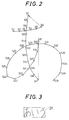
- Fig. 2 is a diagram for explaining stroke data.
- a character as shown in Fig. 2 is written on the touch panel 8 of the handwritten character input/display apparatus 1, the coordinate values of the position of the pen 11 at its XY coordinates are obtained in the above procedure. That is, when stroking along the written character, coordinate values of coordinate points S1 to S36 are sequentially obtained.
- These coordinate values consist of contact-free moving of the pen 11 and touch panel (called pen up hereinafter), and moving while contacting with the pen 11 (called pen down hereinafter). For example, all moves of coordinate points S1, S2, S3 are pen down, and moves from coordinate point S6 to coordinate point S7 are pen up.
- a set of such coordinate data and additional information when moving the coordinates such as up and down of pen 11 is called stroke data.
- stroke data By storing the stroke data, the move of the pen 11 can be easily reproduced on the display panel 6.
- Reproduction on display is moving along the coordinate points S1 to Sn by straight line, that is, it is to approximate traces of handwritten character by straight line.
- the coordinate values of coordinate points S1 to Sn are expressed either by absolute coordinates defining a certain point as the origin (hereinafter called absolute coordinate expression), or by difference from preceding coordinate points (hereinafter called relative coordinate expression).
- absolute coordinate expression defining a certain point as the origin
- relative coordinate expression a vector expression having a moving stroke of +3 in the X-coordinate and -2 in the Y-coordinate in the relative coordinate expression.
- the relative coordinate expression is easier to magnify and reduce as compared with the absolute coordinate expression, and it is generally employed widely.
- the absolute coordinate expression and relative coordinate expression can be mutually transformed. The invention does not depend on the method of expression of coordinate values of stroke data.
- Stroke data can be displayed in a rectangle (quadrangle) 31 for circumscribing the stroke data.
- This rectangle 31 is expressed as rectangular region of stroke data, and the dimensions of the rectangle 31 in X and Y direction may be stored by adding to the stroke data.
- the origin of coordinates stroke data is often set at one of four corners of the rectangle 31.
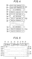
- Fig. 4 is a diagram showing a data composition example of stroke data.
- Start point coordinate (X) 32 and start point coordinate (Y) 33 show coordinates of the start point of stroke data.
- the coordinates show, by defining the origin preliminarily, for example, so as to show the coordinates on the XY coordinates on the origin of the lower left corner of the rectangular region of the stroke data shown in Fig. 3, the moving length of the pen 11 to the start position by departing from the input surface, from this origin.
- the start point coordinates (X), (Y) 32, 33 the coordinate point S1 shown in Fig. 2 is specified.
- Pen information 34 is composed of information whether the pen 11 moves away from the touch panel 6 or moves in contact with the input surface, information showing thickness of the pen, or information showing final coordinate point.
- the relative coordinate (X) 35 and relative coordinate (Y) 36 show the relative moving length of the pen 11 from one coordinate point before in the X-direction and Y-direction as converted to the rectangular coordinates of the input surface.
- the coordinate points S2 to Sn are specified by the pen information 34 and relative coordinates (X), (Y) 35, 36.
- a mark (flag) showing that this coordinate point is final is set in the pen information 34.
- the coordinates are expressed by the coordinate values on the XY coordinates with the origin at the lower left corner of the rectangular region of the stroke data.
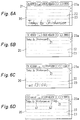
- Fig. 5 is a plan view showing the initial picture displayed on the display panel 6.
- Figs. 6A to 6D are plan views showing in progressive steps an example of the display image at the time of inputting and displaying of handwritten characters.
- a plurality of buttons 12 to 19, 24, 25 are displayed in addition to the input/display area 20 for characters.
- a plurality of ruled lines 22 are displayed at equal intervals.
- a line 23 exists between adjacent ruled lines 22 and a plurality of lines 23 are formed with a plurality of ruled lines 22.
- the cursor 21 indicating the input display position is displayed.
- characters are input in handwriting using the input pen 11.
- the image data inputted in handwriting is submitted to processing for turning into stroke data and then submitted to normalization to be inputted in the right direction in the picture in Fig. 5 from the position where the cursor 21 is displayed.
- the image data is submitted to processing for turning into stroke data and also submitted to normalization, and the characters are displayed in the right direction in the picture in Fig. 6B from the position of the cursor 21 displayed in the forefront position as shown in Fig. 6B.
- the cursor 21 is displayed after the characters displayed.
- the characters which were displayed in the input position are erased.
- the processing for turning into stroke data is one made for reducing the data volume by detecting the necessary image data only from among the sample image data.
- normalization means processing for converting characters inputted in handwriting to a size corresponding to the width of the line 23.
- the image data inputted during the period from the end of processing for turning into stroke data to the next processing for turning into stroke data is treated as forming one block data.
- the image data inputted during the period from the showing of the initial picture to the first processing for turning into stroke data is treated as forming one block data.
- "today, by Sinkansen” and “at 13:00" become single block data respectively and are displayed as block 41 and block 42.
- the processing for turning into stroke data and the processing for normalization are performed for each block.
- processing for turning into stroke data and processing for normalization are performed by indicating the W button 12.
- processing for turning into stroke data and processing for normalization are performed by measuring the time after the end of input in handwriting when there is no input even with the passing of a prescribed time.
- processing for turning into stroke data and processing for normalization are performed when the inputted image data is away from the image data inputted immediately before by no less than the predetermined distance.
- the cursor 21 moves to the indicated position.
- a line feed code is inputted before the block data of the indicated block and a line feed is made at that position.
- the eraser button 15 When, after indicating the eraser button 15 with the input pen 11, a desired position inside the block displayed in the input/display area 20 for characters is indicated, the block data of the indicated block is erased. The erased area becomes blank.
- the eraser button 15 is converted to the pencil button which is not illustrated.
- the block data of the indicated block is deleted.
- the blocks after the erased block are displayed by eliminating the erased space.
- a blank of the predetermined size is deleted.
- the delete button 16 is converted to the pencil button which is not illustrated.
- a plurality of block data and line feed code, etc. are registered as an independent data in the RAM 4 together with the date of input, for example. After the registration is over, the independent data registered in the immediately previous position is read out and displayed in the input/display area 20 for characters. When there is no independent data in the immediately previous position, no processing is made.
- the registration button 18 is indicated with the input pen 11, a plurality of block data and line feed code, etc. are registered as an independent data in the RAM 4 together with the date of input, etc. After the registration is over, the independent data registered in the next position is read out and displayed in the input/display area 20 for characters. When there is no independent data in the next position, the initial picture 26 is displayed.
- the line 23 in the input/display area 20 for characters is sequentially fed and displayed.
- the input/display area 20 for characters is constructed with a plurality (6 in this embodiment) of lines 23a to 23f as shown in Fig. 5 and, if the upper scroll button 24 is indicated with the input pen 11 when the input/display area 20 for characters is being displayed, for example, the input/display area 20 for characters constructed with 6 lines or the 2nd line 23b to the 6th line 23f and the 7th line following the 6th line 23f, is displayed.
- the button 24 is indicated in succession, the input/display area 20 for characters constructed with the 3rd line 23c to the 8th line is displayed.
- the input/display area 20 for characters constructed with the 2nd line 23b to the 7th line is displayed.
- the number of lines for one scrolling may be either 1 line or 2 or more lines.
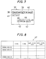
- ⁇ stroke data display coordinate table As an example of stroke data display coordinate table, as shown in Fig. 8, coordinate position 46, X-direction size 44, and Y-direction size 45 displayed in each displayed stroke data are stored.
- the coordinate position 46 is an upper left coordinate point of rectangular regions 38 to 43 expressed in the X,Y direction size 44, 45.
- the coordinate values can be judged, and therefore the stroke data containing the coordinates touched by the pen can be easily specified on the basis of the stroke data display coordinate tables 47, 48.
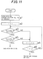
- Fig. 11 is a flowchart for judging which stroke data has been touched by the pen.
- this flowchart an example of using the stroke data display coordinate table 48 shown in Fig. 9 is explained.
- step s1 the coordinates Xp, Yp touched by the pen are obtained.
- step a3 it is judge if coordinate Xp is contained in a range from left end to right end of the i-th stroke data or not. The process moves to step a4 when contained, or to step a5 when not contained.
- step a4 it is judge if coordinate Yp is contained in a range from upper end to lower end of the i-th stroke data or not.
- the instructed stroke data is judged to be data DSi, or the process moves to step a5 when not contained.
- step a5 1 is added to parameter i, and the process moves to step a6.
- step a6 it is judged if parameter i is larger than number n of the displayed stroke data. If judged negatively, the process returns to step a3, and if judged affirmatively, it is judged that the pen 11 does not touch any stroke data.
- the instructed stroke data number is supposed to be SDn, the display coordinates to be (xn, yn), the size of the rectangular region in X-direction to be Wxn, and the size in Y-direction to be Wyn.
- Fig. 12 is a diagram for explaining a case of dividing stroke data into two sections.
- each stroke data is supposed to be displayed in the input size, and the coordinates and size to be displayed in the state of original data. If the display is magnified or reduced from the original data in order to standardize the display size, calculation is possible by taking into consideration the magnifying rate or reducing rate.
- the user specifies the stroke data to be divided.
- Several methods of specifying may be considered, and herein, as shown in Fig. 12A, the top of the display input screen displaying the stroke data 51 is touched by the pen 11.
- the rectangular region 52 containing the specified stroke data 51 is, for example, highlighted, so that the completion of specifying may be seen by the user.
- the stroke data 51 can be divided into two stroke data 53, 54 as shown in Fig. 12C.
- the dividing boundary line is a vertical line including the touched coordinates.
- the coordinates (Zx, Zy) touched for specifying the division boundary line can be judged on the basis of the signal from the touch panel in the same procedure as above.
- Wx is the size of the objective stroke data 51 in the X-direction of the rectangular region 52.
- a specific example of dividing stroke data into stroke data A and stroke data B is described below.
- plural line segments composing stroke data there is only one line segment crossing the boundary line to be divided by pen touch in one case, and there are a plurality in other case, and the single case is described first.
- the absolute coordinate is determined by defining the origin in the upper left corner of the rectangular region of the stroke data.
- a line segment intersecting with the boundary line Kx is searched. That is, taking note of each absolute X-coordinate of start point (Xsn, Ysn) and end point (Xen, Yen) of line segment Sn, the line segment Sn satisfying Kx - Xsn > 0, and Xen - Kx > 0, or the line segment Sn satisfying Kx - Xen > 0, and Xsn - Kx > 0 is searched.
- stroke data 55 shown in Fig. 14A it corresponds to line segment S10.
- the start point (Xsn, Ysn) of the line segment Sn is the end point of stroke data A
- its end point (Xen, Yen) is start point of stroke data B.
- Rectangular regions 57, 58 of stroke data A, B are newly created.
- the start point (Xen, Yen) of stroke data B must be converted to the coordinate values having the origin in the stroke data B because the upper left corner of the rectangular region 58 of the newly created stroke data B is the origin.
- the relative coordinate data may be used again.
- the data after the line segment S (n+1) as constituent element of stroke data B may be directly used as data of stroke data B as far as the coordinate values are relative.
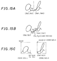
- this line segment Sn is divided into three line segments as shown in Fig. 15B for the sake of convenience, that is: pen down line segment S1n of start point (Xsn, Ysn) and end point (Kx, Kyn) pen up line segment S2n of start point (Kx, Kyn) and end point (Kx, Kyn) (start point and end point are same position) pen down line segment S3n of start point (Kx, Kyn) and end point (Xen, Yen)
- the coordinates are absolute coordinates.
- the coordinates (Kx, Kyn) are processed as end point of stroke data A and start point of stroke data B, and stroke data A and B are obtained as shown in Fig. 15C.
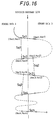
- Fig. 16 shows a case of a plurality of line segments crossing the division boundary line.
- the line segments are expressed by reference numerals Sc1, Sc2, ..., Scn.
- the system of coordinates may be either relative coordinates or absolute coordinates unless otherwise specified.
- the crossing direction of boundary line is same in all odd-numbered line segments Sc1, Sc3, Sc5, etc., and same in all even-numbered line segments Sc2, Sc4, Sc6, etc.
- stroke data B the data from line segment S(c1+1) to line segment S(c2-1) is data of stroke data B, and start point (Xec1, Yec1) is the start point of stroke data B.
- line segment Sc2 start point (Xsc2, Ysc2) and end point (Xec2, Yec2)
- line segment Sc3 start point (Xsc3, Ysc3) and end point (Xec3, Yec3)
- the pen up line segment of line segment Sq2 start point (Xsc2, Ysc2) and end point (Xec3, Yec3) is added next to the line segment S(c2-1) of stroke data B. That is, stroke data B is a line segment row of line segments S(c1+1) to S(c2-1), Sq2, S(c3+1), and so forth.
- stroke data A the data from line segment S(c2+1) to line segment S(c3-1) is data of stroke data A. That is, stroke data A is a line segment row of line segments S1 to S(c1-1), Sq1, S(c2+1) to S9c3-1).
- line segment Sc3 start point (Xsc3, Ysc3) and end point (Xec3, Yec3)
- line segment Sc4 start point (Xsc4, Ysc4) and end point (Xec4, Yec4)
- the pen up line segment of line segment Sq3: start point (Xsc3, Ysc3) and end point (Xec4, Yec4) is added next to the line segment S(c3-1) of stroke data A. That is, stroke data A is a line segment row of line segments S1 to S(c1-1), Sq1, S(c2+1) to S(c3-1), Sq3, S(c3+1), and so forth.
- stroke data B data from line segment S(c3+1) to line segment S(c4-1) is data of stroke data B. Such processing is repeated up to line segment Scn.
- the stroke data can be divided into stroke data row A: S1 to S(c1-1), Sq1, S(c2+1) to S(c3-1), Sq3, S(c4+1), ..., and stroke data row B: S(c1+1) to S(c2-1), Sq2, S(d3+1), S(c4-1), Sq4, S(c5+1), ....
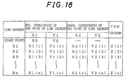
- Fig. 17 is a flowchart explaining division process of stroke data.
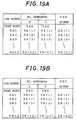
- master stroke data shown in Fig. 18 is divided into stroke data A and stroke data B shown respectively in Figs. 19A and 19B.
- both numerical values of relative coordinates X1, Y1 and absolute coordinates X2, Y2 are prepared by prior processing for the ease of handling.
- the master stroke data in Fig. 18 is divided by boundary line Kx, crossing over the division boundary line Kx in the pen up state only, in the case explained below.
- Step b1 is for initial setting.
- the X absolute coordinate value of the division boundary line is set in coordinate Kx.
- the start point XA0, YA0 of stroke data A is set at start point X0, Y0 of master stroke data.
- Parameters i, j are both set at 1, and parameter m is set at 0, and parameter ST showing to which data the stroke data belongs is set at A.
- step b2 it is judged if line segment Si has crossed the division boundary line or not.
- the process moves to step b3 if not crossing, or advances to step b8 if crossing.
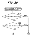
- Specific processing at step b2 is shown in Fig. 20. Referring to Fig. 20, at step b21, it is judged if the absolute coordinate value X2(i) of end point of line segment Si is greater than coordinate value Kx, and if the absolute coordinate value X2(i-1) of end point of line segment S(i-1) is smaller than coordinate value Kx. If judged affirmatively, it is estimated that the line segment Si has crossed the division boundary line. If judged negatively at step b21, the process moves to step b22.
- step b22 it is judged if the absolute coordinate value X2(i) of end point of line segment Si is smaller than coordinate value Kx, and if the absolute coordinate value X2(i-1) of end point of line segment S(i-1) is greater than coordinate value Kx. If judged affirmatively, it is estimated that the line segment Si has crossed the division boundary line. If judged negatively, it is estimated that the line segment Si has not crossed the division boundary line.
- step b3 it is judged if parameter ST is A or not. If judged affirmatively, the process moves to step b4, and if judged negatively, the process moves to step b5.
- step b4 relative coordinate values X1(i), Y1(i) and pen information Z(i) of end point about line segment Si are stored respectively as relative coordinate values XA(j), YA(j), and ZA (j) of end point about line segment SAj for composing stroke data A, and 1 is added to parameter j, and the process moves to step b6.
- step b5 relative coordinate values X1(i), Y1(i) and pen information Z(i) of end point about line segment Si are stored respectively as relative coordinate values XB(m), YB(m), and ZB (m) of end point about line segment SBm for composing stroke data B, and 1 is added to parameter m, and the process moves to step b6.
- step b6 1 is added to parameter i, and at step b7, it is judged if parameter i is greater than the number n of line segments for composing the master stroke data. If greater, the process is over, and if not greater, the process returns to step b2, and next line segment is processed similarly.
- step b11 the start point XB0, YB0 of stroke data B is set. More specifically, the value subtracting the coordinate value Kx from the absolute X-coordinate X2 (i) of end point of line segment Si is set at X-coordinate XB0 of start point of stroke data B, and absolute Y-coordinate Y2(i) of end point of line segment Si is set at Y-coordinate YB0 of start point.
- step b12 parameter m is set at 1, and the process moves to step b14.
- step b13 relative coordinates XB(m), YB(m), and pen information ZB(m) of end point about line segment SBm for composing stroke data B are set, 1 is added to parameter m, and the process moves to step b14. More specifically, the relative X-coordinate value XB(m) of end point of line segment SBm is set at a value of subtracting the coordinate value Xp set at subsequent step b14 from the absolute X-coordinate value X2(i) at end point of line segment Si.
- the relative Y-coordinate value YB(m) of end point of line segment SBm is set at a value of subtracting the coordinate value Yp set at subsequent step b14 from the absolute Y-coordinate value Y2(i) at end point of line segment Si.
- the pen information ZB(m) of line segment SBm is set at "up.”
- the coordinate value Xp is set at absolute X-coordinate value X2(i-1) of end point of line segment S(i-1), and the coordinate value Yp is set at absolute Y-coordinate value Y2(i-10) of end point of line segment S(i-1), and the process moves to step b6.
- step b16 relative coordinates XA(j), YA(j), and pen information ZA(j) of end point about line segment SAj for composing stroke data A are set, 1 is added to parameter j, and the process moves to step b14. More specifically, the relative X-coordinate value XA(j) of end point of line segment SAj is set at a value of subtracting the coordinate value Xp set at preceding step b14 from the absolute X-coordinate value X2(i) at end point of line segment Si.
- the relative Y-coordinate value YA(j) of end point of line segment SAj is set at a value of subtracting the coordinate value Yp set at preceding step b14 from the absolute Y-coordinate value Y2(i) at end point of line segment Si.
- the pen information ZA(j) of line segment SAj is set at "up.”
- the master stroke data shown in Fig. 18 is divided into stroke data A and stroke data B as shown respectively in Figs. 19A and 19B.
- the stroke data is displayed again on the display screen. In this case, a slight gap may be formed between stroke data A and stroke data B so that the vision may be easier to see by the user.
- Fig. 21 is a diagram for explaining the process of deleting part of stroke data. This explanation is an example of deletion action, and it is not limited by this operation only.
- the manipulation to be done is instructed to be deletion action in the input/display apparatus 1.
- the objective stroke data 71 is specified by the pen 11.
- the coordinates of the position touched by the pen 11 in the stroke data 71 specified by the pen 11 are determined. This is realized in the same method as in the foregoing embodiment.
- the objective stroke data 71 is judged, it is noticed by the user by, for example, highlighting the stroke data 71 as shown in Fig. 21B.
- the stroke data 71 is divided and displayed as two stroke data 73, 74 according to the division method of stroke data mentioned above as shown in Fig. 21D. Consequently, either specified side of divided stroke data 73, 74, for example, stroke data 74 is deleted, and when next stroke data 75 is displayed successively to the deleted stroke data 74, it may be displayed by filling up the vacancy as shown in Fig. 21E.
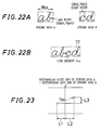
- Fig. 22 is a diagram for explaining a combining method of stroke data.
- stroke data A and stroke data B to be combined are specified by touching by the pen 11 or other method.
- stroke data A and stroke data B are supposed to be identical in size in Y-direction of the rectangular regions. If not of same size, either stroke data A or B, or both must be integrated, and the Y-direction must be preliminarily reduced or magnified to a specific size. This integration process can be easily done as far as the stroke data is expressed in the system of relative coordinates.
- a new pen up line segment Ssp is defined so as to link end point (Xan, Yan) (absolute coordinates) of stroke data A, and start point (Xb1, Yb1) (absolute coordinates) of stroke data B (however, the origin of coordinates being different from stroke data A) (see Fig. 22B).
- Fig. 24 is a flowchart explaining the combining process of stroke data.
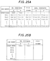
- stroke data A and stroke data B shown in Figs. 25A and 25B are combined into stroke data shown in Fig. 26.
- the rectangular X-direction size WAX of stroke data has been calculated by prior processing.
- step c1 relative coordinates XA0, YA0 of start point of stroke data A are respectively set as start point coordinates X0, Y0 of combined stroke data.
- step c3 relative coordinate values XA(i), YA(i), and pen information ZA(i) of end point about line segment SAi for composing stroke data A are respectively set as relative coordinate values X(i), Y(i), and pen information Z(i) of end point about line segment Si for composing the combined stroke data. Adding 1 to parameter i, the process moves to step c4.
- step c5 in order to combine stroke data A and stroke data B, line segment Ssp to be newly added is calculated and set.
- the relative Y-coordinate Y(i) of end point of line segment Si is set at a value of (relative Y-coordinate YB0 of start point of stroke data B) - (absolute Y-coordinate Y1An1 of end point of line segment SAn1)
- the pen information Z(i) is set at "up.” Adding 1 to parameter i, the process moves to step c6.
- step c7 relative coordinate values XB(j), YB(j), and pen information ZB(j) of end point about line segment SBj for composing stroke data B are respectively set as relative coordinate values X(i), Y(i), and pen information Z(i) of end point about line segment Si for composing the combined stroke data. Adding 1 to parameters i and j, the process moves to step c9.
- step c9 it is judged if parameter j is greater than the number n2 of line segments for composing stroke data B. If parameter j is not greater than n2, returning to step c7, the line segment SBj for composing stroke data B is sequentially set as line segment Si for composing new stroke data. Processing is over when parameter j is greater than n2.
- Integration process when the size of stroke data A and B differs in the rectangular region as mentioned above is executed as follows.
- the X-direction length is supposed to be Wxa and the Y-direction length to be Wya.
- the X-direction length is supposed to be Wxb, and the Y-direction length to be Wyb.
- Wxa is not equal to Wxb
- Wya is not equal to Wyb.
- stroke data B is integrated into stroke data A.
- the reducing or magnifying rate is determined on the basis of the Y-direction length. That is, Wya/Wyb is determined.
- stroke data B is integrated into stroke data A.
- stroke data A it is similarly realized, or the stroke data A and B may be reduced or magnified at different ratio, and integrated.
- the stroke data is composed by containing attribute data as additional information, that is, data showing thickness of characters and data showing type of line, aside from the coordinate data and additional information showing the pen state as explained in Fig. 2. Therefore, when combining, attribute data of either one stroke data should be matched with attribute data of other stroke data.
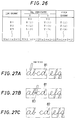
- Fig. 27 is a diagram for explaining the action for inserting a blank in the stroke data.
- the manipulation to be done here is instructed to be blank insertion action to the input/display apparatus 1 preliminarily by display button or key manipulation or other manipulation.
- the blank size to be inserted is too be specified preliminarily by numerals in dot units.
- the objective stroke data 81 is specified by the pen 11, and then, as shown in Fig. 27B, the place for inserting the blank is specified again by pen touch in the stroke data 81.
- Fig. 27C specified blank is inserted in specified position of the specified stroke data 81, and hence it is changed and displayed as new stroke data 82.
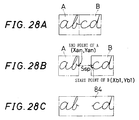
- the coordinates of the stroke data 81 specified by the pen 11 and the point 83 touched by the pen 11 are determined. This is realized by the same method as in the foregoing embodiments, and the objective stroke data 81 and the point 83 in the stroke data can be determined. Defining the coordinates of the pen touched by the pen 11 as boundary line, the stroke data 81 is divided into stroke data A and stroke data B as shown in Fig. 28A according to the division method of stroke data mentioned above. For the sake of simplicity of explanation, the divided data is supposed to be transformed into relative coordinates.
- the stroke data A contains the start point of the stroke data 81.
- a new pen up segment Ssp is defined so as to link the end point (Xan, Yan) (absolute coordinates) of the divided stroke data A, and the start point (Xb1,Yb1) (absolute coordinates, however, the origin of coordinate being different from stroke data A) of stroke data B.
- the relative coordinates of this pen up line segment Ssp are defined as follows: relative X-coordinate: (length of coordinate Xan and rectangular right end of stroke data A) + (length of Xb1 and rectangular left end of stroke data B) + (specified blank dot size) relative Y-coordinate: (coordinate Yb1 - coordinate Yan)
- This line segment Ssp is added to the end of stroke data A.
- line segments Sb1 to Sbm of stroke data B are added. Being expressed in relative coordinates, it is easy to add.
- the new stroke data 84 combined with the line segment Ssp and stroke data B is the intended stroke data in which the blank is inserted. Afterwards, the new stroke data is displayed again on the display screen, and is depicted as shown in Fig. 28C.
- Fig. 29 is a diagram for explaining insertion processing of stroke data. Creation of new stroke data by inserting other stroke data into certain stroke data is realized by combining the division processing and combination processing of stroke data mentioned above. First, as shown in Fig. 29A, stroke data D to be inserted is specified. Then inserting stroke data C is specified. Stroke data can be specified in the same method as above. The specified stroke data D, C are read out from the RAM 4, normalized, and temporarily stored in the memory region.
- the inserting position of the inserting stroke data C is specified by using the pen 11.
- the insertion position in the objective stroke data can be obtained.
- the stroke data D is divided into stroke data A and stroke data B, and the inserting stroke data C is moved in between the stroke data A and stroke data B as shown in Fig. 29C, and first as shown in Fig. 29D, the stroke data A and stroke data C are combined to make up stroke data E, then, as shown in Fig. 29E, the combined new stroke data E and stroke data B are further combined to make up stroke data F. As a result, the stroke data C is inserted into the stroke data D.
Landscapes
- Engineering & Computer Science (AREA)
- General Engineering & Computer Science (AREA)
- Theoretical Computer Science (AREA)
- Human Computer Interaction (AREA)
- Physics & Mathematics (AREA)
- General Physics & Mathematics (AREA)
- User Interface Of Digital Computer (AREA)
- Processing Or Creating Images (AREA)
- Character Discrimination (AREA)
- Document Processing Apparatus (AREA)
Applications Claiming Priority (3)
| Application Number | Priority Date | Filing Date | Title |
|---|---|---|---|
| JP34009194 | 1994-12-29 | ||
| JP6340091A JP2939147B2 (ja) | 1994-12-29 | 1994-12-29 | 手書き文字入力表示装置および方法 |
| JP340091/94 | 1994-12-29 |
Publications (3)
| Publication Number | Publication Date |
|---|---|
| EP0720084A2 true EP0720084A2 (de) | 1996-07-03 |
| EP0720084A3 EP0720084A3 (de) | 1997-09-10 |
| EP0720084B1 EP0720084B1 (de) | 2002-02-27 |
Family
ID=18333633
Family Applications (1)
| Application Number | Title | Priority Date | Filing Date |
|---|---|---|---|
| EP95120734A Expired - Lifetime EP0720084B1 (de) | 1994-12-29 | 1995-12-29 | Eingabe- und Anzeigegerät für Handschrift |
Country Status (5)
| Country | Link |
|---|---|
| US (1) | US5850477A (de) |
| EP (1) | EP0720084B1 (de) |
| JP (1) | JP2939147B2 (de) |
| CN (1) | CN1110765C (de) |
| DE (1) | DE69525606T2 (de) |
Cited By (4)
| Publication number | Priority date | Publication date | Assignee | Title |
|---|---|---|---|---|
| CN101799735B (zh) * | 2009-02-10 | 2013-04-10 | Tcl集团股份有限公司 | 一种原笔迹手写输入显示方法 |
| WO2017032459A1 (en) * | 2015-08-25 | 2017-03-02 | Myscript | System and method of digital note taking |
| US9965175B2 (en) | 2015-08-25 | 2018-05-08 | Myscript | System and method of digital note taking |
| US10410316B2 (en) | 2015-12-08 | 2019-09-10 | Myscript | System and method for beautifying digital ink |
Families Citing this family (45)
| Publication number | Priority date | Publication date | Assignee | Title |
|---|---|---|---|---|
| US5838302A (en) * | 1995-02-24 | 1998-11-17 | Casio Computer Co., Ltd. | Data inputting devices for inputting typed and handwritten data in a mixed manner |
| US6049329A (en) * | 1996-06-04 | 2000-04-11 | International Business Machines Corporartion | Method of and system for facilitating user input into a small GUI window using a stylus |
| JPH10326146A (ja) * | 1997-05-23 | 1998-12-08 | Wacom Co Ltd | 座標入力用器具 |
| US6108444A (en) * | 1997-09-29 | 2000-08-22 | Xerox Corporation | Method of grouping handwritten word segments in handwritten document images |
| US6898315B2 (en) * | 1998-03-23 | 2005-05-24 | Microsoft Corporation | Feature extraction for real-time pattern recognition using single curve per pattern analysis |
| US6333994B1 (en) * | 1999-03-31 | 2001-12-25 | International Business Machines Corporation | Spatial sorting and formatting for handwriting recognition |
| US6731803B1 (en) * | 1999-07-12 | 2004-05-04 | Advanced Recognition Technologies, Ltd | Points based handwriting recognition system |
| JP3974359B2 (ja) * | 2000-10-31 | 2007-09-12 | 株式会社東芝 | オンライン文字認識装置及び方法並びにコンピュータ読み取り可能な記憶媒体及びオンライン文字認識プログラム |
| JP3554271B2 (ja) * | 2000-12-13 | 2004-08-18 | パナソニック コミュニケーションズ株式会社 | 情報通信装置 |
| US6658147B2 (en) * | 2001-04-16 | 2003-12-02 | Parascript Llc | Reshaping freehand drawn lines and shapes in an electronic document |
| US7096432B2 (en) * | 2002-05-14 | 2006-08-22 | Microsoft Corporation | Write anywhere tool |
| KR100713407B1 (ko) * | 2002-11-18 | 2007-05-04 | 삼성전자주식회사 | 펜 컴퓨팅 시스템에서의 펜 입력 방법 및 장치 |
| WO2004068331A1 (ja) * | 2003-01-30 | 2004-08-12 | Fujitsu Limited | 手書き入力装置及び方法 |
| US7185291B2 (en) * | 2003-03-04 | 2007-02-27 | Institute For Information Industry | Computer with a touch screen |
| US7657094B2 (en) * | 2005-12-29 | 2010-02-02 | Microsoft Corporation | Handwriting recognition training and synthesis |
| US7720316B2 (en) * | 2006-09-05 | 2010-05-18 | Microsoft Corporation | Constraint-based correction of handwriting recognition errors |
| CN101295217B (zh) * | 2008-06-05 | 2010-06-09 | 中兴通讯股份有限公司 | 手写输入处理装置和方法 |
| CN101833411B (zh) * | 2009-03-09 | 2015-09-16 | 诺基亚公司 | 用于笔迹输入的方法和设备 |
| KR20100124426A (ko) * | 2009-05-19 | 2010-11-29 | 삼성전자주식회사 | 아날로그 입력 가능한 컴퓨팅 기기에서 손 글씨 저장 장치 및 방법 |
| CN102136153B (zh) * | 2010-01-22 | 2016-05-25 | 腾讯科技(深圳)有限公司 | 一种用于即时通信工具的图片处理的方法及装置 |
| KR101486174B1 (ko) * | 2010-08-24 | 2015-01-23 | 노키아 코포레이션 | 중첩된 수기의 획들을 하나 이상의 그룹으로 분할하는 방법 및 장치 |
| US8669995B2 (en) * | 2010-10-08 | 2014-03-11 | Adobe Systems Incorporated | Methods and apparatus for stroke grouping for high-level sketch editing |
| US8952905B2 (en) * | 2011-01-30 | 2015-02-10 | Lg Electronics Inc. | Image display apparatus and method for operating the same |
| CN102169413A (zh) * | 2011-03-30 | 2011-08-31 | 黄冬明 | 基于视频流图像获得字符笔划线条的装置及方法 |
| JP5694234B2 (ja) * | 2012-05-11 | 2015-04-01 | 株式会社東芝 | 電子機器、手書き文書表示方法、及び表示プログラム |
| JP5248696B1 (ja) * | 2012-05-25 | 2013-07-31 | 株式会社東芝 | 電子機器、手書き文書作成方法、及び手書き文書作成プログラム |
| JP2014071755A (ja) * | 2012-09-28 | 2014-04-21 | Sharp Corp | 編集装置、編集装置の制御方法 |
| US20140105503A1 (en) * | 2012-10-15 | 2014-04-17 | Kabushiki Kaisha Toshiba | Electronic apparatus and handwritten document processing method |
| JP6076026B2 (ja) * | 2012-10-18 | 2017-02-08 | シャープ株式会社 | 表示装置、表示方法、および表示プログラム |
| JP5942835B2 (ja) * | 2012-12-20 | 2016-06-29 | 富士ゼロックス株式会社 | 手書き情報処理装置及びプログラム |
| JP2014133370A (ja) * | 2013-01-10 | 2014-07-24 | Brother Ind Ltd | テープ印字装置及び操作表示方法 |
| US20140232667A1 (en) * | 2013-02-15 | 2014-08-21 | Kabushiki Kaisha Toshiba | Electronic device and method |
| KR20140132171A (ko) * | 2013-05-07 | 2014-11-17 | 삼성전자주식회사 | 터치용 펜을 이용하는 휴대 단말기 및 이를 이용한 필기 입력 방법 |
| US9465985B2 (en) | 2013-06-09 | 2016-10-11 | Apple Inc. | Managing real-time handwriting recognition |
| US9229543B2 (en) * | 2013-06-28 | 2016-01-05 | Lenovo (Singapore) Pte. Ltd. | Modifying stylus input or response using inferred emotion |
| CN104461325A (zh) * | 2013-09-16 | 2015-03-25 | 联想(北京)有限公司 | 一种数据处理方法及电子设备 |
| KR20160062565A (ko) * | 2014-11-25 | 2016-06-02 | 삼성전자주식회사 | 디바이스 및 디바이스의 필기 컨텐트 제공 방법 |
| US10346510B2 (en) * | 2015-09-29 | 2019-07-09 | Apple Inc. | Device, method, and graphical user interface for providing handwriting support in document editing |
| US10324618B1 (en) * | 2016-01-05 | 2019-06-18 | Quirklogic, Inc. | System and method for formatting and manipulating digital ink |
| US10755029B1 (en) | 2016-01-05 | 2020-08-25 | Quirklogic, Inc. | Evaluating and formatting handwritten input in a cell of a virtual canvas |
| DK179329B1 (en) | 2016-06-12 | 2018-05-07 | Apple Inc | Handwriting keyboard for monitors |
| US9977976B2 (en) * | 2016-06-29 | 2018-05-22 | Konica Minolta Laboratory U.S.A., Inc. | Path score calculating method for intelligent character recognition |
| CN109147004B (zh) * | 2018-08-20 | 2023-06-09 | 广州视源电子科技股份有限公司 | 笔迹显示方法、装置、设备及存储介质 |
| CN110069205A (zh) * | 2019-04-15 | 2019-07-30 | 广州视源电子科技股份有限公司 | 一种书写轨迹调整的方法、装置、终端设备和存储介质 |
| US11194467B2 (en) | 2019-06-01 | 2021-12-07 | Apple Inc. | Keyboard management user interfaces |
Family Cites Families (20)
| Publication number | Priority date | Publication date | Assignee | Title |
|---|---|---|---|---|
| JPS6249483A (ja) * | 1985-08-28 | 1987-03-04 | Hitachi Ltd | 実時間手書き文字認識の文字入力方式 |
| JPS6079485A (ja) * | 1983-10-06 | 1985-05-07 | Sharp Corp | 手書き文字認識処理装置 |
| US4731857A (en) * | 1984-06-29 | 1988-03-15 | International Business Machines Corporation | Recognition system for run-on handwritten characters |
| CA1223366A (en) * | 1984-09-27 | 1987-06-23 | Abijah S. Fox | System for automatic adjustment and editing of handwritten text images |
| US4680803A (en) * | 1984-12-17 | 1987-07-14 | Ncr Corporation | Method and apparatus for isolating image data for character recognition |
| JPS621086A (ja) * | 1985-06-26 | 1987-01-07 | Toshiba Corp | 文字入力装置 |
| US5046114A (en) * | 1985-10-01 | 1991-09-03 | The Palantir Corporation | Method and structure for separating joined patterns for use in pattern and character recognition system |
| JPH0622028B2 (ja) * | 1986-03-29 | 1994-03-23 | 株式会社東芝 | 文書作成編集装置 |
| US4972496A (en) * | 1986-07-25 | 1990-11-20 | Grid Systems Corporation | Handwritten keyboardless entry computer system |
| US4953225A (en) * | 1987-10-16 | 1990-08-28 | Sharp Kabushiki Kaisha | Handwritten character-recognizing apparatus for automatically generating and displaying character frames |
| US5220649A (en) * | 1991-03-20 | 1993-06-15 | Forcier Mitchell D | Script/binary-encoded-character processing method and system with moving space insertion mode |
| JPH0528317A (ja) * | 1991-07-23 | 1993-02-05 | Canon Inc | 画像処理方法及び装置 |
| JP2691101B2 (ja) * | 1992-03-05 | 1997-12-17 | インターナショナル・ビジネス・マシーンズ・コーポレイション | 手書き入力方法及び入力装置 |
| JP3260843B2 (ja) * | 1992-08-25 | 2002-02-25 | 株式会社リコー | 文字認識方法 |
| US5448475A (en) * | 1992-11-18 | 1995-09-05 | Sharp Kabushiki Kaisha | Word processing apparatus with handwriting input function |
| US5613019A (en) * | 1993-05-20 | 1997-03-18 | Microsoft Corporation | System and methods for spacing, storing and recognizing electronic representations of handwriting, printing and drawings |
| US5517578A (en) * | 1993-05-20 | 1996-05-14 | Aha! Software Corporation | Method and apparatus for grouping and manipulating electronic representations of handwriting, printing and drawings |
| US5500937A (en) * | 1993-09-08 | 1996-03-19 | Apple Computer, Inc. | Method and apparatus for editing an inked object while simultaneously displaying its recognized object |
| US5583946A (en) * | 1993-09-30 | 1996-12-10 | Apple Computer, Inc. | Method and apparatus for recognizing gestures on a computer system |
| JP2939119B2 (ja) * | 1994-05-16 | 1999-08-25 | シャープ株式会社 | 手書き文字入力表示装置および方法 |
-
1994
- 1994-12-29 JP JP6340091A patent/JP2939147B2/ja not_active Expired - Lifetime
-
1995
- 1995-12-28 US US08/580,327 patent/US5850477A/en not_active Expired - Lifetime
- 1995-12-29 EP EP95120734A patent/EP0720084B1/de not_active Expired - Lifetime
- 1995-12-29 DE DE69525606T patent/DE69525606T2/de not_active Expired - Lifetime
- 1995-12-29 CN CN95113169A patent/CN1110765C/zh not_active Expired - Lifetime
Cited By (4)
| Publication number | Priority date | Publication date | Assignee | Title |
|---|---|---|---|---|
| CN101799735B (zh) * | 2009-02-10 | 2013-04-10 | Tcl集团股份有限公司 | 一种原笔迹手写输入显示方法 |
| WO2017032459A1 (en) * | 2015-08-25 | 2017-03-02 | Myscript | System and method of digital note taking |
| US9965175B2 (en) | 2015-08-25 | 2018-05-08 | Myscript | System and method of digital note taking |
| US10410316B2 (en) | 2015-12-08 | 2019-09-10 | Myscript | System and method for beautifying digital ink |
Also Published As
| Publication number | Publication date |
|---|---|
| DE69525606T2 (de) | 2002-10-24 |
| JP2939147B2 (ja) | 1999-08-25 |
| CN1110765C (zh) | 2003-06-04 |
| CN1131773A (zh) | 1996-09-25 |
| DE69525606D1 (de) | 2002-04-04 |
| JPH08185398A (ja) | 1996-07-16 |
| EP0720084B1 (de) | 2002-02-27 |
| EP0720084A3 (de) | 1997-09-10 |
| US5850477A (en) | 1998-12-15 |
Similar Documents
| Publication | Publication Date | Title |
|---|---|---|
| US5850477A (en) | Input and display apparatus with editing device for changing stroke data | |
| US4860372A (en) | Real time handwritten character input system | |
| US5867158A (en) | Data processing apparatus for scrolling a display image by designating a point within the visual display region | |
| US20180024719A1 (en) | User interface systems and methods for manipulating and viewing digital documents | |
| US20090063960A1 (en) | User interface systems and methods for manipulating and viewing digital documents | |
| JPH07146951A (ja) | 文書作成装置 | |
| JPS6075873A (ja) | 表示装置 | |
| JPS6289990A (ja) | 作表装置 | |
| JP2021018721A (ja) | 描画順序決定方法、描画方法および描画装置 | |
| JP3268029B2 (ja) | 手書き入力装置 | |
| JPS63174125A (ja) | フアイル検索装置 | |
| JPH08202856A (ja) | 画像処理方法 | |
| JPH0346081A (ja) | オンライン手書文字入力方法 | |
| JPH0565903B2 (de) | ||
| JPS597992A (ja) | マルチウインドウ画面によるデイスプレイ表示方式 | |
| JPS63313234A (ja) | フアイルインデツクス表示方式 | |
| JPH0128981B2 (de) | ||
| Hodes | A programming system for the on-line analysis of biomedical images | |
| JPH06325144A (ja) | レイアウトデザイン装置 | |
| JPH06214982A (ja) | ジェスチャー編集機能付き文書処理装置 | |
| JPS62143189A (ja) | 文書編集方式 | |
| JP3977874B2 (ja) | 文書出力方法および装置 | |
| JPS61180283A (ja) | ワ−ドプロセツサ | |
| JPH04148370A (ja) | 文書処理装置 | |
| JPS6314229A (ja) | オブジエクト選択方式 |
Legal Events
| Date | Code | Title | Description |
|---|---|---|---|
| PUAI | Public reference made under article 153(3) epc to a published international application that has entered the european phase |
Free format text: ORIGINAL CODE: 0009012 |
|
| AK | Designated contracting states |
Kind code of ref document: A2 Designated state(s): DE FR GB |
|
| PUAL | Search report despatched |
Free format text: ORIGINAL CODE: 0009013 |
|
| AK | Designated contracting states |
Kind code of ref document: A3 Designated state(s): DE FR GB |
|
| 17P | Request for examination filed |
Effective date: 19971230 |
|
| 17Q | First examination report despatched |
Effective date: 20000803 |
|
| GRAG | Despatch of communication of intention to grant |
Free format text: ORIGINAL CODE: EPIDOS AGRA |
|
| GRAG | Despatch of communication of intention to grant |
Free format text: ORIGINAL CODE: EPIDOS AGRA |
|
| GRAH | Despatch of communication of intention to grant a patent |
Free format text: ORIGINAL CODE: EPIDOS IGRA |
|
| GRAH | Despatch of communication of intention to grant a patent |
Free format text: ORIGINAL CODE: EPIDOS IGRA |
|
| REG | Reference to a national code |
Ref country code: GB Ref legal event code: IF02 |
|
| GRAA | (expected) grant |
Free format text: ORIGINAL CODE: 0009210 |
|
| AK | Designated contracting states |
Kind code of ref document: B1 Designated state(s): DE FR GB |
|
| REF | Corresponds to: |
Ref document number: 69525606 Country of ref document: DE Date of ref document: 20020404 |
|
| ET | Fr: translation filed | ||
| PLBE | No opposition filed within time limit |
Free format text: ORIGINAL CODE: 0009261 |
|
| STAA | Information on the status of an ep patent application or granted ep patent |
Free format text: STATUS: NO OPPOSITION FILED WITHIN TIME LIMIT |
|
| 26N | No opposition filed |
Effective date: 20021128 |
|
| PGFP | Annual fee paid to national office [announced via postgrant information from national office to epo] |
Ref country code: DE Payment date: 20141211 Year of fee payment: 20 Ref country code: GB Payment date: 20141219 Year of fee payment: 20 |
|
| PGFP | Annual fee paid to national office [announced via postgrant information from national office to epo] |
Ref country code: FR Payment date: 20141219 Year of fee payment: 20 |
|
| REG | Reference to a national code |
Ref country code: DE Ref legal event code: R071 Ref document number: 69525606 Country of ref document: DE |
|
| REG | Reference to a national code |
Ref country code: GB Ref legal event code: PE20 Expiry date: 20151228 |
|
| PG25 | Lapsed in a contracting state [announced via postgrant information from national office to epo] |
Ref country code: GB Free format text: LAPSE BECAUSE OF EXPIRATION OF PROTECTION Effective date: 20151228 |