EP0719983B2 - Verfahren und Vorrichtung zum Zuleiten eines gasförmigen Brennstoffs in einen Vormischbrenner - Google Patents
Verfahren und Vorrichtung zum Zuleiten eines gasförmigen Brennstoffs in einen Vormischbrenner Download PDFInfo
- Publication number
- EP0719983B2 EP0719983B2 EP95810781A EP95810781A EP0719983B2 EP 0719983 B2 EP0719983 B2 EP 0719983B2 EP 95810781 A EP95810781 A EP 95810781A EP 95810781 A EP95810781 A EP 95810781A EP 0719983 B2 EP0719983 B2 EP 0719983B2
- Authority
- EP
- European Patent Office
- Prior art keywords
- fuel
- zone
- premixture
- premixing
- burner
- Prior art date
- Legal status (The legal status is an assumption and is not a legal conclusion. Google has not performed a legal analysis and makes no representation as to the accuracy of the status listed.)
- Expired - Lifetime
Links
Images
Classifications
-
- F—MECHANICAL ENGINEERING; LIGHTING; HEATING; WEAPONS; BLASTING
- F23—COMBUSTION APPARATUS; COMBUSTION PROCESSES
- F23D—BURNERS
- F23D14/00—Burners for combustion of a gas, e.g. of a gas stored under pressure as a liquid
- F23D14/46—Details
- F23D14/62—Mixing devices; Mixing tubes
-
- F—MECHANICAL ENGINEERING; LIGHTING; HEATING; WEAPONS; BLASTING
- F23—COMBUSTION APPARATUS; COMBUSTION PROCESSES
- F23C—METHODS OR APPARATUS FOR COMBUSTION USING FLUID FUEL OR SOLID FUEL SUSPENDED IN A CARRIER GAS OR AIR
- F23C2900/00—Special features of, or arrangements for combustion apparatus using fluid fuels or solid fuels suspended in air; Combustion processes therefor
- F23C2900/07002—Premix burners with air inlet slots obtained between offset curved wall surfaces, e.g. double cone burners
-
- Y—GENERAL TAGGING OF NEW TECHNOLOGICAL DEVELOPMENTS; GENERAL TAGGING OF CROSS-SECTIONAL TECHNOLOGIES SPANNING OVER SEVERAL SECTIONS OF THE IPC; TECHNICAL SUBJECTS COVERED BY FORMER USPC CROSS-REFERENCE ART COLLECTIONS [XRACs] AND DIGESTS
- Y02—TECHNOLOGIES OR APPLICATIONS FOR MITIGATION OR ADAPTATION AGAINST CLIMATE CHANGE
- Y02E—REDUCTION OF GREENHOUSE GAS [GHG] EMISSIONS, RELATED TO ENERGY GENERATION, TRANSMISSION OR DISTRIBUTION
- Y02E20/00—Combustion technologies with mitigation potential
- Y02E20/34—Indirect CO2mitigation, i.e. by acting on non CO2directly related matters of the process, e.g. pre-heating or heat recovery
Definitions
- the invention relates to a method for feeding a gaseous fuel in a premix burner according to claim 1 and a premix burner for its implementation according to claim 8th.
- the mixing of some of the fuel with part of the combustion air takes place usually immediately after the mixture has escaped from the premix zone, i.e. the composition the fuel / primary air mixture is so chosen that it lies within the ignition limit. The remaining air and possibly the remaining fuel fed directly to the flame.
- premix burner As a flame-holding burner, which without mechanical flame holder can get by so-called premix burner of the double cone type be designated.
- premix burner of the double cone type are known for example from EP-B1-0 321 809.
- the fuel, there gas, is in the entry columns in the from Combustion air flowing in through a compressor Row of injector nozzles injected. These are in the Usually evenly distributed over the entire gap.
- the composition of the premix provides the necessary security against striking back the flame.
- the new device according to claim 8 has the advantage of simplicity. In contrast to the beginning mentioned device according to EP-A-0 187 441 it is not multiple housings in the new device and lines. Basically, the device both for operation with xx fuel as well to consist of only one housing with yy fuel.
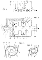
- a premix burner which is essentially a pre-mixing zone VMZ, a final mixing zone EMZ and has a combustion zone VZ.
- At least a first part of a gaseous fuel B is the premix burner via a feed line 4 fed.
- the supply takes place via a main line 10 of oxygen-containing gas G, in the example of air, to the premix zone VMZ in the form of primary gas PG.
- the premixing zone VMZ becomes a premixing VM educated.
- the concentration of fuel in the premix VM will operate under the respective operating conditions of the burner selected so that the premixing is outside the ignition limit.
- the fuel used can be premixed both be too fat as well as lean.
- the concentration of the fuel in the premixing above the ignitability limit is between about 50 and 100%.
- the concentration of the Fuel in the premix below Zündlessgrenze.
- the mass fraction of the fuel in this case the premixing is between about 0 and 2.2%. It is understood that these figures are only guidelines; the exact values depend from the gas type, the combustion air temperature and -pressure at the burner inlet, gas temperature and the Air speed in the burner.
- the premixing VM is then fed to a final mixing zone EMZ, and is mixed therein with the remaining fuel RB, which is likewise supplied, and / with an oxygen-containing secondary gas SG.
- the resulting final mixture EM is fed to a subsequent combustion zone VZ. If necessary, an oxygen-containing tertiary gas TG can be fed to the combustion zone VZ.
- the main line 10 for supplying air to the VMZ mixing zones and EMZ and in the combustion zone VZ of the premix burner is designed with a housing Longitudinal axis X-X.
- First feeding means for feeding Fuel in the premixing zone VMZ is denoted by 4. This is the fuel supply, in a nozzle plate arranged perpendicular to the longitudinal axis 15 flows. The combustion air passes through line 1 into the housing above the nozzle plate 15th
- Feed means 6 serve to forward the premixing VM from the premixing zone VMZ into a final mixing zone RPS.
- shut-off valve V1 With shut-off valve V1 close and open Shut-off device V2 will be close to all of the fuel and some of the air is fed to the premixing zone VMZ.
- This mode of operation is selected for a fuel low calorific value, the mass fraction of the Fuel in the premix between about 50 and is 100%.
- shutoff valve V1 With shutoff valve V1 open and close to closed Shut-off device V2 becomes close to all air and only some of the fuel is fed to the premixing zone VMZ. The remaining fuel becomes the final mixing zone EMZ fed.
- This style of driving is chosen at a Fuel high calorific value, the mass fraction of fuel in the premix between is about 0 and 2.2%.
- Tertiary air TG is fed into the combustion zone VZ by opening the shut-off device V3 accordingly.
- Premix burner 110 is a so-called Double cone burner, such as from EP-B1-0 321 809 is known.
- the lean premixing flows over the tangential slots of the burner into the interior of the burner.
- the in the area of the tangential slots in the walls of the two partial bodies distributed in the longitudinal direction Inflow openings now serve the injection of the residual fuel RB, which over the central fuel lance protruding from the cathedral 5 is introduced.
- the mixture enrichment the lean premixing with the residual fuel RB also begins here in the zone of the entry slots.
Landscapes
- Engineering & Computer Science (AREA)
- Chemical & Material Sciences (AREA)
- Combustion & Propulsion (AREA)
- Mechanical Engineering (AREA)
- General Engineering & Computer Science (AREA)
- Gas Burners (AREA)
Description
- Fig. 1
- ein Schema des allgemeinen Prinzips;
- Fig. 2
- eine schematisierte Vorrichtung;
- Fig. 3
- einen Querschnitt durch einen Vormischbrenner der Doppelkegel-Bauart im Bereich seines Austritts;
- Fig. 4
- einen Querschnitt durch denselben Vormischbrenner im Bereich der Kegelspitze.
Das resultierende Endgemisch EM wird einer nachfolgenden Verbrennungszone VZ zugeführt. Sofern erforderlich, kann der Verbrennungszone VZ noch ein sauerstoffhaltiges Tertiärgas TG zugeführt werden.
Claims (10)
- Verfahren zum Zuleiten eines gasförmigen Brennstoffs (B) in einen Vormischbrenner, der eine Hauptleitung (10) für die Zufuhr von sauerstoffhaltigem Gas (G) in mindestens eine Mischzone (VMZ, EMZ) und abhängig vom Brennstoffheizwert auch in eine Verbrennungszone (VZ) aufweist, wobei zumindest ein erster Teil des Brennstoffes der Hauptleitung (10) zugeführt wird, worin es mit einem Teil des sauerstoffhaltigen Gases (G), dem Primärgas (PG), innerhalb zumindest einer Vormischzone (VMZ) vermischt wird und eine Vorvermischung (VM) bildet, wobeidie Konzentration des Brennstoffes in der Vorvermischung (VM), unter den jeweiligen Betriebsbedingungen des Brenners, so gewählt wird, dass die Vorvermischung ausserhalb der Zündgrenze liegt unddie Vorvermischung (VM) einer Endmischzone (EMZ) zugeführt wird, darin mit dem ebenfalls zugeleiteten restlichen Brennstoff (RB) und mit sauerstoffhaltigemSekundärgas (SG) vermischt wirdund das resultierende Endgemisch (EM) einer nachfolgenden Verbrennungszone (VZ) zugeführt wird.
- Verfahren nach Anspruch 1, wobei der Verbrennungszone (VZ) ein sauerstoffhaltiges Tertiärgas (TG) zugeführt wird
- Verfahren nach Anspruch 1 oder 2, wobei mehrere Vormischzonen in Reihen- oder Parallelschaltung vorhanden sind.
- Verfahren nach Anspruch 1, 2 oder 3, wobei ein Brennstoff mit niedrigem Heizwert verwendet wird und die Konzentration des Brennstoffes in der Vorvermischung oberhalb der Zündbarkeitsgrenze liegt.
- Verfahren nach Anspruch 1, 2 oder 3, wobei ein Brennstoff mit hohem Heizwert verwendet wird und die Konzentration des Brennstoffes in der Vorvermischung unterhalb der Zündbarkeitsgrenze liegt.
- Verfahren nach Anspruch 4, wobei der Massenanteil des Brennstoffes in der Vorvermischung zwischen etwa 50 und 100 % liegt.
- Verfahren nach Anspruch 5, wobei der Massenanteil des Brennstoffes in der Vorvermischung zwischen etwa 0 und 2.2 % liegt.
- Vormischbrenner zum Ausführen des Verfahrens nach einem der vorangehenden Ansprüche, mit einer Hauptleitung (10) die für die Zufuhr von sauerstoffhaltigem Gas in die mindestens eine Mischzone (VMZ, EMZ)und abhängig vom Brennstoffheizwert auch in die Verbrennungszone (VZ) als Gehäuse ausgebildet ist, das zumindest eine Vormischzone (VMZ) zum Vermischen von Brennstoff und sauerstoffhaltigem Gas aufweist, sowie mitwobei das Gehäuse (10) eine Längsachse (X-X) aufweist und die erste Brennstoffleitung (4) mit einer Düsenplatte (15) versehen ist, die im wesentlichen senkrecht zu der Längsachse angeordnet ist.einer ersten Brennstoffleitung (4) zum Zuführen von Brennstoff in die Vormischzone (VMZ);einer zweiten, innerhalb des Gehäuses (10) angeordneten Leitung (6) zum Weiterleiten der Vorvermischung aus der mindestens einen Vormischzone (VMZ) in eine Endmischzone (EMZ);einem dritten, zumindest teilweise innerhalb des Gehäuses (10) angeordneten Zufuhrmittel (5, 17; 2, 16) zum Zuführen von Restbrennstoff (RB) und/oder sauerstoffhaltigem Gas, sogenannter Sekundärluft (SG) in die Endmischzone (EZ);einer der Endmischzone nachgeschalteten Verbrennungszone (VZ) mit einer Überführung (7) zum Hinüberleiten des fertig aufbereiteten Gemisches aus der Endmischzone (EMZ)in die Verbrennungszone (VZ), sowieeinem zusätzlichen Kanal (3) zum Zuführen eines dritten Stroms von sauerstoffhaltigemGas in die Verbrennungszone (VZ), und
- Vormischbrenner nach Anspruch 8, wobei die dritten Zufuhrmittel eine Mehrzahl von Austrittsdüsen (16; 17) aufweisen.
- Vormischbrenner nach Anspruch 8, wobei als Endmischzone ein Brenner nach dem Doppelkegelprinzip verwendet wird mit im wesentlichen zwei hohlen, kegelförmigen, in Strömungsrichtung ineinandergeschachtelten Teilkörpern (111, 112), deren jeweilige Mittelachsen (113, 114) gegeneinander versetzt sind, wobei die benachbarten Wandungen der beiden Teilkörper in deren Längserstreckung tangentiale Spalte (119) für die Vorvermischung bilden, und wobei im Bereich dertangentialen Spalte in den Wandungen der beiden Teilkörper in Längsrichtung verteilte Einströmöffnungen (117) für den Restbrennstoff (RB) und für die Sekundärluft (SG) vorgesehen sind.
Applications Claiming Priority (2)
| Application Number | Priority Date | Filing Date | Title |
|---|---|---|---|
| DE4446842 | 1994-12-27 | ||
| DE4446842A DE4446842B4 (de) | 1994-12-27 | 1994-12-27 | Verfahren und Vorrichtung zum Zuleiten eines gasförmigen Brennstoffs in einen Vormischbrenner |
Publications (3)
| Publication Number | Publication Date |
|---|---|
| EP0719983A1 EP0719983A1 (de) | 1996-07-03 |
| EP0719983B1 EP0719983B1 (de) | 1999-10-27 |
| EP0719983B2 true EP0719983B2 (de) | 2002-08-28 |
Family
ID=6537290
Family Applications (1)
| Application Number | Title | Priority Date | Filing Date |
|---|---|---|---|
| EP95810781A Expired - Lifetime EP0719983B2 (de) | 1994-12-27 | 1995-12-11 | Verfahren und Vorrichtung zum Zuleiten eines gasförmigen Brennstoffs in einen Vormischbrenner |
Country Status (5)
| Country | Link |
|---|---|
| US (1) | US5895211A (de) |
| EP (1) | EP0719983B2 (de) |
| JP (1) | JPH08233220A (de) |
| CN (1) | CN1106532C (de) |
| DE (2) | DE4446842B4 (de) |
Families Citing this family (25)
| Publication number | Priority date | Publication date | Assignee | Title |
|---|---|---|---|---|
| DE4446842B4 (de) † | 1994-12-27 | 2006-08-10 | Alstom | Verfahren und Vorrichtung zum Zuleiten eines gasförmigen Brennstoffs in einen Vormischbrenner |
| GB9911867D0 (en) * | 1999-05-22 | 1999-07-21 | Rolls Royce Plc | A combustion chamber assembly and a method of operating a combustion chamber assembly |
| DE10056124A1 (de) * | 2000-11-13 | 2002-05-23 | Alstom Switzerland Ltd | Brennersystem mit gestufter Brennstoff-Eindüsung und Verfahren zum Betrieb |
| EP1819964A2 (de) | 2004-06-11 | 2007-08-22 | Vast Power Systems, Inc. | Vorrichtung und verfahren zur emissionsarmen verbrennung |
| EP1614963A1 (de) * | 2004-07-09 | 2006-01-11 | Siemens Aktiengesellschaft | Verfahren und Vormischverbrennungssystem |
| WO2006069861A1 (de) * | 2004-12-23 | 2006-07-06 | Alstom Technology Ltd | Vormischbrenner mit mischstrecke |
| WO2008070210A2 (en) * | 2006-06-15 | 2008-06-12 | Indiana University Research And Technology Corporation | Pilot fuel injection for a wave rotor engine |
| EP2179222B2 (de) * | 2007-08-07 | 2021-12-01 | Ansaldo Energia IP UK Limited | Brenner für eine brennkammer einer turbogruppe |
| EP2058590B1 (de) * | 2007-11-09 | 2016-03-23 | Alstom Technology Ltd | Verfahren zum Betrieb eines Brenners |
| CN101910723B (zh) * | 2007-11-27 | 2013-07-24 | 阿尔斯通技术有限公司 | 用于在预混燃烧器中燃烧氢气的设备 |
| TWI325401B (en) * | 2007-12-17 | 2010-06-01 | Duen Gang Mou | Vessel structure |
| US8650881B2 (en) * | 2009-06-30 | 2014-02-18 | General Electric Company | Methods and apparatus for combustor fuel circuit for ultra low calorific fuels |
| US8863525B2 (en) | 2011-01-03 | 2014-10-21 | General Electric Company | Combustor with fuel staggering for flame holding mitigation |
| DE102011050802B4 (de) * | 2011-06-01 | 2013-03-21 | Green Gas Germany Gmbh | Verfahren zum Betrieb von Gasmotoren mit einem CH4-haltigen Schwachgas und Mischvorrichtung zur Durchführung des Verfahrens |
| US9422867B2 (en) | 2013-02-06 | 2016-08-23 | General Electric Company | Variable volume combustor with center hub fuel staging |
| US9441544B2 (en) | 2013-02-06 | 2016-09-13 | General Electric Company | Variable volume combustor with nested fuel manifold system |
| US9562687B2 (en) | 2013-02-06 | 2017-02-07 | General Electric Company | Variable volume combustor with an air bypass system |
| US9587562B2 (en) | 2013-02-06 | 2017-03-07 | General Electric Company | Variable volume combustor with aerodynamic support struts |
| US9435539B2 (en) | 2013-02-06 | 2016-09-06 | General Electric Company | Variable volume combustor with pre-nozzle fuel injection system |
| US9447975B2 (en) | 2013-02-06 | 2016-09-20 | General Electric Company | Variable volume combustor with aerodynamic fuel flanges for nozzle mounting |
| US9546598B2 (en) | 2013-02-06 | 2017-01-17 | General Electric Company | Variable volume combustor |
| US9689572B2 (en) | 2013-02-06 | 2017-06-27 | General Electric Company | Variable volume combustor with a conical liner support |
| CN106500102B (zh) * | 2016-11-04 | 2018-11-13 | 中国科学技术大学 | 一种可控热氛围燃烧器 |
| CN107655001A (zh) * | 2017-09-25 | 2018-02-02 | 南京律智诚专利技术开发有限公司 | 智能天然气燃烧炉 |
| WO2025114047A1 (de) * | 2023-12-01 | 2025-06-05 | Max Weishaupt SE | Vormisch-verbrennungsverfahren und vormischbrenner sowie steuerung und computerprogramm |
Citations (14)
| Publication number | Priority date | Publication date | Assignee | Title |
|---|---|---|---|---|
| DE2428622A1 (de) † | 1973-06-15 | 1975-01-09 | O F R Officine Fratelli Riello | Brennerkopf, insbesondere fuer gasfoermige brennstoffe |
| DE2500192A1 (de) † | 1974-01-04 | 1975-07-17 | Morganite Thermal Designs Ltd | Druckgas-gespeister brenner |
| FR2569825A1 (fr) † | 1984-09-04 | 1986-03-07 | Totalgaz Cie Fse | Bruleur a melange prealable integre et a flamme pilote integree |
| US4674973A (en) † | 1985-03-01 | 1987-06-23 | Valor Heating Limited | Gas burners |
| JPS63105304A (ja) † | 1986-10-21 | 1988-05-10 | Matsushita Electric Ind Co Ltd | 燃焼器 |
| FR2619891A1 (fr) † | 1987-09-02 | 1989-03-03 | Gaz De France | Tete de bruleur a gaz |
| US4982570A (en) † | 1986-11-25 | 1991-01-08 | General Electric Company | Premixed pilot nozzle for dry low Nox combustor |
| US5054280A (en) † | 1988-08-08 | 1991-10-08 | Hitachi, Ltd. | Gas turbine combustor and method of running the same |
| EP0592717A1 (de) † | 1992-10-16 | 1994-04-20 | Asea Brown Boveri Ag | Gasbetriebener Vormischbrenner |
| US5311742A (en) † | 1991-11-29 | 1994-05-17 | Kabushiki Kaisha Toshiba | Gas turbine combustor with nozzle pressure ratio control |
| US5319936A (en) † | 1991-09-19 | 1994-06-14 | Hitachi, Ltd. | Combustor system for stabilizing a premixed flame and a turbine system using the same |
| US5361586A (en) † | 1993-04-15 | 1994-11-08 | Westinghouse Electric Corporation | Gas turbine ultra low NOx combustor |
| DE4330613A1 (de) † | 1993-09-09 | 1995-03-16 | Siemens Ag | Verfahren und Vorrichtung zum Betrieb einer Gasturbine |
| EP0719983A1 (de) † | 1994-12-27 | 1996-07-03 | ABB Management AG | Verfahren und Vorrichtung zum Zuleiten eines gasförmigen Brennstoffs in einen Vormischbrenner |
Family Cites Families (15)
| Publication number | Priority date | Publication date | Assignee | Title |
|---|---|---|---|---|
| GB615163A (de) * | 1900-01-01 | |||
| US1466795A (en) * | 1922-03-03 | 1923-09-04 | Robert M Gibson | Fuel mixer |
| JPS5237611B2 (de) * | 1973-03-01 | 1977-09-24 | ||
| JPS57207711A (en) * | 1981-06-15 | 1982-12-20 | Hitachi Ltd | Premixture and revolving burner |
| US4629413A (en) * | 1984-09-10 | 1986-12-16 | Exxon Research & Engineering Co. | Low NOx premix burner |
| DE3512948A1 (de) * | 1985-04-11 | 1986-10-16 | Deutsche Forschungs- und Versuchsanstalt für Luft- und Raumfahrt e.V., 5300 Bonn | Einblaselement fuer einen verbrennungsreaktor, insbesondere einen dampferzeuger |
| EP0210462B1 (de) * | 1985-07-30 | 1989-03-15 | BBC Brown Boveri AG | Dualbrenner |
| US4761132A (en) * | 1987-03-04 | 1988-08-02 | Combustion Tec, Inc. | Oxygen enriched combustion |
| CH674561A5 (de) | 1987-12-21 | 1990-06-15 | Bbc Brown Boveri & Cie | |
| GB8807859D0 (en) * | 1988-04-05 | 1988-05-05 | Nordsea Gas Technology Ltd | Combination burners |
| US4910957A (en) * | 1988-07-13 | 1990-03-27 | Prutech Ii | Staged lean premix low nox hot wall gas turbine combustor with improved turndown capability |
| DE68923413T2 (de) * | 1988-09-07 | 1996-04-04 | Hitachi Ltd | Kraftstoff-Luftvormischvorrichtung für eine Gasturbine. |
| DE9000960U1 (de) * | 1989-02-02 | 1990-04-05 | Joh. Vaillant Gmbh U. Co, 5630 Remscheid | Einrichtung zur stufenweisen Verbrennung eines Brennstoff-Primärluft-Gemisches |
| DE4309115A1 (de) * | 1993-03-23 | 1994-09-29 | Viessmann Werke Kg | Verfahren zum Betrieb eines Ölverdampfungsbrenners |
| DE4330083A1 (de) * | 1993-09-06 | 1995-03-09 | Abb Research Ltd | Verfahren zum Betrieb eines Vormischbrenners |
-
1994
- 1994-12-27 DE DE4446842A patent/DE4446842B4/de not_active Expired - Fee Related
-
1995
- 1995-12-04 US US08/566,954 patent/US5895211A/en not_active Expired - Fee Related
- 1995-12-11 DE DE59507138T patent/DE59507138D1/de not_active Expired - Fee Related
- 1995-12-11 EP EP95810781A patent/EP0719983B2/de not_active Expired - Lifetime
- 1995-12-26 JP JP7339296A patent/JPH08233220A/ja not_active Ceased
- 1995-12-27 CN CN95120161A patent/CN1106532C/zh not_active Expired - Fee Related
Patent Citations (14)
| Publication number | Priority date | Publication date | Assignee | Title |
|---|---|---|---|---|
| DE2428622A1 (de) † | 1973-06-15 | 1975-01-09 | O F R Officine Fratelli Riello | Brennerkopf, insbesondere fuer gasfoermige brennstoffe |
| DE2500192A1 (de) † | 1974-01-04 | 1975-07-17 | Morganite Thermal Designs Ltd | Druckgas-gespeister brenner |
| FR2569825A1 (fr) † | 1984-09-04 | 1986-03-07 | Totalgaz Cie Fse | Bruleur a melange prealable integre et a flamme pilote integree |
| US4674973A (en) † | 1985-03-01 | 1987-06-23 | Valor Heating Limited | Gas burners |
| JPS63105304A (ja) † | 1986-10-21 | 1988-05-10 | Matsushita Electric Ind Co Ltd | 燃焼器 |
| US4982570A (en) † | 1986-11-25 | 1991-01-08 | General Electric Company | Premixed pilot nozzle for dry low Nox combustor |
| FR2619891A1 (fr) † | 1987-09-02 | 1989-03-03 | Gaz De France | Tete de bruleur a gaz |
| US5054280A (en) † | 1988-08-08 | 1991-10-08 | Hitachi, Ltd. | Gas turbine combustor and method of running the same |
| US5319936A (en) † | 1991-09-19 | 1994-06-14 | Hitachi, Ltd. | Combustor system for stabilizing a premixed flame and a turbine system using the same |
| US5311742A (en) † | 1991-11-29 | 1994-05-17 | Kabushiki Kaisha Toshiba | Gas turbine combustor with nozzle pressure ratio control |
| EP0592717A1 (de) † | 1992-10-16 | 1994-04-20 | Asea Brown Boveri Ag | Gasbetriebener Vormischbrenner |
| US5361586A (en) † | 1993-04-15 | 1994-11-08 | Westinghouse Electric Corporation | Gas turbine ultra low NOx combustor |
| DE4330613A1 (de) † | 1993-09-09 | 1995-03-16 | Siemens Ag | Verfahren und Vorrichtung zum Betrieb einer Gasturbine |
| EP0719983A1 (de) † | 1994-12-27 | 1996-07-03 | ABB Management AG | Verfahren und Vorrichtung zum Zuleiten eines gasförmigen Brennstoffs in einen Vormischbrenner |
Also Published As
| Publication number | Publication date |
|---|---|
| EP0719983A1 (de) | 1996-07-03 |
| JPH08233220A (ja) | 1996-09-10 |
| DE59507138D1 (de) | 1999-12-02 |
| DE4446842A1 (de) | 1996-07-04 |
| US5895211A (en) | 1999-04-20 |
| EP0719983B1 (de) | 1999-10-27 |
| CN1106532C (zh) | 2003-04-23 |
| CN1137108A (zh) | 1996-12-04 |
| DE4446842B4 (de) | 2006-08-10 |
Similar Documents
| Publication | Publication Date | Title |
|---|---|---|
| EP0719983B2 (de) | Verfahren und Vorrichtung zum Zuleiten eines gasförmigen Brennstoffs in einen Vormischbrenner | |
| DE3854666T2 (de) | Gasturbinenbrenner. | |
| DE60007946T2 (de) | Eine Brennkammer | |
| EP0193838B1 (de) | Brenneranordnung für Feuerungsanlagen, insbesondere für Brennkammern von Gasturbinenanlagen sowie Verfahren zu ihrem Betrieb | |
| EP1064498B1 (de) | Gasturbinenbrenner | |
| DE69719688T2 (de) | Gasturbinenbrenner und Betriebsverfahren dafür | |
| EP0710797B1 (de) | Verfahren und Vorrichtung zum Betrieb eines Vormischbrenners | |
| EP2116766B1 (de) | Brenner mit Brennstofflanze | |
| DE102011008009B4 (de) | Verfahren zum Betreiben einer Gasturbine und Gasturbine | |
| DE3027587A1 (de) | Brenner fuer feste brennstoffe | |
| EP1568942A1 (de) | Vormischbrenner sowie Verfahren zur Verbrennung eines niederkalorischen Brenngases | |
| EP0274630A1 (de) | Brenneranordnung | |
| CH702737A2 (de) | Brennkammer mit zwei Brennräumen. | |
| EP1301697B1 (de) | Gasturbine und verfahren zum betrieb einer gasturbine | |
| EP1991810A1 (de) | Rundbrenner | |
| EP1754002B1 (de) | Gestufter vormischbrenner mit einem injektor für flüssigbrennstoff | |
| EP1614967B1 (de) | Verfahren und Vormischverbrennungssystem | |
| WO1999004196A1 (de) | Brenneranordnung für eine feuerungsanlage, insbesondere eine gasturbinenbrennkammer | |
| DE102005015152A1 (de) | Vormischbrenner für eine Gasturbinenbrennkammer | |
| EP1062461B1 (de) | Brennkammer und verfahren zum betrieb einer brennkammer | |
| EP0718550A1 (de) | Einspritzdüse | |
| EP0813668B1 (de) | Verfahren zur verbrennung eines brennstoffs in einer gasturbine sowie entsprechende gasturbine | |
| DE10334228A1 (de) | Verfahren zum Betrieb eines Vormischbrenners sowie Vorrichtung zur Durchführung des Verfahrens | |
| DE102011118411A1 (de) | Brennkammer und Verfahren zum Liefern von Brennstoffen an eine Brennkammer | |
| DE19542644B4 (de) | Vormischverbrennung |
Legal Events
| Date | Code | Title | Description |
|---|---|---|---|
| PUAI | Public reference made under article 153(3) epc to a published international application that has entered the european phase |
Free format text: ORIGINAL CODE: 0009012 |
|
| AK | Designated contracting states |
Kind code of ref document: A1 Designated state(s): DE FR GB IT NL |
|
| RAP1 | Party data changed (applicant data changed or rights of an application transferred) |
Owner name: ASEA BROWN BOVERI AG |
|
| 17P | Request for examination filed |
Effective date: 19961212 |
|
| 17Q | First examination report despatched |
Effective date: 19980709 |
|
| GRAG | Despatch of communication of intention to grant |
Free format text: ORIGINAL CODE: EPIDOS AGRA |
|
| GRAG | Despatch of communication of intention to grant |
Free format text: ORIGINAL CODE: EPIDOS AGRA |
|
| GRAH | Despatch of communication of intention to grant a patent |
Free format text: ORIGINAL CODE: EPIDOS IGRA |
|
| GRAH | Despatch of communication of intention to grant a patent |
Free format text: ORIGINAL CODE: EPIDOS IGRA |
|
| GRAA | (expected) grant |
Free format text: ORIGINAL CODE: 0009210 |
|
| AK | Designated contracting states |
Kind code of ref document: B1 Designated state(s): DE FR GB IT NL |
|
| REF | Corresponds to: |
Ref document number: 59507138 Country of ref document: DE Date of ref document: 19991202 |
|
| ITF | It: translation for a ep patent filed | ||
| GBT | Gb: translation of ep patent filed (gb section 77(6)(a)/1977) |
Effective date: 20000128 |
|
| ET | Fr: translation filed | ||
| PG25 | Lapsed in a contracting state [announced via postgrant information from national office to epo] |
Ref country code: NL Free format text: LAPSE BECAUSE OF NON-PAYMENT OF DUE FEES Effective date: 20000701 |
|
| PLBI | Opposition filed |
Free format text: ORIGINAL CODE: 0009260 |
|
| PLBF | Reply of patent proprietor to notice(s) of opposition |
Free format text: ORIGINAL CODE: EPIDOS OBSO |
|
| NLV4 | Nl: lapsed or anulled due to non-payment of the annual fee |
Effective date: 20000701 |
|
| 26 | Opposition filed |
Opponent name: SIEMENS AG ZENTRALABTEILUNG TECHNIK ABTEILUNG ZT P Effective date: 20000726 |
|
| PLBF | Reply of patent proprietor to notice(s) of opposition |
Free format text: ORIGINAL CODE: EPIDOS OBSO |
|
| PLAW | Interlocutory decision in opposition |
Free format text: ORIGINAL CODE: EPIDOS IDOP |
|
| REG | Reference to a national code |
Ref country code: GB Ref legal event code: IF02 |
|
| RAP2 | Party data changed (patent owner data changed or rights of a patent transferred) |
Owner name: ALSTOM |
|
| RTI2 | Title (correction) |
Free format text: METHOD AND DEVICE FOR FEEDING GASEOUS FUEL TO A PREMIX BURNER |
|
| RTI2 | Title (correction) |
Free format text: METHOD AND DEVICE FOR FEEDING GASEOUS FUEL TO A PREMIX BURNER |
|
| PLAW | Interlocutory decision in opposition |
Free format text: ORIGINAL CODE: EPIDOS IDOP |
|
| REG | Reference to a national code |
Ref country code: GB Ref legal event code: 732E |
|
| PUAH | Patent maintained in amended form |
Free format text: ORIGINAL CODE: 0009272 |
|
| STAA | Information on the status of an ep patent application or granted ep patent |
Free format text: STATUS: PATENT MAINTAINED AS AMENDED |
|
| REG | Reference to a national code |
Ref country code: FR Ref legal event code: CD Ref country code: FR Ref legal event code: CA |
|
| 27A | Patent maintained in amended form |
Effective date: 20020828 |
|
| AK | Designated contracting states |
Kind code of ref document: B2 Designated state(s): DE FR GB IT NL |
|
| REG | Reference to a national code |
Ref country code: FR Ref legal event code: TP |
|
| GBTA | Gb: translation of amended ep patent filed (gb section 77(6)(b)/1977) | ||
| ET3 | Fr: translation filed ** decision concerning opposition | ||
| PGFP | Annual fee paid to national office [announced via postgrant information from national office to epo] |
Ref country code: FR Payment date: 20031209 Year of fee payment: 9 |
|
| PG25 | Lapsed in a contracting state [announced via postgrant information from national office to epo] |
Ref country code: FR Free format text: LAPSE BECAUSE OF NON-PAYMENT OF DUE FEES Effective date: 20050831 |
|
| REG | Reference to a national code |
Ref country code: FR Ref legal event code: ST |
|
| PG25 | Lapsed in a contracting state [announced via postgrant information from national office to epo] |
Ref country code: IT Free format text: LAPSE BECAUSE OF NON-PAYMENT OF DUE FEES;WARNING: LAPSES OF ITALIAN PATENTS WITH EFFECTIVE DATE BEFORE 2007 MAY HAVE OCCURRED AT ANY TIME BEFORE 2007. THE CORRECT EFFECTIVE DATE MAY BE DIFFERENT FROM THE ONE RECORDED. Effective date: 20051211 |
|
| PGFP | Annual fee paid to national office [announced via postgrant information from national office to epo] |
Ref country code: DE Payment date: 20051212 Year of fee payment: 11 |
|
| PGFP | Annual fee paid to national office [announced via postgrant information from national office to epo] |
Ref country code: GB Payment date: 20051222 Year of fee payment: 11 |
|
| PG25 | Lapsed in a contracting state [announced via postgrant information from national office to epo] |
Ref country code: DE Free format text: LAPSE BECAUSE OF NON-PAYMENT OF DUE FEES Effective date: 20070703 |
|
| GBPC | Gb: european patent ceased through non-payment of renewal fee |
Effective date: 20061211 |
|
| PG25 | Lapsed in a contracting state [announced via postgrant information from national office to epo] |
Ref country code: GB Free format text: LAPSE BECAUSE OF NON-PAYMENT OF DUE FEES Effective date: 20061211 |