EP0718899A2 - Organe d'entraînement par des vibrations - Google Patents
Organe d'entraînement par des vibrations Download PDFInfo
- Publication number
- EP0718899A2 EP0718899A2 EP95309345A EP95309345A EP0718899A2 EP 0718899 A2 EP0718899 A2 EP 0718899A2 EP 95309345 A EP95309345 A EP 95309345A EP 95309345 A EP95309345 A EP 95309345A EP 0718899 A2 EP0718899 A2 EP 0718899A2
- Authority
- EP
- European Patent Office
- Prior art keywords
- vibration
- elastic member
- actuator according
- vibration actuator
- mode
- Prior art date
- Legal status (The legal status is an assumption and is not a legal conclusion. Google has not performed a legal analysis and makes no representation as to the accuracy of the status listed.)
- Withdrawn
Links
- 230000033001 locomotion Effects 0.000 claims description 53
- 238000005452 bending Methods 0.000 claims description 38
- 230000008859 change Effects 0.000 description 8
- 230000004048 modification Effects 0.000 description 8
- 238000012986 modification Methods 0.000 description 8
- 230000007423 decrease Effects 0.000 description 7
- 239000000463 material Substances 0.000 description 7
- 230000015572 biosynthetic process Effects 0.000 description 6
- 238000006073 displacement reaction Methods 0.000 description 6
- 238000003786 synthesis reaction Methods 0.000 description 5
- BQCADISMDOOEFD-UHFFFAOYSA-N Silver Chemical compound [Ag] BQCADISMDOOEFD-UHFFFAOYSA-N 0.000 description 4
- 229910052709 silver Inorganic materials 0.000 description 4
- 239000004332 silver Substances 0.000 description 4
- 230000005284 excitation Effects 0.000 description 3
- 230000003287 optical effect Effects 0.000 description 3
- 229910052581 Si3N4 Inorganic materials 0.000 description 2
- 239000002131 composite material Substances 0.000 description 2
- 229910052751 metal Inorganic materials 0.000 description 2
- 239000002184 metal Substances 0.000 description 2
- 230000002265 prevention Effects 0.000 description 2
- HQVNEWCFYHHQES-UHFFFAOYSA-N silicon nitride Chemical compound N12[Si]34N5[Si]62N3[Si]51N64 HQVNEWCFYHHQES-UHFFFAOYSA-N 0.000 description 2
- 239000007787 solid Substances 0.000 description 2
- RYGMFSIKBFXOCR-UHFFFAOYSA-N Copper Chemical compound [Cu] RYGMFSIKBFXOCR-UHFFFAOYSA-N 0.000 description 1
- 239000000919 ceramic Substances 0.000 description 1
- 238000012790 confirmation Methods 0.000 description 1
- 230000008602 contraction Effects 0.000 description 1
- 229910052802 copper Inorganic materials 0.000 description 1
- 239000010949 copper Substances 0.000 description 1
- 230000003247 decreasing effect Effects 0.000 description 1
- 230000008021 deposition Effects 0.000 description 1
- 239000013013 elastic material Substances 0.000 description 1
- 239000011810 insulating material Substances 0.000 description 1
- 238000004519 manufacturing process Methods 0.000 description 1
- 238000000034 method Methods 0.000 description 1
- 230000010287 polarization Effects 0.000 description 1
- 230000003252 repetitive effect Effects 0.000 description 1
- 230000004044 response Effects 0.000 description 1
- 239000010409 thin film Substances 0.000 description 1
Images


Classifications
-
- H—ELECTRICITY
- H02—GENERATION; CONVERSION OR DISTRIBUTION OF ELECTRIC POWER
- H02N—ELECTRIC MACHINES NOT OTHERWISE PROVIDED FOR
- H02N2/00—Electric machines in general using piezoelectric effect, electrostriction or magnetostriction
- H02N2/0005—Electric machines in general using piezoelectric effect, electrostriction or magnetostriction producing non-specific motion; Details common to machines covered by H02N2/02 - H02N2/16
- H02N2/001—Driving devices, e.g. vibrators
- H02N2/003—Driving devices, e.g. vibrators using longitudinal or radial modes combined with bending modes
- H02N2/0035—Cylindrical vibrators
-
- H—ELECTRICITY
- H02—GENERATION; CONVERSION OR DISTRIBUTION OF ELECTRIC POWER
- H02N—ELECTRIC MACHINES NOT OTHERWISE PROVIDED FOR
- H02N2/00—Electric machines in general using piezoelectric effect, electrostriction or magnetostriction
- H02N2/02—Electric machines in general using piezoelectric effect, electrostriction or magnetostriction producing linear motion, e.g. actuators; Linear positioners ; Linear motors
- H02N2/026—Electric machines in general using piezoelectric effect, electrostriction or magnetostriction producing linear motion, e.g. actuators; Linear positioners ; Linear motors by pressing one or more vibrators against the driven body
-
- H—ELECTRICITY
- H02—GENERATION; CONVERSION OR DISTRIBUTION OF ELECTRIC POWER
- H02N—ELECTRIC MACHINES NOT OTHERWISE PROVIDED FOR
- H02N2/00—Electric machines in general using piezoelectric effect, electrostriction or magnetostriction
- H02N2/02—Electric machines in general using piezoelectric effect, electrostriction or magnetostriction producing linear motion, e.g. actuators; Linear positioners ; Linear motors
- H02N2/028—Electric machines in general using piezoelectric effect, electrostriction or magnetostriction producing linear motion, e.g. actuators; Linear positioners ; Linear motors along multiple or arbitrary translation directions, e.g. XYZ stages
Definitions
- the present invention relates to a vibration actuator and, more particularly, to a vibration actuator which utilizes degeneracy between an extensional vibration or non-axisymmetric vibration and a bending vibration.
- a vibration actuator of this type generates a travelling vibration wave in a ring-shaped elastic member by exciting electro-mechanical converting elements, thereby driving a movable member (rotor) as a relative moving member which is in press contact with the elastic member.
- a vibration applying electro-mechanical converting element is disposed on one end portion of a rod-shaped elastic member, and a vibration absorbing electro-mechanical converting element for absorbing reflection of a travelling wave is disposed on the other end portion.
- the former vibration actuator is assembled in, e.g., a lens barrel of a camera, and is used for driving an AF lens upon rotation of the movable member.
- a blur prevention device for correcting an image blur by moving a portion of a photographing optical system in a plane substantially perpendicular to the optical axis.
- the former actuator cannot be applied to this device since its driving direction does not match.
- the latter actuator cannot be easily assembled in a cylindrical lens barrel, and makes the device bulky to attain driving operations in two directions, i.e., the X- and Y-directions in the plane perpendicular to the optical axis.
- a vibration actuator comprising an elastic member formed in a ring shape, an electro-mechanical converting element joined to the elastic member, and a relative moving member which is in press contact with the elastic member.
- the vibration actuator When a driving signal is applied to the electro-mechanical converting element, the vibration actuator generates, in the elastic member, a first vibration mode that vibrates in a direction parallel to a reference plane where the ring shape is formed, and a second vibration mode that vibrates in a direction perpendicular to or substantially perpendicular to the reference plane, and the relative moving member is moved relative to the elastic member in one- or two-dimensional directions in the reference plane.
- the ratio between the outer and inner diameters of the elastic member is preferably set, so that the resonance frequency of the first vibration mode substantially matches that of the second vibration mode.
- the elastic member generates an elliptic motion by the first and second vibration modes.
- the elastic member preferably comprises a driving force output member which is arranged at the generation position of the elliptic motion.
- the driving force output member contacts the relative moving member and the contact portion is formed in a curved surface shape, or the driving force output member is joined to the surface of the electro-mechanical converting element via an insulating member.
- the first vibration mode is an extensional vibration
- the second vibration mode is a bending vibration
- the first vibration mode is a non-axisymmetric vibration
- the second vibration mode is a bending vibration
- a plurality of electro-mechanical converting elements are preferably arranged on one surface of the elastic member, and are preferably grouped in correspondence with driving directions in which relative motions are performed.
- the vibration actuator according to the present invention generates an extensional vibration or non-axisymmetric vibration and a bending vibration in the ring-shaped elastic member by exciting the electro-mechanical converting element, and degeneracy between the two vibrations generates an elliptic motion in a predetermined portion of the elastic member, thus moving the moving member in a planar direction.
- Figs. 1A to 5 show the first embodiment of a vibration actuator according to the present invention.
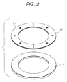
- the vibration actuator is constituted by an elastic member 11, two piezoelectric elements (electro-mechanical converting elements) 21 and 22 joined to the upper surface of the elastic member 11, four driving force output members 31 to 34 formed on the lower surface of the elastic member 11, and the like.
- the elastic member 11 is a disk-like elastic member with a central hole or a ring-shaped elastic member, and consists of a metal, plastic, or the like.
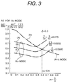
- the elastic member 11 can match an extensional vibration ((R-1) mode: an extensional vibration in a planar direction) with a 2nd-order bending vibration (B21 mode) by setting the dimensions of its ring shape.
- this matching is realized by adjusting the diameter of the inner hole of the ring shape.
- a curve (D) in Fig. 3 represents the (R-1) mode
- curves (A), (B), and (C) represent the cases of the B21 mode in correspondence with values 3/40, 2.5/40, and 2/40 of h (the thickness of the ring)/2a.
- each of the piezoelectric elements 21 and 22 has a half ring shape, and consists of, e.g., PZT.
- the piezoelectric elements 21 and 22 are polarized, as shown in Figs. 1A and 1C, and are applied with two-phase input voltages A and B.
- the driving force output members 31 to 34 are portions for picking up an elliptic motion generated by a synthesized vibration of the bending and extensional vibrations of the elastic member 1, and move relative to a fixed member 51 (relative moving member) while contacting it. As shown in Fig. 1A, the driving force output members 31 to 34 are arranged at 90° angular intervals on four outer edge positions of the lower surface of the elastic member 11. Spheres consisting of, e.g., silicon nitride are attached to the driving force output members 31 to 34 to improve their wear resistance.
- each driving force output member 31 to 34 are preferably arranged at positions other than the node positions of a longitudinal vibration so as to efficiently pickup a driving force.
- each driving force output member is preferably present at an antinode position of a vertical vibration in a direction substantially perpendicular to the moving plane.
- the vibration actuator generates a composite vibration of the bending and extensional vibrations by applying high-frequency voltages A and B to the two piezoelectric elements 21 and 22, thereby generating elliptic motions at the distal ends of the driving force output members 31 and 32 so as to generate a driving force.
- G represents ground.
- the two piezoelectric elements 21 and 22 are polarized in the same direction, and the high-frequency voltages A and B have a time phase difference of ⁇ /2 therebetween. Note that the two piezoelectric elements 21 and 22 may be polarized in opposite directions (see Fig. 6).
- an oscillator 41 is used for oscillating a high-frequency signal.
- the output from the oscillator 41 is divided into two outputs, so that one output is converted into a signal having a time phase difference of ⁇ /2 by a phase shifter 42 and is then connected to an amplifier 43, and the other output is directly connected to an amplifier 44.
- the outputs from the amplifiers 43 and 44 are respectively connected to the piezoelectric elements 21 and 22 as the high-frequency voltages A and B.
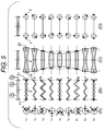
- Column (A) in Fig. 5 represents changes, over time, in two-phase high-frequency voltages A and B input to the vibration actuator at times t1 to t9.
- the abscissa represents the effective value of the high-frequency voltage.
- Column (B) in Fig. 5 shows the deformation states of the section of the vibration actuator, i.e., shows a change, over time (t1 to t9), in bending vibration generated in the vibration actuator.
- Column (C) in Fig. 5 shows the deformation states of the section of the vibration actuator, i.e., shows a change, over time (t1 to t9), in extensional vibration generated in the vibration actuator.
- Column (D) in Fig. 5 shows a change, over time (t1 to t9), in elliptic motion generated in the driving force output members 31 and 32 of the vibration actuator.
- the high-frequency voltage A generates a positive voltage
- the high-frequency voltage B similarly generates a positive voltage having the same magnitude as that generated by the voltage A.
- extensional vibrations by the high-frequency voltages A and B are generated in the extending direction.
- Mass points Y2 and Z2 exhibit maximum extension amounts to have a node X as the center, as indicated by arrows.
- the two vibrations are synthesized, the synthesis of the motions of the mass points Y1 and Y2 generates the motion of a mass point Y, and the synthesis of the motions of the mass points Z1 and Z2 generates the motion of a mass point Z.
- the high-frequency voltage B becomes zero, and the high-frequency voltage A generates a positive voltage.
- a bending vibration by the high-frequency voltage A is generated, the mass point Y1 moves in the negative direction, and the mass point Z1 in the positive direction.
- an extensional vibration by the high-frequency voltage A is generated, and the mass points Y2 and Z2 contract as compared to their amplitudes at time t1.
- the two vibrations are synthesized, and the mass points Y and Z move counterclockwise from their positions at time t1.
- the high-frequency voltage A generates a positive voltage
- the high-frequency voltage B similarly generates a negative voltage having the same magnitude as that generated by the voltage A.
- the bending motions by the high-frequency voltages A and B are synthesized and amplified, and the movement of the mass point Y1 is amplified in the negative direction as compared to its amplitude at time t2 and exhibits a maximum negative amplitude value.
- the movement of the mass point Z1 is amplified in the positive direction as compared to its amplitude at time t2 and exhibits a maximum positive amplitude value.
- C positive amplitude
- the high-frequency voltage A generates a negative voltage
- the high-frequency voltage B similarly generates a negative voltage having the same magnitude as that generated by the voltage A.
- extensional vibrations by the high-frequency voltages A and B are generated in the contracting direction.
- the mass points Y2 and Z2 exhibit maximum contraction amounts to have the node X as the center, as indicated by arrows.
- the two vibrations are synthesized, and the mass points Y and Z move counterclockwise from their positions at time t4.
- the vibration actuator generates elliptic motions at the distal ends of the driving force output members 31 and 32, thereby generating a driving force. Therefore, when the distal ends of the driving force output members 31 and 32 are brought into press contact with the fixed member 51, the elastic member 11 moves by itself relative to the fixed member 51.
- Fig. 6 shows a modification of the piezoelectric elements of the vibration actuator according to the first embodiment.
- the piezoelectric elements 21 and 22 are polarized in the same direction (upward direction), as shown in Fig. 2.
- the piezoelectric elements are polarized in different directions, i.e., the piezoelectric element 21 is polarized in the upward direction, and a piezoelectric element 22-1 is polarized in a downward direction.
- the piezoelectric element 22-1 shown in Fig. 6 can be applied with a driving signal whose sign is inverted from that to be applied to the piezoelectric element 22 shown in Fig. 2.
- Figs. 7A to 9 show the second embodiment of a vibration actuator according to the present invention.
- a piezoelectric element 20 is obtained by separately adhering two electrode plates 20a and 20b to a single piezoelectric material. With this arrangement, two piezoelectric elements need not be aligned, thus allowing easy manufacture. More specifically, since adhesion and alignment of the piezoelectric element are easy, adhesion precision between the elastic member 11 and the piezoelectric element 20 can be improved, and excitation nonuniformity caused by a deviation of the adhered position of the piezoelectric element can be eliminated. In addition, any right/left difference (the difference between moving speeds in +x- and -x-directions) depending on the moving directions can also be eliminated.
- portions, corresponding to the two electrode plates 20a and 20b, of the piezoelectric material are polarized in different directions.
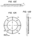
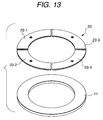
- Figs. 10A to 13 show the third embodiment of a vibration actuator according to the present invention.
- the first and second embodiments have exemplified a structure that allows only a one-dimensional movement (in the X-direction). However, the third embodiment allows a two-dimensional movement (in the X- and Y-directions).
- a piezoelectric material of a piezoelectric element 23 is polarized in one direction (see Fig. 10B), and the element 23 is divided into four electrode plates 23a, 23b, 23c, and 23d, as shown in Figs. 11 and 12A.
- a high-frequency signal from the oscillator 41 is divided into two outputs, so that one output is temporally phase-shifted by ⁇ /2 by phase shifters 42X and 42Y for the X- and Y-directions, and the outputs from the phase shifters are connected to amplifiers 43X and 43Y for the X- and Y-directions.
- the other output is directly connected to amplifiers 44X and 44Y for the X- and Y-directions.
- the amplifiers 43X, 43Y, 44X, and 44Y are connected to the electrode plates 23a, 23b, 23c, and 23d of the piezoelectric element via a selection switch 45.
- the selection switch 45 when all the contacts are connected to the X side (a broken line state in Fig. 10A), the output from the amplifier 43X is connected to the electrode plates 23a and 23b, and the output from the amplifier 44X is connected to the electrode plates 23c and 23d. Therefore, since the left electrode plates 23a and 23b are grouped, and the right electrode plates 23c and 23d are grouped, the same state as in Fig. 7A is attained, and a movement in the X-direction is allowed.
- the selection switch 45 when all the contacts are connected to the Y side (a solid line state in Fig. 10A), the output from the amplifier 43Y is connected to the electrode plates 23a and 23c, and the output from the amplifier 44Y is connected to the electrode plates 23b and 23d. Therefore, since the upper electrode plates 23a and 23c are grouped and the lower electrode plates 23b and 23d are grouped, a state obtained by rotating the state in Fig. 7A through 90° is attained, and a movement in the Y-direction is allowed.
- each of the driving force output members 31 to 34 is preferably defined by a portion of a solid bounded by a curved surface such as a sphere, ellipsoid, or the like so that uniform driving forces can be obtained in two directions, i.e., the X- and Y-directions.
- the piezoelectric element 23 is divided into four piezoelectric elements 23-1, 23-2, 23-3, and 23-4.
- Figs. 14 to 17D show the fourth embodiment of a vibration actuator according to the present invention.
- the switching operation for grouping the four-divided piezoelectric element portions in the X- and Y-directions is performed.
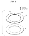
- piezoelectric elements for the X- and Y-directions are separately arranged on the two surfaces of the elastic member 11.
- piezoelectric elements 24-1 and 24-2 for the X-direction are arranged on the upper surface of the elastic member 11, and piezoelectric elements 25-1 and 25-2 for the Y-direction are arranged on the lower surface of the elastic member 11.
- a high-frequency signal from the oscillator 41 is connected to a driving circuit (a phase shifter 42X and amplifiers 43X and 44X) for the X-direction, and a driving circuit (a phase shifter 42Y and amplifiers 43Y and 44Y) for the Y-direction via a selection switch 46.
- the amplifiers 43X, 43Y, 44X, and 44Y are respectively connected to the piezoelectric elements 24-1, 24-2, 25-1, and 25-2 via the selection switch 46.
- the output from the amplifier 43X is connected to the piezoelectric element 24-1, and the output from the amplifier 44X is connected to the piezoelectric element 24-2, thus allowing a movement in the X-direction.
- the selection switch 46 when the moving contact is connected to the Y side (a solid line state in Fig. 14), the output from the amplifier 43Y is connected to the piezoelectric element 25-1, and the output from the amplifier 44Y is connected to the piezoelectric element 25-2, thus allowing a movement in the Y-direction.
- the driving force output member 32 is disposed at a position extending over the two piezoelectric elements 25-1 and 25-2. For this reason, as shown in Figs. 16A and 16B, the driving force output member 32 is attached via an attachment member 35 consisting of an insulating material such as fine ceramics.
- the radius of each of the piezoelectric elements 24 and 25 may be decreased by the width of each attachment member 35, or as shown in Fig. 17C, the interval between the piezoelectric elements 25-1 and 25-2 may be set to be larger than the size of the driving force output member 32, and the member 32 may be directly attached to the elastic member 11.
- attachment members 36 may extend outwardly from the elastic member 11, and the driving force output members 31 to 34 may be attached to these attachment members 36.
- the fourth embodiment uses a plurality of piezoelectric elements, if elements having equal polarization (poling) states selected, a piezoelectric element group suffering less nonuniformity in units of sectors as a whole can be obtained. Note that the same applies to the piezoelectric elements shown in Fig. 6 in the first embodiment or shown in Fig. 13 in the third embodiment.
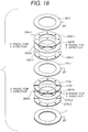
- Figs. 18 and 19 show the fifth embodiment of a vibration actuator according to the present invention.
- the piezoelectric elements for the X- and Y-directions are independently arranged on the two surfaces of the elastic member 11.
- piezoelectric elements for the X- and Y-directions are stacked on the upper surface of the elastic member 11.
- a piezoelectric element 27 for the Y-direction is joined to the upper surface of the elastic member 11, and is constituted by stacking piezoelectric materials 27A-1 and 27B-1, and 27A-2 and 27B-2 while sandwiching electrode plates 28YA and 28YB (e.g., copper plates) therebetween.
- electrode plates 28YA and 28YB e.g., copper plates
- a piezoelectric element 26 for the X-direction is joined to the piezoelectric element 27 for the Y-direction via an electrode plate 28-1, and is constituted by stacking piezoelectric materials 26A-1 and 26B-1, and 26A-2 and 26B-2 while sandwiching electrode plates 28XA and 28XB therebetween. Furthermore, an electrode plate 28-2 is joined to the upper surface of the element 26.
- the poling directions of the respective piezoelectric materials are as shown in Fig. 19.
- the electrode plates 28XA and 28XB, and the electrode plates 28YA and 28YB are respectively connected to inputs for the X- and Y-directions, and the electrode plates 28-1 and 28-2 and the elastic member 11 are connected to ground.
- Figs. 20A to 20C show the overall arrangement of the sixth embodiment of a vibration actuator according to the present invention.
- the sixth embodiment has substantially the same arrangement as that of the second embodiment shown in Figs. 7A to 7C, except that this embodiment exemplifies a case of an (R-1)-B11 mode (1st-order bending) in place of the (R-1)-B21 mode exemplified in the second embodiment. Nodes 11b of this (R-1)-B11 mode are shown in Fig. 20A.
- Figs. 21A and 21B show the overall arrangement of the seventh embodiment of a vibration actuator according to the present invention.
- the seventh embodiment has substantially the same arrangement as that of the third embodiment shown in Figs. 10A and 10B, except that this embodiment exemplifies a case of an (R-1)-B 11x -B 11Y mode (1st-order bending) in place of the (R-1)-B 21X -B 21Y mode exemplified in the third embodiment. Nodes 11b at this time are shown in Fig. 21A.
- the inner diameter of the ring-shaped elastic member decreases, and its thickness increases upon degeneracy of the vibrations of the (R-1) and B11 modes as compared to the (R-1)-B21 mode and (R-1)-B 21X -B 21Y mode. Therefore, these embodiments are suitable for a case wherein the inner diameter is to be increased with respect to the outer diameter due to a limitation on assembling dimensions in an object to be driven, i.e., a largest possible hole diameter is to be assured.
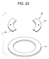
- Figs. 22A to 25 show the eighth embodiment of a vibration actuator according to the present invention. Note that Fig. 24A shows only the left half portion of an elastic member, but the right half portion is omitted, for the sake of simplicity.
- a vibration actuator 60 of the eighth embodiment is constituted by an elastic member 61, two piezoelectric elements 62 and 63 as electro-mechanical converting elements, which are, for example, adhered to the upper surface of the elastic member 61, and four driving force output members 64 to 67 projecting from the lower surface of the elastic member 61.
- the elastic member 61 is a ring-shaped elastic member, and consists of an elastic material such as a metal, plastic, or the like.
- a non-axisymmetric vibration [((1,1))-((1,1))' mode: planar vibration] can be matched with a 2nd-order bending vibration (B12 mode).
- This embodiment exemplifies degeneracy between the ((1,1))-((1,1))' mode and the B12 mode, and nodes 61a of a bending vibration of the B12 mode are indicated by broken lines in Figs. 22A and 24A.
- each of the piezoelectric elements 62 and 63 has a quarter ring shape in this embodiment, and consists of, e.g., PZT.
- the piezoelectric elements 62 and 63 are polarized, as shown in Fig. 22A, and are respectively applied with 2-phase input voltages A and B.
- the driving force output members 64 to 67 pick up an elliptic motion generated by a synthesized vibration of the bending and extensional vibrations of the elastic member 61, and move relative to a fixed member 68 (relative moving member) while contacting it. As shown in Fig. 22A, the driving force output members 64 to 67 are arranged at 90° angular intervals on four outer edge positions of the lower surface of the elastic member 61. Spheres consisting of, e.g., silicon nitride are attached to the driving force output members 64 to 67 to improve their wear resistance.
- the piezoelectric elements 62 and 63 may be arranged on the same surface as the driving force output members 64 to 67. In this case (also when the driving force output members 64 to 67 have a conductivity), in order to prevent short-circuiting, the members 64 to 67 are preferably joined to the surfaces of the piezoelectric elements 62 and 63 via insulating members.
- each driving force output member 64 to 67 are preferably arranged at positions other than the node positions of a bending vibration so as to efficiently pickup a driving force.
- each driving force output member is preferably arranged at an antinode position of a vertical vibration in a direction substantially perpendicular to the moving plane.
- the vibration actuator 60 generates a composite vibration of the non-axisymmetric and bending vibrations by applying high-frequency voltages A and B to the two piezoelectric elements 62 and 63, thereby generating elliptic motions at the distal ends of the driving force output members 64 and 65 so as to generate a driving force.
- G represents ground.
- the two piezoelectric elements 62 and 63 are polarized in the same direction, and the high-frequency voltages A and B have a time phase difference of ⁇ /2 therebetween. Note that the two piezoelectric elements 62 and 63 may be polarized in opposite directions.
- an oscillator 71 is used for oscillating a high-frequency signal.
- the output from the oscillator 71 is divided into two outputs, so that one output is converted into a signal having a time phase difference of ⁇ /2 by a phase shifter 72 and is then connected to an amplifier 73, and the other output is directly connected to an amplifier 74.
- the outputs from the amplifiers 73 and 74 are respectively connected to the piezoelectric elements 62 and 63 as the high-frequency voltages A and B.
- Column (A) in Fig. 25 shows changes, over time, in two-phase high-frequency voltages A and B input to the vibration actuator 60 at times t1 to t9.
- the abscissa in column (A) in Fig. 25 represents the effective value of the high-frequency voltage.
- Column (B) in Fig. 25 shows the deformation states of the section of the vibration actuator, i.e., shows a change, over time, in bending vibration generated in the vibration actuator at times t1 to t9.
- Column (C) in Fig. 25 shows the deformation states of the section of the vibration actuator, i.e., shows a change, over time, in non-axisymmetric vibration generated in the vibration actuator at times t1 to t9.
- Column (D) in Fig. 25 shows a change, over time, in elliptic motion at mass points X, Y, and Z of the vibration actuator at times t1 to t9.
- the high-frequency voltage A generates a positive voltage
- the high-frequency voltage B similarly generates a positive voltage having the same magnitude as that generated by the voltage A.
- bending vibrations by the high-frequency voltages A and B amplify one another
- mass points X1 and Z1 exhibit a maximum negative amplitude value
- a mass point Y1 exhibit a maximum positive amplitude value.
- the amplitudes of the non-axisymmetric vibrations by the high-frequency voltages A and B are zero
- the amplitudes of mass points X2, Y2, and Z2 are zero.
- the two amplitudes are synthesized, i.e., the synthesis of the motions of the mass points X1 and X2 generates a motion of a mass point X, the synthesis of the motions of the mass points Y1 and Y2 generates a motion of a mass point Y, and the synthesis of the motions of the mass points Z1 and Z2 generates a motion of a mass point Z.
- the high-frequency voltage A generates a positive voltage
- the high-frequency voltage B similarly generates a negative voltage having the same magnitude as that generated by the voltage A.
- the mass points X2 and Z2 are further displaced to the right in Fig. 25 by a maximum amount, and the mass point Y2 is further displaced to the left in Fig. 25 by a maximum amount.
- the two vibrations are synthesized, and the mass points X, Y, and Z further move counterclockwise from their positions at time t2.
- the high-frequency voltage A generates a negative voltage
- the high-frequency voltage B similarly generates a negative voltage having the same magnitude as that generated by the voltage A.
- bending motions by the high-frequency voltages A and B amplify each other, and the mass points X1, Y1, and Z1 have maximum amplitudes.
- the amplitudes of the non-axisymmetric motions by the high-frequency voltages A and B further decrease, and the displacement amounts of the mass points X2, Y2, and Z2 become zero.
- the two vibrations are synthesized, and the mass points X, Y, and Z further move counterclockwise from their positions at time t4.
- the vibration actuator generates elliptic motions shown in column (D) in Fig. 25 at the distal ends of the driving force output members 64 to 67, thereby generating a driving force. Therefore, when the distal ends of the driving force output members 64 to 67 are brought into press contact with the fixed member 68 as the relative moving member, the elastic member 61 moves by itself relative to the fixed member 68.
- the vibration actuator 60 which can one-dimensionally move in a plane, and can be easily assembled in a cylindrical portion such as a lens barrel can be provided.
- the vibration actuator 60 since the elastic member 61 used in the vibration actuator 60 according to the present invention has a ring shape, the vibration actuator can be applied to, e.g., a lens barrel of a camera, and can be used as a driving source for a blur prevention device.
- Figs. 26A to 28 show the ninth embodiment of a vibration actuator according to the present invention.
- the eighth embodiment provides a structure that allows only a one-dimensional movement ( ⁇ x-directions). However, this embodiment allows independent two-dimensional movements ( ⁇ x-directions and ⁇ y-directions).
- a vibration actuator 60-1 of this embodiment comprises a ring-shaped elastic member 61-1, four quarter ring-shaped piezoelectric elements 62a, 63a, 62b, and 63b which are arranged at equal angular intervals on the upper surface of the elastic member 61-1, and four driving force pickup portions 64 to 67 which are arranged at equal angular intervals on the upper surface of the elastic member 61-1.
- all the piezoelectric elements 62a, 63a, 62b, and 63b are adhered on a single surface.
- the piezoelectric elements 62a and 63a, and the piezoelectric elements 62b and 63b may be respectively adhered on the two surfaces of the elastic member.
- a high-frequency signal from an oscillator 71 is divided into two outputs.
- One output is temporally phase-shifted by ⁇ /2 by phase shifters 72X and 72Y for the X- and Y-directions, and the outputs from the phase shifters are connected to amplifiers 73X and 73Y for the X- and Y-directions.
- the other output is directly connected to amplifiers 74X and 74Y for the X- and Y-directions.
- the amplifiers 73X, 73Y, 74X, and 74Y are respectively connected to the piezoelectric elements 62a, 62b, 63a, and 63b via a selection switch 75.
- the selection switch 75 when all the contacts are connected to the X side, the output from the amplifier 73X is connected to the piezoelectric element 62a, and the output from the amplifier 74X is connected to the piezoelectric element 63a. Therefore, since the piezoelectric elements 62a and 63a which oppose in the X-direction are grouped, the same state as in Fig. 22A is attained, and the vibration actuator 60-1 can move in the ⁇ X-directions.
- the output from the amplifier 73Y is connected to the piezoelectric element 62b, and the output from the amplifier 74Y is connected to the piezoelectric element 63b. Therefore, since the piezoelectric elements 62b and 63b which oppose in the Y-direction are grouped, a state obtained by rotating the state in Fig. 22A through 90° is attained, and the vibration actuator 60-1 can move in the ⁇ Y-directions.
- each of the driving force output members 64 to 67 is preferably defined by a portion of a solid bounded by a curved surface such as a sphere, ellipsoid, or the like, so that uniform driving forces can be obtained in two directions, i.e., the X- and Y-directions.
- a ring-shaped piezoelectric element is adhered to an elastic member, and four electrodes are further adhered to the piezoelectric element at equal angular intervals in place of adhering the four quarter ring-shaped piezoelectric elements 62a, 63a, 62b, and 63b to the elastic member 61-1 like in the ninth embodiment.
- Fig. 29 shows an elastic member and a piezoelectric element in this embodiment.
- a ring-shaped piezoelectric element 69 is adhered on the upper surface of a ring-shaped elastic member 61-2, and a silver electrode is printed on almost the entire region of the upper surface of the piezoelectric element 69. Portions of the silver electrode are cut away to form quarter-circular electrodes 62c, 63c, 62d, and 63d. Note that in place of cutting away unnecessary portions of the printed silver electrode, unnecessary portions may be masked in advance, and a silver electrode may be formed using a thin-film formation technique such as deposition to obtain four electrodes.
- the electro-mechanical converting element comprises a piezoelectric element.
- the electro-mechanical converting element may comprise an electrostrictive element, magnetostrictive element, or the like.
- Each of the above embodiment may be suitably applied to an X-Y stage for a microscope, a feeder of plotter sheets, and the like in addition to driving a blur correction lens in two directions.
Landscapes
- General Electrical Machinery Utilizing Piezoelectricity, Electrostriction Or Magnetostriction (AREA)
Applications Claiming Priority (4)
| Application Number | Priority Date | Filing Date | Title |
|---|---|---|---|
| JP6318150A JPH08182351A (ja) | 1994-12-21 | 1994-12-21 | 超音波アクチュエータ |
| JP318150/94 | 1994-12-21 | ||
| JP7134895A JPH08331874A (ja) | 1995-06-01 | 1995-06-01 | 超音波アクチュエータ |
| JP134895/95 | 1995-06-01 |
Publications (2)
| Publication Number | Publication Date |
|---|---|
| EP0718899A2 true EP0718899A2 (fr) | 1996-06-26 |
| EP0718899A3 EP0718899A3 (fr) | 1997-12-29 |
Family
ID=26468885
Family Applications (1)
| Application Number | Title | Priority Date | Filing Date |
|---|---|---|---|
| EP95309345A Withdrawn EP0718899A3 (fr) | 1994-12-21 | 1995-12-21 | Organe d'entraínement par des vibrations |
Country Status (2)
| Country | Link |
|---|---|
| US (1) | US6072266A (fr) |
| EP (1) | EP0718899A3 (fr) |
Cited By (2)
| Publication number | Priority date | Publication date | Assignee | Title |
|---|---|---|---|---|
| US5872417A (en) * | 1995-12-04 | 1999-02-16 | Nikon Corporation | Multiple degrees of freedom vibration actuator |
| WO2000030186A1 (fr) * | 1998-11-16 | 2000-05-25 | Brian Andersen | Organe de commande de vibration |
Families Citing this family (8)
| Publication number | Priority date | Publication date | Assignee | Title |
|---|---|---|---|---|
| JP3190634B2 (ja) * | 1999-01-05 | 2001-07-23 | セイコーインスツルメンツ株式会社 | 圧電アクチュエータおよび圧電アクチュエータの駆動方法並びに圧電アクチュエータの駆動方法をコンピュータに実行させるプログラムを格納した、コンピュータが読取可能な記憶媒体 |
| AU2002258356A1 (en) | 2000-11-03 | 2002-09-12 | Herzel Laor | Piezoelectric optical cross connect switching |
| WO2005101647A2 (fr) * | 2003-09-30 | 2005-10-27 | The Trustees Of Columbia University In The City Of New York | Propulsion harmonique et organe de commande harmonique |
| JP4827441B2 (ja) * | 2005-06-01 | 2011-11-30 | キヤノン株式会社 | 振動波アクチュエータ |
| JP2007221924A (ja) * | 2006-02-17 | 2007-08-30 | Seiko Epson Corp | 圧電アクチュエータ、圧電アクチュエータの駆動制御方法、および電子機器 |
| JP2007274865A (ja) * | 2006-03-31 | 2007-10-18 | Casio Comput Co Ltd | 圧電アクチュエータ、これを用いた搬送装置及び手ぶれ補正装置 |
| WO2008096797A1 (fr) * | 2007-02-06 | 2008-08-14 | Sharp Kabushiki Kaisha | Dispositif d'entraînement, dispositif d'imagerie avec le dispositif d'entraînement, et matériel d'imagerie |
| DE102009049719A1 (de) * | 2009-10-17 | 2011-04-21 | Physik Instrumente (Pi) Gmbh & Co. Kg | Aktuator |
Citations (2)
| Publication number | Priority date | Publication date | Assignee | Title |
|---|---|---|---|---|
| EP0536832A1 (fr) * | 1991-10-05 | 1993-04-14 | Philips Patentverwaltung GmbH | Moteur électrique rotatif ou linéaire à organe d'actionnement commandé par des vibrations ultrasonores |
| US5323082A (en) * | 1989-05-03 | 1994-06-21 | Spectra Physics Lasers, Inc. | Piezoelectric actuator for planar alignment |
Family Cites Families (14)
| Publication number | Priority date | Publication date | Assignee | Title |
|---|---|---|---|---|
| JPS6013481A (ja) * | 1983-07-04 | 1985-01-23 | Canon Inc | 振動波モ−タ |
| US4562373A (en) * | 1983-10-21 | 1985-12-31 | Matsushita Electric Industrial Co., Ltd. | Piezoelectric motor |
| JPS60170472A (ja) * | 1984-02-10 | 1985-09-03 | Canon Inc | 振動波モ−タ |
| JPS60210172A (ja) * | 1984-04-02 | 1985-10-22 | Canon Inc | 振動波モ−タ |
| US4831305A (en) * | 1984-04-02 | 1989-05-16 | Canon Kabushiki Kaisha | Vibration wave motor |
| JPS61224878A (ja) * | 1985-03-29 | 1986-10-06 | Canon Inc | 振動波モ−タ− |
| EP0258449B1 (fr) * | 1986-02-18 | 1992-10-21 | Matsushita Electric Industrial Co., Ltd. | Moteur ultrasonique |
| JPH06106028B2 (ja) * | 1987-02-02 | 1994-12-21 | リオン株式会社 | 圧電共振モ−タ |
| JPH0217877A (ja) * | 1988-07-05 | 1990-01-22 | Brother Ind Ltd | 振動子及び該振動子を用いた超音波モータ |
| US5105117A (en) * | 1989-10-31 | 1992-04-14 | Brother Kogyo Kabushiki Kaisha | Ultrasonic motor |
| US5073739A (en) * | 1990-02-27 | 1991-12-17 | Nisca Corporation | Vibration-coupling type ultrasonic actuator and method for operating the same |
| JP3118251B2 (ja) * | 1990-11-21 | 2000-12-18 | ニスカ株式会社 | 超音波駆動装置及びその方法 |
| US5416375A (en) * | 1992-06-15 | 1995-05-16 | Olympus Optical Co., Ltd. | Ultrasonic motor |
| IL106296A0 (en) * | 1993-07-09 | 1993-12-28 | Nanomotion Ltd | Ceramic motor |
-
1995
- 1995-12-19 US US08/574,928 patent/US6072266A/en not_active Expired - Lifetime
- 1995-12-21 EP EP95309345A patent/EP0718899A3/fr not_active Withdrawn
Patent Citations (2)
| Publication number | Priority date | Publication date | Assignee | Title |
|---|---|---|---|---|
| US5323082A (en) * | 1989-05-03 | 1994-06-21 | Spectra Physics Lasers, Inc. | Piezoelectric actuator for planar alignment |
| EP0536832A1 (fr) * | 1991-10-05 | 1993-04-14 | Philips Patentverwaltung GmbH | Moteur électrique rotatif ou linéaire à organe d'actionnement commandé par des vibrations ultrasonores |
Cited By (2)
| Publication number | Priority date | Publication date | Assignee | Title |
|---|---|---|---|---|
| US5872417A (en) * | 1995-12-04 | 1999-02-16 | Nikon Corporation | Multiple degrees of freedom vibration actuator |
| WO2000030186A1 (fr) * | 1998-11-16 | 2000-05-25 | Brian Andersen | Organe de commande de vibration |
Also Published As
| Publication number | Publication date |
|---|---|
| US6072266A (en) | 2000-06-06 |
| EP0718899A3 (fr) | 1997-12-29 |
Similar Documents
| Publication | Publication Date | Title |
|---|---|---|
| US5039899A (en) | Piezoelectric transducer | |
| US6252332B1 (en) | Ultrasonic motor | |
| US5872417A (en) | Multiple degrees of freedom vibration actuator | |
| US6707232B2 (en) | Piezoelectric driving body, ultrasonic motor and electronic apparatus having an ultrasonic motor | |
| US5760528A (en) | Vibration actuator | |
| US7005776B1 (en) | Ultrasonic motor and electronic apparatus equipped with ultrasonic motor | |
| US5585685A (en) | Vibration driven apparatus | |
| US6072266A (en) | Vibration actuator | |
| EP0691692B1 (fr) | Moteur entraíné par des vibrations | |
| US5831370A (en) | Vibration actuator | |
| JP5029948B2 (ja) | 超音波モータ | |
| JPS62259485A (ja) | 圧電駆動装置 | |
| JPH08182351A (ja) | 超音波アクチュエータ | |
| JPH0965674A (ja) | 振動アクチュエータ | |
| JP3200315B2 (ja) | 振動アクチュエータ | |
| JP2971971B2 (ja) | 超音波アクチュエータ | |
| JPH11235063A (ja) | 超音波モータを利用したステージ、および、これを用いた電子機器、印刷装置 | |
| JP3448783B2 (ja) | 超音波モータ | |
| JPH0993962A (ja) | 振動アクチュエータ | |
| JPH05115846A (ja) | 超音波振動子およびこの振動子を有する駆動装置 | |
| JP3492163B2 (ja) | 圧電アクチュエータ | |
| JP2538033B2 (ja) | 平面型超音波アクチュエ―タ | |
| JPH07110143B2 (ja) | 平面型超音波アクチュエータ | |
| JPS63214381A (ja) | 超音波振動子とその駆動制御方法 | |
| JPH08331874A (ja) | 超音波アクチュエータ |
Legal Events
| Date | Code | Title | Description |
|---|---|---|---|
| PUAI | Public reference made under article 153(3) epc to a published international application that has entered the european phase |
Free format text: ORIGINAL CODE: 0009012 |
|
| AK | Designated contracting states |
Kind code of ref document: A2 Designated state(s): DE FR GB |
|
| PUAL | Search report despatched |
Free format text: ORIGINAL CODE: 0009013 |
|
| AK | Designated contracting states |
Kind code of ref document: A3 Designated state(s): DE FR GB |
|
| 17P | Request for examination filed |
Effective date: 19980520 |
|
| 17Q | First examination report despatched |
Effective date: 19991216 |
|
| STAA | Information on the status of an ep patent application or granted ep patent |
Free format text: STATUS: THE APPLICATION IS DEEMED TO BE WITHDRAWN |
|
| 18D | Application deemed to be withdrawn |
Effective date: 20000427 |