EP0258449B1 - Moteur ultrasonique - Google Patents
Moteur ultrasonique Download PDFInfo
- Publication number
- EP0258449B1 EP0258449B1 EP87901637A EP87901637A EP0258449B1 EP 0258449 B1 EP0258449 B1 EP 0258449B1 EP 87901637 A EP87901637 A EP 87901637A EP 87901637 A EP87901637 A EP 87901637A EP 0258449 B1 EP0258449 B1 EP 0258449B1
- Authority
- EP
- European Patent Office
- Prior art keywords
- ultrasonic motor
- electrode
- electrode groups
- vibrating stator
- vibration
- Prior art date
- Legal status (The legal status is an assumption and is not a legal conclusion. Google has not performed a legal analysis and makes no representation as to the accuracy of the status listed.)
- Expired - Lifetime
Links
- 239000000126 substance Substances 0.000 abstract 3
- 230000000750 progressive effect Effects 0.000 abstract 1
- 230000007935 neutral effect Effects 0.000 description 10
- 238000006073 displacement reaction Methods 0.000 description 7
- 230000010287 polarization Effects 0.000 description 5
- 239000000463 material Substances 0.000 description 4
- XEEYBQQBJWHFJM-UHFFFAOYSA-N Iron Chemical compound [Fe] XEEYBQQBJWHFJM-UHFFFAOYSA-N 0.000 description 2
- 230000005284 excitation Effects 0.000 description 2
- 239000004411 aluminium Substances 0.000 description 1
- XAGFODPZIPBFFR-UHFFFAOYSA-N aluminium Chemical compound [Al] XAGFODPZIPBFFR-UHFFFAOYSA-N 0.000 description 1
- 229910052782 aluminium Inorganic materials 0.000 description 1
- 230000033228 biological regulation Effects 0.000 description 1
- 239000000919 ceramic Substances 0.000 description 1
- 238000010276 construction Methods 0.000 description 1
- 230000001419 dependent effect Effects 0.000 description 1
- 229910052742 iron Inorganic materials 0.000 description 1
Images


Classifications
-
- H—ELECTRICITY
- H02—GENERATION; CONVERSION OR DISTRIBUTION OF ELECTRIC POWER
- H02N—ELECTRIC MACHINES NOT OTHERWISE PROVIDED FOR
- H02N2/00—Electric machines in general using piezoelectric effect, electrostriction or magnetostriction
- H02N2/10—Electric machines in general using piezoelectric effect, electrostriction or magnetostriction producing rotary motion, e.g. rotary motors
- H02N2/16—Electric machines in general using piezoelectric effect, electrostriction or magnetostriction producing rotary motion, e.g. rotary motors using travelling waves, i.e. Rayleigh surface waves
- H02N2/166—Motors with disc stator
Definitions
- the present invention relates to an ultrasonic motor wherein the driving force is given by an elastic travelling wave excited by a piezoelectric element.
- An ultrasonic motor is constituted by a vibrating stator which comprises a piezoelectric element, and an elastic element and a rotor which is disposed to touch the vibrating stator with pressure.
- a vibrating stator which comprises a piezoelectric element
- an elastic element and a rotor which is disposed to touch the vibrating stator with pressure.
- US-A-4 562 374 discloses an ultrasonic motor having two driving electrodes with respective electrode groups comprising small electrodes having a circumferential length of one half wavelength. These electrodes are arranged in such a manner that a positional shift of one quarter of the wavelength to each other corresponding to a phase difference of 90° is provided. By applying voltages having phase differences of 90° from each other to the respective driving electrodes, an elastic travelling wave is generated.
- this ultrasonic motor comprise plural small electrodes of one quarter wavelength which are provided in such a manner that they are interdigitated with each other, plural of them being electrically connected with each other. Further embodiments of this ultrasonic motor are provided with driving electrodes comprising such plural electrodes each having a length of one half wavelength, which are formed in the respective piezoelectric members. The piezoelectric members are disposed with a positional shift of one quarter of the wavelength to each other. The elastic travelling wave is generated by applying voltages having a phase difference of 90° from each other with respect to the driving electrodes.
- the vibrating stator is ring-shaped or bar-shaped.
- the area of the piezoelectric element responding to one electrode-group is small, because the width in the radial direction is narrow and two electrode-groups are disposed to divide regions in the circumferential direction. Therefore, the driving force for exciting vibrations of one phase is not sufficient, and it is accordingly difficult to obtain a high driving efficiency.
- a vibrating stator for an ultrasonic motor is e.g. disclosed in Japanese Unexamined Published Application Sho 60-183982, which is constituted by bonding an elastic element and two slices of a piezoelectric element coaxially into three layers. These two slices of the piezoelectric element are disk-shaped. Voltage is individually applied to each of the piezoelectric elements and they are superimposed in such a manner that the phases of the excited vibration differ by 90°. Therefore, the area of the piezoelectric element which supplies the driving force for excitation is large, and its efficiency is high.
- the rotor is driven by these two vibration members at respective driving frequencies f, which may be the same or different. In the first case only one driving voltage source is needed.
- this ultrasonic motor comprises vibrating stators which are disposed in a concentric relation to each other. However, each of the vibrating stators is independent concerning the construction and it is individually able to excite the elastic travelling wave.
- the object underlying the present invention is to provide an ultrasonic motor which obtains a high efficiency by optimizing two sets of electrode-groups having different phases in position.
- the ultrasonic motor according to the invention comprises electrodes which are disposed in the form of two sets of concentric circles on the surface of the piezoelectric element, which constitutes one disk-shaped vibration body as a whole.
- flexural vibrations of high order are excited.
- These flexural vibrations are of the second order in the radial direction and of the third order in the circumferential direction with a nodal circle where the vibration displacement is zero.
- the signs of the electric charge are opposite inside and outside of the nodal circle. This polarity change of the electric charge is used according to the invention in order to improve the efficiency of vibration excitation.
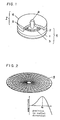
- FIG.1 is a partially cut-out perspective view of an embodiment of a disk type ultrasonic motor in accordance with the present invention
- FIG.2 is a perspective view for explaining the operation of the embodiment of FIG.1
- FIG.3(a), (b) and (c) are cross sectional views of the vibrating stator of the embodiment of FIG.1, a displacement distribution graph of the same and a plane view showing the constitution of the electrodes of the same, respectively
- FIG.4(a), (b) and (c) are cross sectional views of a vibrating stator of a disk type ultrasonic motor of another embodiment, a displacement distribution graph of the same and a plane view showing the constitution of the electrodes of the same, respectively
- FIG.5(a), (b) and (c) are cross sectional views of a vibrating stator of a disk type ultrasonic motor of another embodiment, a displacement distribution graph of the same and a plane view showing the constitution of the electrodes of the same, respectively
- FIG.6 is a cross sectional view showing the
- FIG.1 is a cut-out perspective view of a disk type ultrasonic motor.
- 1 is a piezoelectric element of a piezoelectric ceramic etc.
- 2 is an elastic element of an iron or aluminium etc.
- 3 are projections which are for taking mechanical outputs and are disposed on the surface of the elastic element 2.
- the piezoelectric element 1 and the elastic element 2 are bonded concentrically thereby to constitute the vibrating stator 4.
- 5 is an wear-resistive frictional material
- 6 is an elastic element
- the rotor 7 is constituted by bonding them together.
- the projections 3 which are disposed on the vibrating stator 4 and the rotor 7 are in pressure contact pressure with the frictional material 5 therebetween.
- FIG.2 is a figure of a vibration mode and an amplitude distribution in the radial direction of the above-mentioned vibrating stator 4.
- the vibration mode shown in the figure adopts a flexural vibration mode of the second order in the radial direction and of the third order in the circumferential direction. Since at least three vibrating loops are required for holding the rotor 7, the flexural vibration modes of the second order or higher in the radial direction and of the third order or higher in the circumferential direction are applicable similarly.
- r0 is the position which is a loop of the flexural vibration where the amplitude is maximum.
- the rotation speed of the rotor of the ultrasonic motor is proportional to the vibrating amplitude of the vibrating stator, the maximum rotation speed can be obtained by setting the rotor to touch the loop of vibrations. Therefore, the projections 3 are normally disposed in this position.
- FIG.3 shows the displacement distribution graph of the vibrating stator 4 and the constitution of the electrode of the piezoelectric element 1 for the disk type ultrasonic motor shown in FIG.1.
- the electrode-groups A 9 and B 10 are constituted concentrically within a nodal circle of flexural vibrations of the vibrating stator 4, and they consist of small electrode-groups, wherein the circumferential direction lengths correspond to half wavelengths of the elastic travelling wave, respectively.
- the electrode-groups A 9 and B 10 are disposed with a phase difference of 90° in the location in the circumferential direction.
- An electrode on the surface which is opposite to the surface shown in the figure is a flat electrode.
- the polarization directions of the small electrode parts which form the electrode groups A 9 and B 10 and are adjacent to each other are reversed in the thickness direction.
- the electrode groups A 9 and B 10 are short-circuited, respectively, and alternating voltages with different in phases by 90° are applied thereto, respectively, so that the flexural vibration which travels in the circumferential direction is excited.
- respective electrode areas are designed with respect to the widths in the radial direction so as to make induced electric charges in the electrode-groups A 9 and B 10 by the above-mentioned flexural vibration equal (i.e. by making mechanical impedances equal)
- a standing wave having the same amplitude can be excited by a driving voltage of the same amplitude, and the travelling wave can be excited efficiently by equation (1).
- FIG.4 shows the displacement distribution of a vibration stator 11 and the electrode configuration of a piezoelectric element 12 in another embodiment of an ultrasonic motor of the present invention.
- Electrode-group A1 13 is disposed outside a nodal circle of the flexural vibrations of the vibrating stator 4, and the electrode-group B1 14 is disposed inside the nodal circle.
- Each electrode is constituted concentrically, and comprises small electrodes, wherein the length in the circumferential direction corresponds to a half wavelength of the elastic travelling wave, respectively.
- the electrodes A1 13 and B1 14 are disposed with a phase difference of 90° in position in the circumferential direction.
- An electrode on the surface which is opposite to the surface shown in that figure is a flat electrode.
- the polarization directions of the small electrode parts which are adjacent to each other form the electrode-groups A1 13 and B1 14 are opposite with respect to the thickness direction.
- the electrode-groups A1 13 and B1 14 are short-circuited, respectively, and alternating voltages with a phase difference by 90° are applied thereto, respectively, so that the flexural vibration which travels in circumferential direction is excited.
- the respective electrode areas are designed so as to make the electric charges induced in the electrode groups A1 13 and B1 14 by the above-mentioned flexural vibration equal (i.e. by making mechanical impedances equal)
- an elastic travelling wave having the same amplitude can be excited by the same driving voltage, and the travelling wave can be excited efficiently as shown by equation (1).
- FIG.5 shows the displacement distribution of a vibrating element 15 and the electrode configuration of a piezoelectric element 16 in a further embodiment of an ultrasonic motor of the present invention.
- Electrode group A2 17 is disposed outside a nodal circle of flexural vibration of the vibrating stator 4, and electrode groups A3 18 and B2 19 are disposed inside the nodal circle.
- the three electrode-groups are constituted concentrically, and comprise small electrodes, wherein the length in the circumferential direction corresponds to a half wavelength of the elastic travelling wave.
- the electrode groups A2 17 and A3 18 are disposed with the same phase in position in the circumferential direction, and the electrode groups A3 18 and B2 19 are disposed with a phase difference of 90° in position in the circumferential direction.
- An electrode on the surface which is opposite to the surface shown in that figure is a flat electrode.
- the polarization directions of the small electrode parts adjacent each other and forming the electrode groups A2 17, A3 18 and B2 19 are opposite with respect to the thickness direction.
- the signs of the electric charges which are induced in the corresponding small electrodes in the electrode groups A2 17 and A3 18 are opposite to each other when the directions of polarization are the same, and therefore, the directions of polarization are made opposite as shown in that figure. Therefore, when used, the electrode groups A2 17, A3 18 and B2 19 are short-circuited, respectively, and alternating voltages with phase differences of 90° are applied thereto, respectively, so that the flexural vibration which travels in the circumferential direction is excited.
- the respective electrode areas are designed so as to make the sum of the electric charges in the electrode groups A2 17 and A3 18 and the electric charge in the electrode group B2 19 by the above-mentioned flexural vibration equal (i.e. by making mechanical impedances equal), a standing wave having the same amplitude can be excited by the driving voltage of the same amplitude, and the travelling wave can be efficiently excited as shown by the equation (1).
- the electrodes can be constituted on the whole disk surface of the vibrating stator, an ultrasonic motor capable of producing a large power is obtainable.
- the electrode groups A2 17 and A3 18 are used with the same phase
- the electrode groups A2 17 and B2 19 can be used similary with the same phase.
- the elastic travelling wave can further be excited efficiently by driving voltages which have the same amplitude and have a phase difference of 90°.
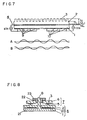
- FIG.6 is a cross sectional view of the vibrating stator 4 in the circumferential direction for explaining the use of the projections 3.
- NL is the neutral line of the flexural vibration of the vibrating stator 4
- h is the distance from the neutral line NL to a surface of the vibrating stator 4
- the speed of the rotor 7 is in proportion to the amplitude of the travelling wave of the flexural vibration and the distance h. Therefore, to make the speed of the rotor 7 high, the amplitude of the flexural vibration or the distance h should be made large.
- the distance h between the neutral line NL and the surface of the vibrating stator 4 should be made large.
- the projections 3 are provided; consequently, the distance h is enlarged to h1 without largely changing the neutral line NL.
- the speed of the rotor 7 increases h1/h times in comparison with the case having no projections 3.
- FIG.7 is a figure showing a simplified cross-sectional view of the projections and the vibrating stator for showing two sets of standing waves for explaining the positioning regulation and numeral restriction of the projections .
- the electrode groups A and B comprise a small electrode which corresponds to a half wavelength of the travelling wave, and they are short-circuited at the time of driving as shown in the figure, respectively, and they are driven by voltages having a phase difference of 90° of time (for example a sine wave and a cosine wave), respectively.
- the waves which are drawn below the vibrating stator 4 show standing waves of the flexural vibration excited by the electrode groups A and B.
- the thickness of the elastic element becomes equivalently thick, and thereby the flexural rigidity becomes large.
- the flexural vibration becomes difficult to be excited; therefore, to drive efficiently, there should be no projections 3 at the loops of both standing waves.
- the mechanical impedances seen from the two driving terminals can be made equal, so that the number of the projections within one wavelength becomes a multiple of four by the restrictions.
- NL of FIG.7 is a neutral line before providing of the projections 3
- h is the distance to the surface of the elastic element from a neutral line NL
- NL1 is the neutral line after providing the projections 3
- h1 is the distance to the surface of the elastic element from a neutral line NL1
- an increase of distance to the surface of the elastic element from the neutral line NL1 is larger than a change of position of the neutral line, so that an increase of the rotation speed is obtainable.
- FIG.8 is a cross-sectional view of an ultrasonic motor which shows an embodiment of a position-fixing of the vibrating stator.
- Projections 20 are disposed on a nodal of vibration of the vibrating stator 4, and the vibrating stator 4 is fixed on a fixed stand 21 via the projections 20.
- 22 is a leaf spring for putting the rotor 7 in pressure contact with the vibrating stator 4 , which is held by a hearing 23.
- the position-fixing of the vibrating stator 4 can also be made via an internal circumference of the vibrating stator 4 where the amplitude of vibration becomes small.
- an ultrasonic motor having high efficiency is obtainable, and a motor is very suitable for the requirements of compact size and high efficiency, for instance, for lens-driving of a video camera or driving motor of a printer etc., can be offered.
Landscapes
- General Electrical Machinery Utilizing Piezoelectricity, Electrostriction Or Magnetostriction (AREA)
Abstract
Claims (8)
- Moteur ultrasonique comprenant :- un stator vibrant (4) comportant un élément élastique (2) et un élément piézoélectrique (1 ; 12 ; 16) fixé à l'élément élastique ;- une multitude d'électrodes de commande (9, 10 ; 10, 14 ; 17, 18, 19) qui sont placées sur l'élément piézoélectrique (1 ; 12 ; 16), les électrodes de commande comprenant au moins deux groupes d'électrodes, et- un rotor (7) qui est en contact avec le stator vibrant,
caractérisé en ce que :- à la fois l'élément élastique (2) et l'élément piézoélectrique (1 ; 12 ; 16) sont en forme de disque et que les groupes d'électrodes sont disposés en alignement concentrique l'un avec l'autre d'une manière telle que les groupes d'électrodes sont disposés à l'extérieur et à l'intérieur d'un cercle des noeuds des vibrations de flexion produites dans le stator vibrant, et- chacun des groupes d'électrodes comprend de multiples petites électrodes, chacune ayant une longueur circonférentielle qui correspond à une demie longueur d'onde d'une onde progressive de la vibration de flexion. - Moteur ultrasonique selon la revendication 1, dans lequel les électrodes de commande (9, 10) comportent deux groupes d'électrodes disposés concentriquement l'un par rapport à l'autre à l'intérieur du cercle des noeuds.
- Moteur ultrasonique selon la revendication 1, dans lequel un premier groupe d'électrodes des électrodes de commande (14) est disposé à l'intérieur du cercle des noeuds et l'autre groupe d'électrodes des électrodes de commande (13) est disposé à l'extérieur du cercle des noeuds.
- Moteur ultrasonique selon la revendication 1, dans lequel les électrodes de commande comportent trois groupes d'électrodes, dont deux groupes (18, 19) sont disposés à l'intérieur du cercle des noeuds et dont le dernier (17) est disposé à l'intérieur du cercle des noeuds pour être connecté à un des deux autres groupes d'électrodes (18, 19).
- Moteur ultrasonique selon l'une quelconque des revendications 1 à 4, dans lequel le stator vibrant (4) est fixé en position par rapport au cercle des noeuds ou à une circonférence interne du stator vibrant.
- Moteur ultrasonique selon l'une quelconque des revendications 1 à 5, dans lequel le stator vibrant (4) comporte des saillies (3) qui établissent un contact avec le rotor (7) à un ventre de la vibration de flexion.
- Moteur ultrasonique selon la revendication 6, dans lequel la nombre de saillies (3) est un multiple d'un nombre entier de quatre d'une première longueur d'onde de l'onde progressive, et chacune des saillies (3) est disposée de manière telle à éviter une position où chacune des deux ondes stationnaires constituant l'onde progressive constitue un ventre.
- Moteur ultrasonique selon la revendication 6 ou 7, dans lequel la fréquence de résonance la plus basse des saillies (3) est supérieure à la fréquence de résonance de la vibration de flexion du stator vibrant (4).
Applications Claiming Priority (12)
| Application Number | Priority Date | Filing Date | Title |
|---|---|---|---|
| JP34624/86 | 1986-02-18 | ||
| JP61034624A JPS62193569A (ja) | 1986-02-18 | 1986-02-18 | 超音波モ−タ |
| JP61035962A JPS62196080A (ja) | 1986-02-20 | 1986-02-20 | 超音波モ−タ |
| JP61035959A JPH067751B2 (ja) | 1986-02-20 | 1986-02-20 | 超音波モ−タ |
| JP61035960A JPS62196078A (ja) | 1986-02-20 | 1986-02-20 | 超音波モ−タ |
| JP35963/86 | 1986-02-20 | ||
| JP61035954A JPH067750B2 (ja) | 1986-02-20 | 1986-02-20 | 超音波モ−タ |
| JP35959/86 | 1986-02-20 | ||
| JP35960/86 | 1986-02-20 | ||
| JP35954/86 | 1986-02-20 | ||
| JP61035963A JPS62196081A (ja) | 1986-02-20 | 1986-02-20 | 超音波モ−タ |
| JP35962/86 | 1986-02-20 |
Publications (3)
| Publication Number | Publication Date |
|---|---|
| EP0258449A1 EP0258449A1 (fr) | 1988-03-09 |
| EP0258449A4 EP0258449A4 (fr) | 1988-06-16 |
| EP0258449B1 true EP0258449B1 (fr) | 1992-10-21 |
Family
ID=27549731
Family Applications (1)
| Application Number | Title | Priority Date | Filing Date |
|---|---|---|---|
| EP87901637A Expired - Lifetime EP0258449B1 (fr) | 1986-02-18 | 1987-02-17 | Moteur ultrasonique |
Country Status (4)
| Country | Link |
|---|---|
| US (1) | US4829209A (fr) |
| EP (1) | EP0258449B1 (fr) |
| DE (1) | DE3782301T2 (fr) |
| WO (1) | WO1987005166A1 (fr) |
Families Citing this family (36)
| Publication number | Priority date | Publication date | Assignee | Title |
|---|---|---|---|---|
| CN1035213A (zh) * | 1987-12-29 | 1989-08-30 | 精工电子工业株式会社 | 行波电机 |
| JPH01232128A (ja) * | 1988-03-11 | 1989-09-18 | Kiyousan Denki Kk | エンジンのスロットル弁制御装置 |
| US5023853A (en) * | 1988-06-27 | 1991-06-11 | Masayuki Kawata | Electric apparatus with silent alarm |
| JPH0217877A (ja) * | 1988-07-05 | 1990-01-22 | Brother Ind Ltd | 振動子及び該振動子を用いた超音波モータ |
| JP2612050B2 (ja) * | 1988-09-19 | 1997-05-21 | キヤノン株式会社 | 振動波モータ |
| US5066884A (en) * | 1989-02-10 | 1991-11-19 | Nikon Corporation | Ultrasonic motor having high drive efficiency |
| EP0383309B1 (fr) * | 1989-02-14 | 1997-06-04 | Canon Kabushiki Kaisha | Moteur à ondes de vibration |
| US4991346A (en) * | 1989-04-03 | 1991-02-12 | Costa Jr Jose A | Support and watering assembly for a planting pot |
| JP2764123B2 (ja) * | 1989-04-28 | 1998-06-11 | セイコーインスツルメンツ株式会社 | 超音波モータ及び超音波モータを有するアナログ式電子時計 |
| JPH072029B2 (ja) * | 1989-06-26 | 1995-01-11 | セイコー電子工業株式会社 | 超音波モータ |
| JP2935504B2 (ja) * | 1989-07-05 | 1999-08-16 | キヤノン株式会社 | モータ |
| JP3133307B2 (ja) * | 1989-10-13 | 2001-02-05 | 株式会社日立製作所 | 電子顕微鏡 |
| US5247220A (en) * | 1989-10-20 | 1993-09-21 | Seiko Epson Corporation | Ultrasonic motor |
| DE69009139T2 (de) * | 1989-10-20 | 1994-09-08 | Seiko Epson Corp | Elektronische Uhr. |
| DE69032279D1 (de) * | 1989-10-20 | 1998-06-04 | Seiko Epson Corp | Steuerschaltung für einen Ultraschallschrittmotor |
| US5610468A (en) * | 1990-10-22 | 1997-03-11 | Seiko Epson Corporation | Ultrasonic step motor |
| DE69228888T2 (de) * | 1991-01-17 | 1999-08-12 | Seiko Epson Corp | Ultraschallschrittmotor |
| JP3089750B2 (ja) * | 1991-10-31 | 2000-09-18 | 松下電器産業株式会社 | 超音波モータ |
| KR0151745B1 (ko) * | 1993-02-08 | 1999-04-15 | 모리시타 요이찌 | 초음파모터 및 초음파모터의 제어방법 |
| JPH07115782A (ja) * | 1993-10-13 | 1995-05-02 | Canon Inc | 振動波駆動装置 |
| US6072266A (en) * | 1994-12-21 | 2000-06-06 | Nikon Corporation | Vibration actuator |
| JP2001045774A (ja) * | 1999-07-28 | 2001-02-16 | Canon Inc | 電気−機械エネルギー変換素子を振動源とする振動体、この振動体を駆動源とする振動波駆動装置、振動波駆動装置を有する装置およびこの振動体を搬送源とする搬送装置 |
| WO2001021291A2 (fr) * | 1999-09-21 | 2001-03-29 | University Of Hawaii | Micromalaxeur a ondes sonores utilisant des actionneurs a secteur annulaire de fresnel |
| US6682214B1 (en) | 1999-09-21 | 2004-01-27 | University Of Hawaii | Acoustic wave micromixer using fresnel annular sector actuators |
| US6943481B2 (en) * | 2001-06-05 | 2005-09-13 | Canon Precision Kabushiki Kaisha | Vibration member and vibration wave driving apparatus |
| ES2201912B1 (es) * | 2002-06-28 | 2005-06-01 | Consejo Sup. Investig. Cientificas | Motor ultrasonico con estator de caracteristicas variables mediante electrodos segmentados y su proceso de fabricacion. |
| TWI308648B (en) * | 2006-09-26 | 2009-04-11 | Ind Tech Res Inst | Piezoelectric optical lens |
| TWI316160B (en) * | 2006-10-04 | 2009-10-21 | Ind Tech Res Inst | Automated focus optical lens module |
| TWI313786B (en) * | 2006-10-14 | 2009-08-21 | Ind Tech Res Inst | Piezoelectricity-driving optical lens |
| JP5343322B2 (ja) * | 2007-03-30 | 2013-11-13 | 株式会社ニコン | 振動アクチュエータの駆動装置、レンズ鏡筒及びカメラ |
| JP5256762B2 (ja) * | 2008-02-08 | 2013-08-07 | 株式会社ニコン | レンズ鏡筒、カメラ |
| EP2284984B1 (fr) * | 2008-05-27 | 2016-01-06 | Murata Manufacturing Co. Ltd. | Moteur à ultrasons |
| JP2012512629A (ja) * | 2008-12-17 | 2012-05-31 | ディスカバリー テクノロジー インターナショナル,インク. | 高トルク圧電モータ |
| JPWO2015005188A1 (ja) * | 2013-07-08 | 2017-03-02 | 株式会社村田製作所 | アクチュエータ |
| KR102449870B1 (ko) * | 2015-05-15 | 2022-10-04 | 삼성전자주식회사 | 압전 초음파 모터 및 압전 초음파 모터의 작동방법 |
| CN110450945A (zh) * | 2019-02-28 | 2019-11-15 | 南京航空航天大学 | 基于径弯复合型片状超声电机的四轴微型飞行器 |
Citations (1)
| Publication number | Priority date | Publication date | Assignee | Title |
|---|---|---|---|---|
| US4562374A (en) * | 1982-02-25 | 1985-12-31 | Toshiiku Sashida | Motor device utilizing ultrasonic oscillation |
Family Cites Families (5)
| Publication number | Priority date | Publication date | Assignee | Title |
|---|---|---|---|---|
| JPS59117473A (ja) * | 1982-12-21 | 1984-07-06 | Canon Inc | 振動波モ−タ |
| JPS59178988A (ja) * | 1983-03-29 | 1984-10-11 | Shinsei Kogyo:Kk | 超音波モータ |
| JPS60170472A (ja) * | 1984-02-10 | 1985-09-03 | Canon Inc | 振動波モ−タ |
| JPS61224881A (ja) * | 1985-03-29 | 1986-10-06 | Canon Inc | 振動波モ−タ |
| US4739212A (en) * | 1985-07-19 | 1988-04-19 | Matsushita Electric Industrial Co., Ltd. | Ultrasonic motor |
-
1987
- 1987-02-17 US US07/126,105 patent/US4829209A/en not_active Expired - Lifetime
- 1987-02-17 WO PCT/JP1987/000102 patent/WO1987005166A1/fr active IP Right Grant
- 1987-02-17 EP EP87901637A patent/EP0258449B1/fr not_active Expired - Lifetime
- 1987-02-17 DE DE8787901637T patent/DE3782301T2/de not_active Expired - Lifetime
Patent Citations (1)
| Publication number | Priority date | Publication date | Assignee | Title |
|---|---|---|---|---|
| US4562374A (en) * | 1982-02-25 | 1985-12-31 | Toshiiku Sashida | Motor device utilizing ultrasonic oscillation |
Also Published As
| Publication number | Publication date |
|---|---|
| DE3782301T2 (de) | 1993-02-25 |
| WO1987005166A1 (fr) | 1987-08-27 |
| EP0258449A1 (fr) | 1988-03-09 |
| EP0258449A4 (fr) | 1988-06-16 |
| DE3782301D1 (de) | 1992-11-26 |
| US4829209A (en) | 1989-05-09 |
Similar Documents
| Publication | Publication Date | Title |
|---|---|---|
| EP0258449B1 (fr) | Moteur ultrasonique | |
| US8063538B2 (en) | Ultrasonic motor | |
| US5008581A (en) | Piezoelectric revolving resonator and single-phase ultrasonic motor | |
| JP3059031B2 (ja) | 振動波駆動装置及び振動波駆動装置を備えた装置 | |
| EP0315933B1 (fr) | Moteur ultrasonique | |
| JP2574284B2 (ja) | 超音波モ−タ | |
| JP2537874B2 (ja) | 超音波モ−タ | |
| JP2537848B2 (ja) | 超音波モ−タ | |
| JPH01177877A (ja) | 振動波モータ | |
| JP2532425B2 (ja) | 超音波モ−タ | |
| JP2523634B2 (ja) | 超音波モ−タ | |
| JP2689425B2 (ja) | 超音波モータ | |
| JP2769151B2 (ja) | 超音波モータ | |
| EP0539969B1 (fr) | Moteur à ultrasons | |
| JP2558661B2 (ja) | 超音波モ−タ | |
| JP2506859B2 (ja) | 超音波モ―タ | |
| JP2543144B2 (ja) | 超音波モ―タ | |
| JP4731737B2 (ja) | 振動波モータ | |
| JPH0681523B2 (ja) | 振動波モ−タ | |
| JPH0479238B2 (fr) | ||
| JPH0223074A (ja) | 超音波モータ | |
| JPH0650948B2 (ja) | 超音波モ−タ | |
| JP2885802B2 (ja) | 超音波モータ | |
| JPH0799945B2 (ja) | 圧電楕円運動振動子 | |
| JPS63283477A (ja) | 超音波モ−タ |
Legal Events
| Date | Code | Title | Description |
|---|---|---|---|
| PUAI | Public reference made under article 153(3) epc to a published international application that has entered the european phase |
Free format text: ORIGINAL CODE: 0009012 |
|
| 17P | Request for examination filed |
Effective date: 19871014 |
|
| AK | Designated contracting states |
Kind code of ref document: A1 Designated state(s): DE FR GB |
|
| A4 | Supplementary search report drawn up and despatched |
Effective date: 19880616 |
|
| 17Q | First examination report despatched |
Effective date: 19901123 |
|
| GRAA | (expected) grant |
Free format text: ORIGINAL CODE: 0009210 |
|
| AK | Designated contracting states |
Kind code of ref document: B1 Designated state(s): DE FR GB |
|
| REF | Corresponds to: |
Ref document number: 3782301 Country of ref document: DE Date of ref document: 19921126 |
|
| ET | Fr: translation filed | ||
| PLBE | No opposition filed within time limit |
Free format text: ORIGINAL CODE: 0009261 |
|
| STAA | Information on the status of an ep patent application or granted ep patent |
Free format text: STATUS: NO OPPOSITION FILED WITHIN TIME LIMIT |
|
| 26N | No opposition filed | ||
| REG | Reference to a national code |
Ref country code: GB Ref legal event code: IF02 |
|
| REG | Reference to a national code |
Ref country code: GB Ref legal event code: 746 Effective date: 20031002 |
|
| REG | Reference to a national code |
Ref country code: FR Ref legal event code: D6 |
|
| PGFP | Annual fee paid to national office [announced via postgrant information from national office to epo] |
Ref country code: DE Payment date: 20060209 Year of fee payment: 20 |
|
| PGFP | Annual fee paid to national office [announced via postgrant information from national office to epo] |
Ref country code: GB Payment date: 20060215 Year of fee payment: 20 |
|
| PG25 | Lapsed in a contracting state [announced via postgrant information from national office to epo] |
Ref country code: GB Free format text: LAPSE BECAUSE OF EXPIRATION OF PROTECTION Effective date: 20070216 |
|
| REG | Reference to a national code |
Ref country code: GB Ref legal event code: PE20 |
|
| PGFP | Annual fee paid to national office [announced via postgrant information from national office to epo] |
Ref country code: FR Payment date: 20060228 Year of fee payment: 20 |