EP0717791B1 - Electrolysezelle mit teilelektroden und zumindest einer gegenpoligen gegenelektrode - Google Patents
Electrolysezelle mit teilelektroden und zumindest einer gegenpoligen gegenelektrode Download PDFInfo
- Publication number
- EP0717791B1 EP0717791B1 EP94925304A EP94925304A EP0717791B1 EP 0717791 B1 EP0717791 B1 EP 0717791B1 EP 94925304 A EP94925304 A EP 94925304A EP 94925304 A EP94925304 A EP 94925304A EP 0717791 B1 EP0717791 B1 EP 0717791B1
- Authority
- EP
- European Patent Office
- Prior art keywords
- electrode
- electrolyte
- electrolytic cell
- electrodes
- partial
- Prior art date
- Legal status (The legal status is an assumption and is not a legal conclusion. Google has not performed a legal analysis and makes no representation as to the accuracy of the status listed.)
- Expired - Lifetime
Links
- 239000003792 electrolyte Substances 0.000 claims abstract description 97
- HEMHJVSKTPXQMS-UHFFFAOYSA-M Sodium hydroxide Chemical compound [OH-].[Na+] HEMHJVSKTPXQMS-UHFFFAOYSA-M 0.000 claims description 33
- 239000000243 solution Substances 0.000 claims description 17
- XEEYBQQBJWHFJM-UHFFFAOYSA-N iron Substances [Fe] XEEYBQQBJWHFJM-UHFFFAOYSA-N 0.000 claims description 16
- 238000009792 diffusion process Methods 0.000 claims description 15
- 238000006243 chemical reaction Methods 0.000 claims description 14
- 230000009467 reduction Effects 0.000 claims description 14
- 238000006722 reduction reaction Methods 0.000 claims description 14
- 238000000034 method Methods 0.000 claims description 11
- 230000008569 process Effects 0.000 claims description 11
- 235000011121 sodium hydroxide Nutrition 0.000 claims description 11
- GSEJCLTVZPLZKY-UHFFFAOYSA-N Triethanolamine Chemical compound OCCN(CCO)CCO GSEJCLTVZPLZKY-UHFFFAOYSA-N 0.000 claims description 10
- 239000000463 material Substances 0.000 claims description 10
- CYDNINQUQQODFH-UHFFFAOYSA-N 2-[bis(2-hydroxyethyl)amino]ethanol;iron(3+) Chemical class [Fe+3].OCCN(CCO)CCO CYDNINQUQQODFH-UHFFFAOYSA-N 0.000 claims description 8
- 239000000975 dye Substances 0.000 claims description 7
- 239000000126 substance Substances 0.000 claims description 7
- UFHFLCQGNIYNRP-UHFFFAOYSA-N Hydrogen Chemical compound [H][H] UFHFLCQGNIYNRP-UHFFFAOYSA-N 0.000 claims description 6
- COHYTHOBJLSHDF-UHFFFAOYSA-N indigo powder Natural products N1C2=CC=CC=C2C(=O)C1=C1C(=O)C2=CC=CC=C2N1 COHYTHOBJLSHDF-UHFFFAOYSA-N 0.000 claims description 6
- 238000007254 oxidation reaction Methods 0.000 claims description 6
- FSVCELGFZIQNCK-UHFFFAOYSA-N N,N-bis(2-hydroxyethyl)glycine Chemical compound OCCN(CCO)CC(O)=O FSVCELGFZIQNCK-UHFFFAOYSA-N 0.000 claims description 5
- 229910052739 hydrogen Inorganic materials 0.000 claims description 5
- 239000001257 hydrogen Substances 0.000 claims description 5
- 239000002351 wastewater Substances 0.000 claims description 5
- 229910001385 heavy metal Inorganic materials 0.000 claims description 4
- 239000007864 aqueous solution Substances 0.000 claims description 3
- CWYNVVGOOAEACU-UHFFFAOYSA-N Fe2+ Chemical class [Fe+2] CWYNVVGOOAEACU-UHFFFAOYSA-N 0.000 claims description 2
- 239000007998 bicine buffer Substances 0.000 claims description 2
- COHYTHOBJLSHDF-BUHFOSPRSA-N indigo dye Chemical compound N\1C2=CC=CC=C2C(=O)C/1=C1/C(=O)C2=CC=CC=C2N1 COHYTHOBJLSHDF-BUHFOSPRSA-N 0.000 claims description 2
- 229910052751 metal Inorganic materials 0.000 claims description 2
- 239000002184 metal Substances 0.000 claims description 2
- 239000000376 reactant Substances 0.000 claims description 2
- 239000013590 bulk material Substances 0.000 claims 1
- 238000004140 cleaning Methods 0.000 claims 1
- 239000012777 electrically insulating material Substances 0.000 claims 1
- 229910000360 iron(III) sulfate Inorganic materials 0.000 claims 1
- 239000011148 porous material Substances 0.000 claims 1
- 238000010517 secondary reaction Methods 0.000 claims 1
- 238000000926 separation method Methods 0.000 claims 1
- 238000005868 electrolysis reaction Methods 0.000 description 24
- 230000004087 circulation Effects 0.000 description 9
- 239000010949 copper Substances 0.000 description 9
- RYGMFSIKBFXOCR-UHFFFAOYSA-N Copper Chemical compound [Cu] RYGMFSIKBFXOCR-UHFFFAOYSA-N 0.000 description 8
- 239000004744 fabric Substances 0.000 description 8
- 238000007086 side reaction Methods 0.000 description 8
- 238000003487 electrochemical reaction Methods 0.000 description 7
- 238000004519 manufacturing process Methods 0.000 description 7
- 238000000354 decomposition reaction Methods 0.000 description 6
- 238000013461 design Methods 0.000 description 5
- 230000000694 effects Effects 0.000 description 5
- 238000010276 construction Methods 0.000 description 4
- 229910052802 copper Inorganic materials 0.000 description 4
- 230000003647 oxidation Effects 0.000 description 4
- 230000007306 turnover Effects 0.000 description 4
- XLYOFNOQVPJJNP-UHFFFAOYSA-N water Substances O XLYOFNOQVPJJNP-UHFFFAOYSA-N 0.000 description 4
- QTBSBXVTEAMEQO-UHFFFAOYSA-N Acetic acid Chemical compound CC(O)=O QTBSBXVTEAMEQO-UHFFFAOYSA-N 0.000 description 3
- 235000000177 Indigofera tinctoria Nutrition 0.000 description 3
- 239000000987 azo dye Substances 0.000 description 3
- 230000007423 decrease Effects 0.000 description 3
- 238000000151 deposition Methods 0.000 description 3
- 230000008021 deposition Effects 0.000 description 3
- 238000003411 electrode reaction Methods 0.000 description 3
- 230000002349 favourable effect Effects 0.000 description 3
- 229940097275 indigo Drugs 0.000 description 3
- XTEGARKTQYYJKE-UHFFFAOYSA-M Chlorate Chemical compound [O-]Cl(=O)=O XTEGARKTQYYJKE-UHFFFAOYSA-M 0.000 description 2
- MHAJPDPJQMAIIY-UHFFFAOYSA-N Hydrogen peroxide Chemical compound OO MHAJPDPJQMAIIY-UHFFFAOYSA-N 0.000 description 2
- 229910021607 Silver chloride Inorganic materials 0.000 description 2
- 238000002835 absorbance Methods 0.000 description 2
- 239000003513 alkali Substances 0.000 description 2
- 239000012670 alkaline solution Substances 0.000 description 2
- 230000008901 benefit Effects 0.000 description 2
- 230000015572 biosynthetic process Effects 0.000 description 2
- 230000006378 damage Effects 0.000 description 2
- 238000004042 decolorization Methods 0.000 description 2
- 239000006185 dispersion Substances 0.000 description 2
- 230000005611 electricity Effects 0.000 description 2
- 238000002474 experimental method Methods 0.000 description 2
- 230000009969 flowable effect Effects 0.000 description 2
- 150000002500 ions Chemical class 0.000 description 2
- 229910052760 oxygen Inorganic materials 0.000 description 2
- 239000001301 oxygen Substances 0.000 description 2
- 230000010287 polarization Effects 0.000 description 2
- HKZLPVFGJNLROG-UHFFFAOYSA-M silver monochloride Chemical compound [Cl-].[Ag+] HKZLPVFGJNLROG-UHFFFAOYSA-M 0.000 description 2
- 239000011734 sodium Substances 0.000 description 2
- 238000005476 soldering Methods 0.000 description 2
- 239000007858 starting material Substances 0.000 description 2
- DLNUHLNXAUGFKN-UHFFFAOYSA-N 2-[bis(2-hydroxyethyl)amino]ethanol;iron Chemical class [Fe].OCCN(CCO)CCO DLNUHLNXAUGFKN-UHFFFAOYSA-N 0.000 description 1
- NLXLAEXVIDQMFP-UHFFFAOYSA-N Ammonia chloride Chemical compound [NH4+].[Cl-] NLXLAEXVIDQMFP-UHFFFAOYSA-N 0.000 description 1
- XFXPMWWXUTWYJX-UHFFFAOYSA-N Cyanide Chemical compound N#[C-] XFXPMWWXUTWYJX-UHFFFAOYSA-N 0.000 description 1
- MYMOFIZGZYHOMD-UHFFFAOYSA-N Dioxygen Chemical compound O=O MYMOFIZGZYHOMD-UHFFFAOYSA-N 0.000 description 1
- YCKRFDGAMUMZLT-UHFFFAOYSA-N Fluorine atom Chemical compound [F] YCKRFDGAMUMZLT-UHFFFAOYSA-N 0.000 description 1
- LSNNMFCWUKXFEE-UHFFFAOYSA-N Sulfurous acid Chemical compound OS(O)=O LSNNMFCWUKXFEE-UHFFFAOYSA-N 0.000 description 1
- 238000004026 adhesive bonding Methods 0.000 description 1
- QVGXLLKOCUKJST-UHFFFAOYSA-N atomic oxygen Chemical compound [O] QVGXLLKOCUKJST-UHFFFAOYSA-N 0.000 description 1
- 230000033228 biological regulation Effects 0.000 description 1
- 230000008859 change Effects 0.000 description 1
- 239000002800 charge carrier Substances 0.000 description 1
- 239000003638 chemical reducing agent Substances 0.000 description 1
- 239000004020 conductor Substances 0.000 description 1
- 230000001419 dependent effect Effects 0.000 description 1
- 238000010586 diagram Methods 0.000 description 1
- 230000005684 electric field Effects 0.000 description 1
- 238000009429 electrical wiring Methods 0.000 description 1
- 239000007772 electrode material Substances 0.000 description 1
- 238000004070 electrodeposition Methods 0.000 description 1
- 238000009713 electroplating Methods 0.000 description 1
- 238000005516 engineering process Methods 0.000 description 1
- 239000011737 fluorine Substances 0.000 description 1
- 229910052731 fluorine Inorganic materials 0.000 description 1
- 238000009434 installation Methods 0.000 description 1
- 238000011835 investigation Methods 0.000 description 1
- 229910052742 iron Inorganic materials 0.000 description 1
- -1 iron complex salts Chemical class 0.000 description 1
- 230000005012 migration Effects 0.000 description 1
- 238000013508 migration Methods 0.000 description 1
- 239000000203 mixture Substances 0.000 description 1
- 239000012811 non-conductive material Substances 0.000 description 1
- 238000005457 optimization Methods 0.000 description 1
- 239000002994 raw material Substances 0.000 description 1
- 230000036647 reaction Effects 0.000 description 1
- 238000003786 synthesis reaction Methods 0.000 description 1
- 238000012360 testing method Methods 0.000 description 1
- 239000004753 textile Substances 0.000 description 1
- 239000000984 vat dye Substances 0.000 description 1
- 238000004065 wastewater treatment Methods 0.000 description 1
- 238000004804 winding Methods 0.000 description 1
Images


Classifications
-
- C—CHEMISTRY; METALLURGY
- C25—ELECTROLYTIC OR ELECTROPHORETIC PROCESSES; APPARATUS THEREFOR
- C25B—ELECTROLYTIC OR ELECTROPHORETIC PROCESSES FOR THE PRODUCTION OF COMPOUNDS OR NON-METALS; APPARATUS THEREFOR
- C25B15/00—Operating or servicing cells
-
- C—CHEMISTRY; METALLURGY
- C25—ELECTROLYTIC OR ELECTROPHORETIC PROCESSES; APPARATUS THEREFOR
- C25B—ELECTROLYTIC OR ELECTROPHORETIC PROCESSES FOR THE PRODUCTION OF COMPOUNDS OR NON-METALS; APPARATUS THEREFOR
- C25B9/00—Cells or assemblies of cells; Constructional parts of cells; Assemblies of constructional parts, e.g. electrode-diaphragm assemblies; Process-related cell features
- C25B9/17—Cells comprising dimensionally-stable non-movable electrodes; Assemblies of constructional parts thereof
Definitions
- the invention relates to an electrolytic cell according to Preamble of claim 1.
- An electrolytic cell can be referred to as a chemical reactor be in the under supply of electrical Energy on the electrode surfaces chemical reactions take place.
- the maximum current load of a cell is determined by the Speed of the migration of the ions in the electric Field and the diffusion of the ions in the diffusion layer limited at the electrode. If you increase the Current density of an electrochemical cell steadily, so one finally reaches a point at which the reaction is controlled by diffusion, d. H. the speed the desired electrochemical reaction is limited by transport phenomena at the electrode and can by further increasing the electrode potential / the cell voltage is not increased much will.
- the maximum current density that can be achieved Limit current density called. This limit current density depends among other things from: concentration of the electroactive Species in the electrolyte, diffusion coefficient of electroactive species (starting materials, products), thickness of the Diffusion boundary layer, electrolyte circulation.
- the electrodes used can only be operated with a relatively low current density (e.g. 0.5-1 mA / cm 2 ).
- the reason for this lies in the limitation of the conversion rate on the electrode surface due to transport phenomena (diffusion-controlled implementation). Since the species to be converted is often present in a relatively low concentration, it is not possible to increase the concentrations due to the experimental working conditions / framework conditions, and the increase in the rate of turnover due to an increase in the working potential of the working electrodes in diffusion-controlled processes is no longer possible, an increase in space-time -The yield of an electrolytic cell can practically only be achieved in a constructive way. In the case of indirect electrochemical processes, it is often necessary to maintain a relatively narrow potential range, since otherwise undesirable side effects (water decomposition, side reactions) occur, which in the most favorable case only lead to a reduction in the current efficiency.
- the advantage of using three-dimensional electrodes lies in the significantly increased effective electrode area, because the (porous) material also up to a certain Electrode depth is electrochemically effective. These electrodes show at high electrolysis currents low effective bed depths due to the ohmic resistance in the electrolyte the voltage drop in solution is enlarged, so that only a small part of the used electrode the required potential level is achieved relative to the electrolyte.
- the voltage drop in the electrolyte when using a porous cathode within the cathode used at the above-mentioned concentrations (6 g / l (1.18.10 -2 mol / l) Fe 2 (SO 4 ) 3 .6H 2 O, 34 g / l (0.22 mol / l) triethanolamine, 20 g / l (0.5 mol / l) sodium hydroxide solution) should not exceed 150 mV, otherwise either the front one (the anode facing) part of the cathode already enters the area of the electrolyte / mediator decomposition, or the rear (facing away from the anode) part of the porous electrode no longer has optimal electrochemical activity and therefore becomes in
- the partial electrodes are constructed so that the electrolyte can flow through them, in order to also provide the partial electrodes remote from the anode to enable electrolytic contact to the anode and to prevent the sub-electrodes near the anode in undesirable Act as bipolar electrodes.
- the object of the invention is an electrolytic cell of the type mentioned Generic design with a high space-time yield easy to design.
- the thickness of the partial electrode can therefore depend on the Conductivity of the electrolyte, the existing current density in the electrolyte and the permissible voltage difference between the front and back of the flowable Optimal partial electrode selected.
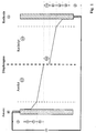
- FIG. 1 shows the schematic structure of an electrolysis cell according to the prior art
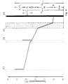
- the Fig. 2nd shows the course of the current density depending on between the electrode and the adjacent electrolyte prevailing voltage
- Fig. 3 shows schematically the structure of an embodiment of an inventive Electrolysis cell
- Fig. 4 shows the Voltage curve in an electrolysis cell according to the invention with two partial electrodes
- Fig. 5 shows one partially broken front view of an inventive Partial electrode
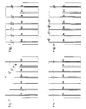
- Fig. 6 shows a cross section through this sub-electrode, which show FIGS. 7 to 10 Exemplary embodiments for voltage or current supplies of the individual partial electrodes of an inventive Electrolysis cell
- Fig. 11 shows the structure an alternative embodiment of a partial electrode from folded sieve fabrics
- Fig. 12 shows in a schematic embodiment for the dimensioning of sub-electrodes relevant sizes that Fig. 13 shows an alternative embodiment, at which the partial electrodes have different thicknesses.
- Fig. 1 also shows schematically the voltage drop of the applied cell voltage in an electrolytic cell the prior art, which the various sub-steps assigned to the electrochemical reaction sequence is.
- the total voltage required for an electrolysis process is divided into various ohmic voltage drops and voltage components for carrying out the electrode reaction.
- the voltage to be applied is the sum of all voltage drops during the operation of the electrochemical cell.
- U tot Cell voltage (electrode opposite the counter electrode) (2) U K Ohmic voltage drop in the leads of the cathode including existing cover layers up to the electrode / electrolyte interface (3)
- U A Ohmic voltage drop in the supply lines of the anode including existing cover layers up to the electrode / electrolyte interface (4)
- U ZK thermodynamic decomposition voltages on the cathode to carry out the electrochemical reaction (5)
- U ZA thermodynamic decomposition voltages at the anode to carry out the electrochemical reaction (6)
- U PK Polarization and overvoltage in the diffusion boundary layer of the cathode (7)
- U PA Polarization and overvoltage in the diffusion boundary layer of the anode (8th)
- iron (III) triethanolamine complexes in aqueous alkaline solution as a reducing agent that can be regenerated by electrochemical reduction use to reduce dyes.
- FIG. 2 shows an example of the potential range which can be used for the indirect electrochemical reduction of iron (III) -triethanolamine complexes in aqueous alkaline solution (the current density is plotted as a function of the potential difference or voltage between the electrode and the adjacent electrolyte).
- concentrations in the electrolyte are: 6 g / l (1.18.10 -2 mol / l) Fe 2 (SO 4 ) 3 .6H 2 O, 34 g / l (0.22 mol / l) triethanolamine, 20 g / l (0.5 mol / l) sodium hydroxide solution.
- a diffusion limit current of 0.35-0.40 mA / cm 2 is achieved with a liquor circulation of 145 ml / min and a cathode volume of approx. 100 ml (corresponding to 1.45 circulations / min.),
- the usable potential difference range is designated A in Fig. 2 and is, for example, 150 mV.
- the current density either drops below the diffusion limit current density or undesirable side reactions (iron deposition, hydrogen evolution) occur.
- the cell voltage in these experiments is approx. 2.2 V. If the concentration of Fe 2 (SO 4 ) 3 .6H 2 O is reduced as part of recipe optimization, the current density is further reduced to the extent that the concentration of iron (III) triethanolamine complex decreases.
- Electrode through which the electrolyte can flow in general not achieve that both the rear and also the front of the electrode in a desired one Working range of the voltage relative to the electrolyte (for example of 150 mV as shown in FIG. 2 with "A") lies.
- the situation is of course all the more critical the smaller this approved work area the voltage is relative to the adjacent electrolyte.
- the invention now essentially proposes, instead of a large three-dimensional electrode which is operated everywhere with the same cell voltage U ges , to provide a plurality of sub-electrodes which each have a different potential with respect to the counter-electrode and the thickness of the sub-electrodes 1 to vary.
- FIG. 3 shows an exemplary embodiment of an electrolytic cell according to the invention with a counter electrode 15 (cathode) and three mutually spaced equipolar sub-electrodes (anodes) T 1 , T 2 , T 3 , which according to the invention are at different potentials and through which preferably the same currents I1, I2 and I3 flow.
- the electrolyte is circulated by an external pump 14.
- the strength of the electrolyte circulation required depends, for example, on the conversion in the electrolyte (catholyte 12, anolyte 13, diaphragm 11) and has the aim of ensuring that the concentration ratios within the electrolysis cell are largely homogeneous.
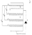
- FIG. 4 shows the voltage curve in an electrolytic cell according to the invention with two sub-electrodes T 1 and T 2 , which are at different cell voltages U GES.1 and U GES.2 compared to the counter electrode (cathode 15). Otherwise, the numerals on the right in FIG. 4 denote the same types of voltage drop as in FIG. 1, with the proviso that the subscript refers to the first partial electrode T 1 or T 2 , the second partial electrode T 2 .
- the ohmic voltage drop in the electrolyte inside the flowable electrode T 1 is identified by 21.
- the voltage drop in the electrolyte 9 2 + 21 is compensated for by a higher potential at the partial electrode T 2 compared to the partial electrode T 1 (measured in each case with respect to the cathode 15). This ensures that the electrochemically relevant voltage difference between the electrode surface and the adjacent electrolyte is essentially the same in spite of the different potential position of the electrolyte in the partial electrode T 1 , T 2 at these two partial electrodes T 1 , T 2 .
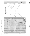
- the thickness d (cf. FIG. 12) of the sub-electrodes T 1 , T 2 , T 3 etc. will advantageously be chosen so that the potential difference between the sub-electrode and the adjacent electrolyte both on the front of the sub-electrode facing the counter electrode and on that of the Rear side of the partial electrode facing away from the counter electrode lies in the same predeterminable potential difference range.
- the predeterminable potential difference range with the width A lies between two potential difference values V 1 , V 2 .
- the upper potential difference value V 2 is determined by the fact that it does not yet have any side reactions, in particular hydrogen evolution. Such side reactions occur for potential difference values above the value V 2 and operation in this potential range is therefore undesirable.
- the lower potential difference value V 1 is determined by the fact that the desired reaction diffusion-controlled (ie essentially independent of the potential) takes place only from this point on. In the area between the two potential difference values V 1 , V 2 , the reaction thus runs in the so-called diffusion-controlled area. For each electrolysis system, the values V 1 , V 2 and thus their difference V 2 - V 1 are known or can be easily determined.
- the invention now provides for the finite To use width A of the potential difference range, around the sub-electrodes with a finite thickness (so-called three-dimensional electrode) can and still adhere to the condition that the Potential difference on the front and on the back of the partial electrode measured to the adjacent one Electrolyte in the specified potential difference range lies.
- a finite thickness allows under a larger effective electrode area (Surface in contact with the electrolyte stands) because the electrolyte also inside, for example porous or made of folded sieve fabrics Partial electrode finds an electrode surface.
- the partial electrodes must not be made as thick as desired, since one would end up with the original problem that either hydrogen evolution already starts at the front of the partial electrode while the back works normally or the front works normally and the back is essentially ineffective.
- the invention therefore proposes in a preferred embodiment that the thickness d of the partial electrodes T 1 , T 2 , T 3 is dimensioned, that the voltage drop in the electrolyte over the thickness of the respective partial electrode is between 50% and 100%, preferably between 60% and 90% of the width A of the predeterminable potential difference range A is.
- the width of the potential difference range is obtained in which the reaction proceeds satisfactorily (e.g. A 250 mV).
- the thickness values of the partial electrodes conveniently often greater than 1 cm, preferably are larger than 5 cm.
- the voltage drop per unit length in the electrolyte is also different in the area of the individual electrodes. If this is taken into account in the dimensioning rule for the thickness of the electrodes mentioned above, a preferred embodiment is obtained in which the thickness of the partial electrodes T 1 , T 2 , T 3 etc. increases with increasing distance from the counter electrode 15. In other words, in one and the same electrolytic cell, partial electrodes through which less current flows (that is, which are further away from the counterelectrode) can be built up thicker without any undesirable side effects. This allows the efficiency, in particular the effectively available electrode surface, to be increased still further.
- FIG. 13 An exemplary embodiment with partial electrodes, the thickness d 1 to d 4 of which increases with the distance from the counter electrode 15, is shown in FIG. 13.
- the effective partial electrode surface which is in contact with the electrolyte is essentially 2F, where F is the visible surface in the direction of the imaginary connecting line between the partial electrode and the counter electrode (see FIG. 12).
- F is the visible surface in the direction of the imaginary connecting line between the partial electrode and the counter electrode (see FIG. 12).
- the electrolyte also comes into contact with the electrode surfaces there, for example porous electrodes are possible.
- One or more layers can be led upwards out of the partial electrode T 1 in order to form a connecting lug 19.
- the layers of the folded screen fabric or fabrics can be connected to one another, for example, along the lines X 1 , X 2 , preferably by gluing or soldering.
- Such an electrode can be produced inexpensively on inexpensive starting materials and, in relation to the face F with a relatively small thickness d, has a high effective partial electrode surface which is in contact with the electrolyte (namely the sum of the surface of all the wires from which the screen fabric is formed). .
- the value of at least five times greater effective surface area than view surface F which is advantageous according to the invention, can thus be achieved.
- a further advantageous dimensioning of the electrodes is that the effective partial electrode surface divided by the volume V is at least 100 dm -1 .
- an electrode with a volume of 1 l then has at least an effective surface area of 1 m 2 .
- Electrodes are produced by fastening (wrapping around) copper wire strands, each consisting of a plurality of individual wires 20, on a rectangular metal frame 18 (15 strands of Cu wire each with a diameter of 0.1 mm and a strand length of 260 m).
- the effective area (total surface area of the copper wires) of a partial electrode is approx. 1m 2 .
- the thickness of such an electrode is approximately 3-4 mm.
- a change in the electrode thickness when flowing through is prevented by a plastic wire grid 17 attached to the outside of the electrode.
- copper wire instead of copper wire, other materials can also be used, restrictions mainly result from the material resistance of the electrode material.
- soldering the wire windings on the top of the electrode there is a uniform current supply 19 to the entire electrode surface.
- the electrode construction should be designed so that a uniform potential drop in the electrolyte is achieved is to make optimal use of the electrode surfaces to ensure.
- the three-dimensional Depending on the application, electrodes can be of various types Materials are manufactured.
- the structure can from electrically conductive sieve fabrics, wires, sintered plates or other porous constructions. Also the use of fixed bed / fluidized bed electrodes is possible.
- the counter electrode can be used as a common electrode for all partial electrodes are executed.
- the three-dimensional Working electrodes also include an electrode that is behind a similar working electrode is arranged with operated with the same effectiveness.
- the loss of Effectiveness which is due to the ohmic resistance in the Electrolytes can be produced, so according to the invention by slightly increasing the amount invested Cell voltage of the more distant electrodes can be avoided.
- the power supply can be from a common power supply unit operated from the each electrode with its own control device (e.g. Constant current control) with the nominal current becomes.
- 7 to 10 show possible structures of a such electrolytic cell including electrical Wiring diagram.
- the regulation of the cell voltage of the partial electrodes 16 can according to the representations separate power supply units (Fig. 7), by Ballast resistors (Fig. 8), by a common Power supply with adjustable sub-distributors (Fig. 9), by additional voltage supplies (Fig. 10).
- a large electrode area can be realized with a small space requirement (approx. 0.5 l system volume / m 2 electrode area).
- Electrode Basically, a common counter electrode Electrode are used. In appropriate areas of application is also a similar subdivision the counter electrode in partial electrodes with their own power supply possible.
- An electrolysis cell for the indirect electrochemical reduction of dispersed indigo with the aid of iron-triethanolamine complexes in an aqueous alkaline medium has two electrode spaces separated by a sound diaphragm with a square face area of 400 cm 2 .
- anode compartment content approx. 2 l
- anode such as that used for B. is used for water electrolysis or chlorine-alkali electrolysis.
- 10 cathodes with separate power supplies are installed in parallel in the cathode compartment. Design features (electrode fixation, intermediate layer made of non-conductive material) prevent contact between the partial electrodes.
- Each electrode is constructed as a wire electrode (15 strands of copper wire each with a diameter of 0.1 mm and a strand length of 260 m, the effective area of a partial electrode is approx. 1 m 2 ).
- the partial cathodes are easy to manufacture by means of wound copper wires. By connecting 10 electrodes in series, an effective total area of 10 m 2 can be achieved, the view area to the diaphragm / anode space being only 400 cm 2 .
- a flow occurs with the help of a circulation pump the partial electrodes and a thorough mixing of the cathode space, so that differences in concentration in the cathode compartment be avoided.
- the performance of the circulation pump is 14-15 l / min, so that the one located in the cathode compartment Pumped around 10 liters in less than 1 min becomes.
- the cell is powered by a Main supply unit reached, the scheme the supply currents of the sub-electrodes through downstream Partial flow controller takes place (Fig. 9.).
- the cell voltages with respect to the counter electrode (anode) differ depending on the electrode position and increase with a total current of 9 A from the electrode closest to the anode to the most distant 10th electrode as follows: Electrode no. 1 2nd 3rd 4th 5 6 7 8th 9 10th Cell voltage (V) 14.0 16.1 18.0 19.4 20.8 21.7 22.6 23.1 23.6 23.8
- the electrolyte circulation is 14-15 l / min, the cell voltage is between 4.99 and 5.51 V depending on the electrode.
- the decrease in the Cu concentration after certain time intervals is described in the following table: Time [min] 0 60 120 180 240 Cu concentration [ppm] 98.3 57.0 24.6 6.7 0.22
- a solution of 1 g / l Remazolschwarz B (Hoechst), 2.2 g / l (0.055 mol / l) NaOH and 9.1 g / l (0.028 mol / l) Na 2 SO 4 .10H 2 O are in an electrolytic cell with three electrodes electrolyzed according to the type described above (area 1 m 2 each) with a total current of 0.85 A (0.28 A per electrode).
- the electrolyte circulation is 14-15 l / min, the cell voltage is 4.1 to 4.65 V at the beginning.
- the working potential of the cathodes increases from -563 mV to -912 mV (reference electrode Ag / AgCl, 3M KCl).
- the dye solution is diluted with water and the destruction of the dye is determined by measuring the absorbance at 600 nm.
- the decrease in the color of the solution due to destruction of the dye after certain time intervals is described in the following table: Time [min] 0 15 45 60 90 Absorbance (at 600 nm) 1,938 1,788 1,138 1,015 0.719
- the invention can generally be used for the deposition of Materials, especially heavy metals from preferably use aqueous solutions, the partial electrodes, preferably consist of a different material than the material to be separated from the solution.
- the partial electrodes can then be cleaned, for example by chemical detachment or simply by changing the polarity Partial and counter electrodes are made.
- the one according to the invention is suitable Electrolysis cell also particularly suitable for carrying out Reduction and / or oxidation reactions in which the reactants remain in the dissolved system (so-called mediator technology). So it happens with these Reactions no deposition of material on the Electrodes, which are also used for fine-pored or Do not clog the fine-mesh version. It can then be sub-electrodes with great effectiveness Surface and therefore high efficiency with a long service life be used.
Landscapes
- Chemical & Material Sciences (AREA)
- Organic Chemistry (AREA)
- Chemical Kinetics & Catalysis (AREA)
- Electrochemistry (AREA)
- Materials Engineering (AREA)
- Metallurgy (AREA)
- Engineering & Computer Science (AREA)
- Electrolytic Production Of Non-Metals, Compounds, Apparatuses Therefor (AREA)
- Electrodes For Compound Or Non-Metal Manufacture (AREA)
- Electrolytic Production Of Metals (AREA)
- Fuel Cell (AREA)
- Mechanical Treatment Of Semiconductor (AREA)
- Inert Electrodes (AREA)
Description
| (1) | Uges | Zellenspannung (Elektrode gegenüber der Gegenelektrode) |
| (2) | UK | Ohmscher Spannungsabfall in den Zuleitungen der Kathode einschließlich vorhandener Deckschichten bis zur Grenzschicht Elektrode/Elektrolyt |
| (3) | UA | Ohmscher Spannungsabfall in den Zuleitungen der Anode einschließlich vorhandener Deckschichten bis zur Grenzschicht Elektrode/Elektrolyt |
| (4) | UZK | thermodynamische Zersetzungsspannungen an der Kathode zur Durchführung der elektrochemischen Reaktion |
| (5) | UZA | thermodynamische Zersetzungsspannungen an der Anode zur Durchführung der elektrochemischen Reaktion |
| (6) | UPK | Polarisation und Überspannung in der Diffusionsgrenzschichte der Kathode |
| (7) | UPA | Polarisation und Überspannung in der Diffusionsgrenzschichte der Anode |
| (8) | UEK | Ohmscher Spannungsabfall des Elektrolyten im Katholyt |
| (9) | UEA | Ohmscher Spannungsabfall des Elektrolyten im Anolyt |
| (10) | UD | Ohmscher Spannungsabfall verursacht durch das Diaphragma |
- indirekte elektrochemische Reduktion/Oxidation (z.B. von Indigodispersionen, Küpenfarbstoffen, Azofarbstoffen) mit Hilfe von Eisenkomplexsalzen
- direkte elektrochemische Reaktion von Azofarbstoffen und anderen Textilfarbstoffen zur Abwasserentfärbung
- direkte Reduktion von löslichen Azofarbstoffen
- Cyanidbeseitigung in Galvanikabwässern
- Sulfitoxidation in Prozeß- und Abwässern
- Schwermetallabreicherung in Abwässern
- präparative Aufgabenstellungen in der anorganischen/organischen Chemie
- Wasserzersetzung zur Bildung von Wasserstoff/Sauerstoff
| Elektrode Nr. | 1 | 2 | 3 | 4 | 5 | 6 | 7 | 8 | 9 | 10 |
| Zellspannung (V) | 14,0 | 16,1 | 18,0 | 19,4 | 20,8 | 21,7 | 22,6 | 23,1 | 23,6 | 23,8 |
| Zeit [min] | 0 | 60 | 120 | 180 | 240 |
| Cu-Konzentration[ppm] | 98,3 | 57,0 | 24,6 | 6,7 | 0,22 |
| Zeit [min] | 0 | 15 | 45 | 60 | 90 |
| Extinktion (bei 600 nm) | 1,938 | 1,788 | 1,138 | 1,015 | 0,719 |
Claims (24)
- Elektrolysezelle mit einem Elektrolyten, mit zwei oder mehreren elektrisch leitenden und von Elektrolyten durchströmbar aufgebauten Teilelektroden und zumindest einer dazu gegenpoligen Gegenelektrode, wobei die einzelnen Teilelektroden (T1, T2, T3) - jeweils bezüglich der Gegenelektrode (15) - auf unterschiedlichem Potential liegen, dadurch gekennzeichnet, daß die Dicke (d) der Teilelektroden (T1, T2, T3) so bemessen ist, daß die Potentialdifferenz zwischen Teilelektrode und angrenzendem Elektrolyt sowohl an der der Gegenelektrode zugewandten Vorderseite der Teilelektrode als auch an der der Gegenelektrode abgewandten Hinterseite der Teilelektrode im selben vorgebbaren Potentialdifferenzbereich (zwischen V1 und V2) liegt, wobei der vorgebbare Potentialdifferenzbereich zwischen einem unteren Potentialdifferenzwert (V1) (gemessen zwischen Teilelektrode und angrenzendem Elektrolyt) und einem oberen Potentialdifferenzwert (V2) (gemessen zwischen Teilelektrode und angrenzendem Elektrolyt) liegt, der obere Potentialdifferenzwert (V2) dadurch bestimmt ist, daß bei diesem gerade noch keine Nebenreaktionen (insbesondere Wasserstoffentwicklung) einsetzen, und der untere Potentialdifferenzwert (V1) dadurch bestimmt ist, daß erst ab diesem die gewünschte Reaktion diffusionskontrolliert abläuft, und daß die Dicke (d) der Teilelektroden (T1, T2, T3) so bemessen ist, daß der Spannungsabfall im Elektrolyten über die Dicke der jeweiligen Teilelektrode zwischen 50% und 100% der Breite des vorgebbaren Potentialdifferenzbereiches (A) beträgt.
- Elektrolysezelle nach Anspruch 1, dadurch gekennzeichnet, daß bei Verwendung von Eisen(lll)-Triethanolamin-Komplexen 6 g/l (1.18.10-2 mol/l) Fe2(SO4)3.6H2O, 34 g/l (0.22 mol/l) Triethanolamin, 20 g/l (0.5 mol/l) Natronlauge als Elektrolyt die Breite (A) des vorgebbaren Potentialdifferenzbereiches 150 mV beträgt.
- Elektrolysezelle nach Anspruch 1, dadurch gekennzeichnet, daß bei Verwendung von 3 g/l (5.09.10-3 mol/l) Fe2(SO4)3.6H2O, 25 g/l (0.153 mol/l) Bicin (N,N-bis(2-hydroxyethyl)glycin), 20 g/l (0.5 mol/l) Natronlauge als Elektrolyt die Breite des vorgebbaren Potentialdifferenzbereiches 250 mV beträgt.
- Elektrolysezelle nach Anspruch 1, dadurch gekennzeichnet, daß bei Anwendung eines Verfahrens zur Reduktion von dispergiertem Indigofarbstoff die Breite des vorgebbaren Potentialdifferenzbereiches innerhalb einer Teilelektrode bei Verwendung von Eisen(lll)triethanolaminkomplexen (6 g/l (1.18.10-2 mol/l) Fe2(SO4)3.6H2O, 34 g/l (0.22 mol/l) Triethanolamin, 20 g/l (0.5 mol/l) Natronlauge als Elektrolyt 350 mV beträgt.
- Elektrolysezelle nach einem der Ansprüche 1 bis 4, dadurch gekennzeichnet, daß die Dicke (d) der Teilelektroden (T1, T2, T3) so bemessen ist, daß der Spannungsabfall im Elektrolyten über die Dicke der jeweiligen Teilelektrode zwischen 60 % und 90% der Breite des vorgebbaren Potentialdifferenzbereiches (A) beträgt.
- Elektrolysezelle nach einem der Ansprüche 1 bis 5, dadurch gekennzeichnet, daß die elektrolytdurchlässigen Teilelektroden (T1, T2, T3) eine in Richtung der Verbindungslinie Teilelektrode-Gegenelektrode gemessene Dicke von mehr als 1 mm, vorzugsweise mehr 5 mm aufweist.
- Elektrolysezelle nach einem der Ansprüche 1 bis 6, dadurch gekennzeichnet, daß die flüssigkeitsdurchlässig ausgebildeten Teilelektroden (T1, T2, T3) zumindest teilweise aus leitenden Siebgeweben, Drähten oder Sinterplatten aufgebaut sind.
- Elektrolysezelle nach Anspruch 7, dadurch gekennzeichnet, daß zumindest eine Teilelektrode (T1, T2, T3) einen metallischen Rahmen, vorzugsweise aus im Rechteck angeordneten Profilrahmen, aufweist, um den Drähte einzeln oder in vorgefertigten Drahtbündeln herumgewickelt sind.
- Elektrolysezelle nach einem der Ansprüche 1 bis 8, dadurch gekennzeichnet, daß die Teilelektroden (T1, T2, T3) aus zwei oder mehreren elektrisch leitenden Lagen, insbesondere ausgefalteten Siebgeweben aufgebaut ist.
- Elektrolysezelle nach einem der Ansprüche 1 bis 9, dadurch gekennzeichnet, daß die Teilelektroden (T1, T2, T3) zumindest teilweise aus elektrisch leitendem porösen Material bestehen.
- Elektrolysezelle nach einem der Ansprüche 1 bis 10, dadurch gekennzeichnet, daß die Teilelektroden (T1, T2, T3) zumindest teilweise aus Schüttelektroden, Festbettelektroden oder Wirbelbettelektroden ausgebildet sind.
- Elektrolysezelle nach einem der Ansprüche 1 bis 11, dadurch gekennzeichnet, daß die Teilelektroden (T1, T2, T3) an ihrer Oberfläche mit einem Gitter aus elektrisch isolierendem Material, vorzugsweise einem Kunststoffdrahtgitter, versehen sind.
- Elektrolysezelle nach einem der Ansprüche 1 bis 12, dadurch gekennzeichnet, daß die Teilelektroden (T1- T4) einer Elektrolysezelle unterschiedliche Dicke (d1 bis d4) aufweisen.
- Elektrolysezelle nach Anspruch 13, dadurch gekennzeichnet, daß die Dicke (d1-d4) der Teilelektroden (T1 - T4) mit zunehmender Entfernung von der Gegenelektrode steigt.
- Elektrolysezelle nach einem der Ansprüche 1 bis 14, dadurch gekennzeichnet, daß die mit dem Elektrolyten in Kontakt stehende, effektive Teilelektrodenoberfläche mindestens fünfmal, vorzugsweise mindestens zehnmal größer ist als die Ansichtsfläche (F) auf die Teilelektrode.
- Elektrolysezelle nach einem der Ansprüche 1 bis 15, dadurch gekennzeichnet, daß die effektive Teilelektrodenoberfläche geteilt durch das Volumen mindestens 100 dm-1 beträgt.
- Elektrolysezelle nach einem der Ansprüche 1 bis 16, dadurch gekennzeichnet, daß zur geteilten Stromversorgung der einzelnen Teilelektroden (T1, T2, T3) getrennte Stromversorgungseinheiten vorgesehen sind (Fig. 7).
- Elektrolysezelle nach einem der Ansprüche 1 bis 16, dadurch gekennzeichnet, daß für alle Teilelektroden eine gemeinsame Spannungsquelle vorgesehen ist und zwischen dieser und den Teilelektroden verschiedene Zusatzspannungsquellen eingebaut sind (Fig. 10).
- Verwendung einer Elektrolysezelle mit einem Elektrolyten, mit zwei oder mehreren Teilelektroden und zumindest einer dazu gegenpoligen Gegenelektrode, wobei die einzelnen Teilelektroden (T1, T2, T3) - jeweils bezüglich der Gegenelektrode (15)-auf unterschiedlichem Potential liegen, nach einem der Ansprüche 1 bis 18, zur Herstellung von Eisen(ll)-Komplexen.
- Verwendung einer Elektrolysezelle mit einem Elektrolyten, mit zwei oder mehreren Teilelektroden und zumindest einer dazu gegenpoligen Gegenelektrode, wobei die einzelnen Teilelektroden (T1, T2, T3) - jeweils bezüglich der Gegenelektrode (15)-auf unterschiedlichem Potential liegen, nach einem der Ansprüche 1 bis 18, zur indirekten elektrochemischen Reduktion von dispergierten oder gelösten Farbstoffen.
- Verwendung einer Elektrolysezelle mit einem Elektrolyten, mit zwei oder mehreren Teilelektroden und zumindest einer dazu gegenpoligen Gegenelektrode, wobei die einzelnen Teilelektroden (T1, T2, T3) - jeweils bezüglich der Gegenelektrode (15)-auf unterschiedlichem Potential liegen, nach einem der Ansprüche 1 bis 18 zur Abscheidung von Materialien, Schwermetallen aus vorzugsweise wäßrigen Lösungen, wobei die Teilelektroden vorzugsweise aus einem anderen Material bestehen als das aus der Lösung abzuscheidende Material.
- Verwendung nach Anspruch 21, dadurch gekennzeichnet, daß das Reinigen der Teilelektroden durch chemisches Ablösen oder durch Umpolen der Teil- und Gegenelektroden erfolgt.
- Verwendung einer Elektrolysezelle mit einem Elektrolyten, mit zwei oder mehreren Teilelektroden und zumindest einer dazu gegenpoligen Gegenelektrode, wobei die einzelnen Teilelektroden (T1, T2, T3) - jeweils bezüglich der Gegenelektrode (15)-auf unterschiedlichem Potential liegen, nach einem der Ansprüche 1 bis 18, zur elektrochemischen Entfärbung von Abwässern.
- Verwendung einer Elektrolysezelle mit einem Elektrolyten, mit zwei oder mehreren Teilelektroden und zumindest einer dazu gegenpoligen Gegenelektrode, wobei die einzelnen Teilelektroden (T1, T2, T3) - jeweils bezüglich der Gegenelektrode (15)-auf unterschiedlichem Potential liegen, nach einem der Ansprüche 1 bis 18, zur Durchführung von Reduktions- und/oder Oxidationsreaktionen, bei denen die Reaktionspartner im gelösten System verbleiben
Applications Claiming Priority (3)
| Application Number | Priority Date | Filing Date | Title |
|---|---|---|---|
| AT0181493A AT402946B (de) | 1993-09-08 | 1993-09-08 | Elektrolysezelle |
| AT1814/93 | 1993-09-08 | ||
| PCT/AT1994/000125 WO1995007374A1 (de) | 1993-09-08 | 1994-09-07 | Electrolysezelle mit teilelektroden und zumindest einer gegenpoligen gegenelektrode |
Publications (2)
| Publication Number | Publication Date |
|---|---|
| EP0717791A1 EP0717791A1 (de) | 1996-06-26 |
| EP0717791B1 true EP0717791B1 (de) | 1998-04-29 |
Family
ID=3521567
Family Applications (1)
| Application Number | Title | Priority Date | Filing Date |
|---|---|---|---|
| EP94925304A Expired - Lifetime EP0717791B1 (de) | 1993-09-08 | 1994-09-07 | Electrolysezelle mit teilelektroden und zumindest einer gegenpoligen gegenelektrode |
Country Status (4)
| Country | Link |
|---|---|
| EP (1) | EP0717791B1 (de) |
| AT (2) | AT402946B (de) |
| DE (2) | DE9421676U1 (de) |
| WO (1) | WO1995007374A1 (de) |
Families Citing this family (6)
| Publication number | Priority date | Publication date | Assignee | Title |
|---|---|---|---|---|
| DE19919746A1 (de) * | 1999-04-29 | 2000-11-02 | Basf Ag | Verfahren zur Herstellung von wäßrig-alkalischen Lösungen reduzierter indigoider Farbstoffe |
| DE10010059A1 (de) | 2000-03-02 | 2001-09-06 | Dystar Textilfarben Gmbh & Co | Mediatorsysteme auf Basis gemischter Metallkomplexe zur Reduktion von Farbstoffen |
| DE10010060A1 (de) | 2000-03-02 | 2001-09-06 | Dystar Textilfarben Gmbh & Co | Mediatorsysteme auf Basis gemischter Metallkomplexe zur Reduktion von Farbstoffen |
| AT513319B1 (de) | 2012-08-24 | 2017-03-15 | Universität Innsbruck | Elektrode für elektrochemische Zelle |
| EP3887577B1 (de) * | 2018-11-30 | 2022-12-07 | Sedo Engineering SA | Entfernung von nebenprodukten (verunreinigungen) |
| CN111020661B (zh) * | 2019-12-20 | 2021-06-08 | 河北科技大学 | 一种用于间接电化学染色的电解体系及电化学染色工艺 |
Family Cites Families (3)
| Publication number | Priority date | Publication date | Assignee | Title |
|---|---|---|---|---|
| US3600286A (en) * | 1968-02-26 | 1971-08-17 | Selectro Chem Co | Electrolytic treatment of aqueous solutions |
| US4619749A (en) * | 1985-03-25 | 1986-10-28 | Nusbaum Ronald C | System for extracting silver from liquid solutions |
| JP3177849B2 (ja) * | 1990-12-28 | 2001-06-18 | 日本原子力研究所 | 固体電解質電解槽 |
-
1993
- 1993-09-08 AT AT0181493A patent/AT402946B/de not_active IP Right Cessation
-
1994
- 1994-09-07 EP EP94925304A patent/EP0717791B1/de not_active Expired - Lifetime
- 1994-09-07 DE DE9421676U patent/DE9421676U1/de not_active Expired - Lifetime
- 1994-09-07 AT AT94925304T patent/ATE165631T1/de active
- 1994-09-07 WO PCT/AT1994/000125 patent/WO1995007374A1/de not_active Ceased
- 1994-09-07 DE DE59405860T patent/DE59405860D1/de not_active Expired - Lifetime
Also Published As
| Publication number | Publication date |
|---|---|
| ATE165631T1 (de) | 1998-05-15 |
| WO1995007374A1 (de) | 1995-03-16 |
| DE59405860D1 (de) | 1998-06-04 |
| DE9421676U1 (de) | 1996-08-22 |
| AT402946B (de) | 1997-09-25 |
| ATA181493A (de) | 1997-02-15 |
| EP0717791A1 (de) | 1996-06-26 |
Similar Documents
| Publication | Publication Date | Title |
|---|---|---|
| DE2435185C3 (de) | Elektrolysezelle | |
| DE2547101A1 (de) | Verfahren zur gewinnung der saeure aus ihrer metallsalzloesung und hierfuer geeignete elektrolysezelle | |
| DE3043571A1 (de) | Verfahren und vorrichtung zur durchfuehrung eines elektrolytischen prozesses | |
| DE2251660A1 (de) | Verfahren und vorrichtung zur herstellung von hochreinem alkalimetallhydroxid in einer elektrolytischen zelle | |
| DE2327764A1 (de) | Verfahren zur elektrokoernung von aluminium | |
| DE2948579A1 (de) | Elektrode und verfahren zum entfernen einer metallischen substanz aus einer loesung unter verwendung dieser elektrode | |
| DE1671430B2 (de) | Vorrichtung zur elektrolyse waessriger alkalihalogenidloesungen | |
| DE2523950A1 (de) | Elektrochemische vorrichtung und ihre verwendung | |
| EP1264010A1 (de) | Verfahren und vorrichtung zum regulieren der konzentration von metallionen in einer elektrolytflüssigkeit sowie anwendung des verfahrens und verwendung der vorrichtung | |
| EP0638664A1 (de) | Verfahren und Vorrichtung zur Regenerierung einer Metallionen und Schwefelsäure enthaltenden Lösung | |
| DE2818601C2 (de) | ||
| DE3013538A1 (de) | Chloralkali-elektrolysezelle | |
| DE3324047A1 (de) | Umpolbare elektrodialyse-zelle und hierfuer geeignete elektroden | |
| DE2404167C2 (de) | Zelle zur elektrolytischen Gewinnung von Metallen sowie Metallgewinnungsverfahren | |
| EP0717791B1 (de) | Electrolysezelle mit teilelektroden und zumindest einer gegenpoligen gegenelektrode | |
| DE3808495C2 (de) | ||
| DE3401812A1 (de) | Elektrolysezelle | |
| EP1015667A2 (de) | Verfahren und vorrichtung zur konzentrationsregulierung von stoffen in elektrolyten | |
| EP0801692A2 (de) | Galvanikanlage | |
| DE2607512C2 (de) | Verfahren zur Herstellung eines Metallpulvers, Elektrolysezelle zur Durchführung des Verfahrens und Anwendung des Verfahrens | |
| DE3225470C2 (de) | ||
| EP0575699A2 (de) | Verfahren und Vorrichtung zur Regenerierung einer Metallionen und Schwefelsäure enthaltenden wässrigen Lösung sowie Verwendung | |
| DE1964661C3 (de) | Verfahren und Vorrichtung zur Herstellung eines aluminiumhaltigen Koagulierungsmittels | |
| DE1216852B (de) | Verfahren zur Elektrolyse von waessriger Salzsaeure in Diaphragmenzellen | |
| DE2419857A1 (de) | Verfahren zur elektrolyse von alkalimetallchloriden |
Legal Events
| Date | Code | Title | Description |
|---|---|---|---|
| PUAI | Public reference made under article 153(3) epc to a published international application that has entered the european phase |
Free format text: ORIGINAL CODE: 0009012 |
|
| 17P | Request for examination filed |
Effective date: 19960404 |
|
| AK | Designated contracting states |
Kind code of ref document: A1 Designated state(s): AT CH DE ES FR GB IT SE |
|
| D17P | Request for examination filed (deleted) | ||
| R17P | Request for examination filed (corrected) |
Effective date: 19960330 |
|
| 17Q | First examination report despatched |
Effective date: 19960717 |
|
| GRAG | Despatch of communication of intention to grant |
Free format text: ORIGINAL CODE: EPIDOS AGRA |
|
| GRAG | Despatch of communication of intention to grant |
Free format text: ORIGINAL CODE: EPIDOS AGRA |
|
| GRAH | Despatch of communication of intention to grant a patent |
Free format text: ORIGINAL CODE: EPIDOS IGRA |
|
| GRAH | Despatch of communication of intention to grant a patent |
Free format text: ORIGINAL CODE: EPIDOS IGRA |
|
| GRAA | (expected) grant |
Free format text: ORIGINAL CODE: 0009210 |
|
| AK | Designated contracting states |
Kind code of ref document: B1 Designated state(s): AT CH DE ES FR GB IT LI SE |
|
| PG25 | Lapsed in a contracting state [announced via postgrant information from national office to epo] |
Ref country code: IT Free format text: LAPSE BECAUSE OF FAILURE TO SUBMIT A TRANSLATION OF THE DESCRIPTION OR TO PAY THE FEE WITHIN THE PRE;WARNING: LAPSES OF ITALIAN PATENTS WITH EFFECTIVE DATE BEFORE 2007 MAY HAVE OCCURRED AT ANY TIME BEFORE 2007. THE CORRECT EFFECTIVE DATE MAY BE DIFFERENT FROM THE ONE RECORDED.SCRIBED TIME-LIMIT Effective date: 19980429 Ref country code: GB Free format text: LAPSE BECAUSE OF FAILURE TO SUBMIT A TRANSLATION OF THE DESCRIPTION OR TO PAY THE FEE WITHIN THE PRESCRIBED TIME-LIMIT Effective date: 19980429 Ref country code: FR Free format text: LAPSE BECAUSE OF FAILURE TO SUBMIT A TRANSLATION OF THE DESCRIPTION OR TO PAY THE FEE WITHIN THE PRESCRIBED TIME-LIMIT Effective date: 19980429 Ref country code: ES Free format text: THE PATENT HAS BEEN ANNULLED BY A DECISION OF A NATIONAL AUTHORITY Effective date: 19980429 |
|
| REF | Corresponds to: |
Ref document number: 165631 Country of ref document: AT Date of ref document: 19980515 Kind code of ref document: T |
|
| REG | Reference to a national code |
Ref country code: CH Ref legal event code: EP |
|
| REF | Corresponds to: |
Ref document number: 59405860 Country of ref document: DE Date of ref document: 19980604 |
|
| PG25 | Lapsed in a contracting state [announced via postgrant information from national office to epo] |
Ref country code: SE Free format text: LAPSE BECAUSE OF FAILURE TO SUBMIT A TRANSLATION OF THE DESCRIPTION OR TO PAY THE FEE WITHIN THE PRESCRIBED TIME-LIMIT Effective date: 19980729 |
|
| REG | Reference to a national code |
Ref country code: CH Ref legal event code: NV Representative=s name: ISLER & PEDRAZZINI AG |
|
| EN | Fr: translation not filed | ||
| GBV | Gb: ep patent (uk) treated as always having been void in accordance with gb section 77(7)/1977 [no translation filed] |
Effective date: 19980429 |
|
| PLBE | No opposition filed within time limit |
Free format text: ORIGINAL CODE: 0009261 |
|
| STAA | Information on the status of an ep patent application or granted ep patent |
Free format text: STATUS: NO OPPOSITION FILED WITHIN TIME LIMIT |
|
| 26N | No opposition filed | ||
| REG | Reference to a national code |
Ref country code: CH Ref legal event code: PUE Owner name: VEREIN ZUR FOERDERUNG DER FORSCHUNG UND ENTWICKLUN |
|
| REG | Reference to a national code |
Ref country code: CH Ref legal event code: PUE Owner name: DYSTAR TEXTILFARBEN GMBH & CO. DEUTSCHLAND KG Free format text: BASF AKTIENGESELLSCHAFT##67056 LUDWIGSHAFEN (DE) -TRANSFER TO- DYSTAR TEXTILFARBEN GMBH & CO. DEUTSCHLAND KG#INDUSTRIEPARK HOECHST#65926 FRANKFURT (DE) Ref country code: CH Ref legal event code: NV Representative=s name: PATENTANWAELTE SCHAAD, BALASS, MENZL & PARTNER AG |
|
| PGFP | Annual fee paid to national office [announced via postgrant information from national office to epo] |
Ref country code: DE Payment date: 20090903 Year of fee payment: 16 |
|
| PGFP | Annual fee paid to national office [announced via postgrant information from national office to epo] |
Ref country code: CH Payment date: 20100914 Year of fee payment: 17 |
|
| PGFP | Annual fee paid to national office [announced via postgrant information from national office to epo] |
Ref country code: AT Payment date: 20100910 Year of fee payment: 17 |
|
| REG | Reference to a national code |
Ref country code: DE Ref legal event code: R119 Ref document number: 59405860 Country of ref document: DE Effective date: 20110401 |
|
| PG25 | Lapsed in a contracting state [announced via postgrant information from national office to epo] |
Ref country code: DE Free format text: LAPSE BECAUSE OF NON-PAYMENT OF DUE FEES Effective date: 20110401 |
|
| REG | Reference to a national code |
Ref country code: CH Ref legal event code: PL |
|
| PG25 | Lapsed in a contracting state [announced via postgrant information from national office to epo] |
Ref country code: CH Free format text: LAPSE BECAUSE OF NON-PAYMENT OF DUE FEES Effective date: 20110930 Ref country code: LI Free format text: LAPSE BECAUSE OF NON-PAYMENT OF DUE FEES Effective date: 20110930 |
|
| REG | Reference to a national code |
Ref country code: AT Ref legal event code: MM01 Ref document number: 165631 Country of ref document: AT Kind code of ref document: T Effective date: 20110907 |
|
| PG25 | Lapsed in a contracting state [announced via postgrant information from national office to epo] |
Ref country code: AT Free format text: LAPSE BECAUSE OF NON-PAYMENT OF DUE FEES Effective date: 20110907 |