EP0716280A2 - Procédés et dispositifs de séparation d'air à basse température - Google Patents
Procédés et dispositifs de séparation d'air à basse température Download PDFInfo
- Publication number
- EP0716280A2 EP0716280A2 EP95118951A EP95118951A EP0716280A2 EP 0716280 A2 EP0716280 A2 EP 0716280A2 EP 95118951 A EP95118951 A EP 95118951A EP 95118951 A EP95118951 A EP 95118951A EP 0716280 A2 EP0716280 A2 EP 0716280A2
- Authority
- EP
- European Patent Office
- Prior art keywords
- condenser
- evaporator
- air
- rectification system
- main rectification
- Prior art date
- Legal status (The legal status is an assumption and is not a legal conclusion. Google has not performed a legal analysis and makes no representation as to the accuracy of the status listed.)
- Granted
Links
Images
Classifications
-
- F—MECHANICAL ENGINEERING; LIGHTING; HEATING; WEAPONS; BLASTING
- F25—REFRIGERATION OR COOLING; COMBINED HEATING AND REFRIGERATION SYSTEMS; HEAT PUMP SYSTEMS; MANUFACTURE OR STORAGE OF ICE; LIQUEFACTION SOLIDIFICATION OF GASES
- F25J—LIQUEFACTION, SOLIDIFICATION OR SEPARATION OF GASES OR GASEOUS OR LIQUEFIED GASEOUS MIXTURES BY PRESSURE AND COLD TREATMENT OR BY BRINGING THEM INTO THE SUPERCRITICAL STATE
- F25J3/00—Processes or apparatus for separating the constituents of gaseous or liquefied gaseous mixtures involving the use of liquefaction or solidification
- F25J3/02—Processes or apparatus for separating the constituents of gaseous or liquefied gaseous mixtures involving the use of liquefaction or solidification by rectification, i.e. by continuous interchange of heat and material between a vapour stream and a liquid stream
- F25J3/04—Processes or apparatus for separating the constituents of gaseous or liquefied gaseous mixtures involving the use of liquefaction or solidification by rectification, i.e. by continuous interchange of heat and material between a vapour stream and a liquid stream for air
- F25J3/04006—Providing pressurised feed air or process streams within or from the air fractionation unit
- F25J3/04078—Providing pressurised feed air or process streams within or from the air fractionation unit providing pressurized products by liquid compression and vaporisation with cold recovery, i.e. so-called internal compression
- F25J3/04103—Providing pressurised feed air or process streams within or from the air fractionation unit providing pressurized products by liquid compression and vaporisation with cold recovery, i.e. so-called internal compression using solely hydrostatic liquid head
-
- F—MECHANICAL ENGINEERING; LIGHTING; HEATING; WEAPONS; BLASTING
- F25—REFRIGERATION OR COOLING; COMBINED HEATING AND REFRIGERATION SYSTEMS; HEAT PUMP SYSTEMS; MANUFACTURE OR STORAGE OF ICE; LIQUEFACTION SOLIDIFICATION OF GASES
- F25J—LIQUEFACTION, SOLIDIFICATION OR SEPARATION OF GASES OR GASEOUS OR LIQUEFIED GASEOUS MIXTURES BY PRESSURE AND COLD TREATMENT OR BY BRINGING THEM INTO THE SUPERCRITICAL STATE
- F25J3/00—Processes or apparatus for separating the constituents of gaseous or liquefied gaseous mixtures involving the use of liquefaction or solidification
- F25J3/02—Processes or apparatus for separating the constituents of gaseous or liquefied gaseous mixtures involving the use of liquefaction or solidification by rectification, i.e. by continuous interchange of heat and material between a vapour stream and a liquid stream
- F25J3/04—Processes or apparatus for separating the constituents of gaseous or liquefied gaseous mixtures involving the use of liquefaction or solidification by rectification, i.e. by continuous interchange of heat and material between a vapour stream and a liquid stream for air
- F25J3/04006—Providing pressurised feed air or process streams within or from the air fractionation unit
- F25J3/04078—Providing pressurised feed air or process streams within or from the air fractionation unit providing pressurized products by liquid compression and vaporisation with cold recovery, i.e. so-called internal compression
- F25J3/04084—Providing pressurised feed air or process streams within or from the air fractionation unit providing pressurized products by liquid compression and vaporisation with cold recovery, i.e. so-called internal compression of nitrogen
-
- F—MECHANICAL ENGINEERING; LIGHTING; HEATING; WEAPONS; BLASTING
- F25—REFRIGERATION OR COOLING; COMBINED HEATING AND REFRIGERATION SYSTEMS; HEAT PUMP SYSTEMS; MANUFACTURE OR STORAGE OF ICE; LIQUEFACTION SOLIDIFICATION OF GASES
- F25J—LIQUEFACTION, SOLIDIFICATION OR SEPARATION OF GASES OR GASEOUS OR LIQUEFIED GASEOUS MIXTURES BY PRESSURE AND COLD TREATMENT OR BY BRINGING THEM INTO THE SUPERCRITICAL STATE
- F25J3/00—Processes or apparatus for separating the constituents of gaseous or liquefied gaseous mixtures involving the use of liquefaction or solidification
- F25J3/02—Processes or apparatus for separating the constituents of gaseous or liquefied gaseous mixtures involving the use of liquefaction or solidification by rectification, i.e. by continuous interchange of heat and material between a vapour stream and a liquid stream
- F25J3/04—Processes or apparatus for separating the constituents of gaseous or liquefied gaseous mixtures involving the use of liquefaction or solidification by rectification, i.e. by continuous interchange of heat and material between a vapour stream and a liquid stream for air
- F25J3/04006—Providing pressurised feed air or process streams within or from the air fractionation unit
- F25J3/04078—Providing pressurised feed air or process streams within or from the air fractionation unit providing pressurized products by liquid compression and vaporisation with cold recovery, i.e. so-called internal compression
- F25J3/0409—Providing pressurised feed air or process streams within or from the air fractionation unit providing pressurized products by liquid compression and vaporisation with cold recovery, i.e. so-called internal compression of oxygen
-
- F—MECHANICAL ENGINEERING; LIGHTING; HEATING; WEAPONS; BLASTING
- F25—REFRIGERATION OR COOLING; COMBINED HEATING AND REFRIGERATION SYSTEMS; HEAT PUMP SYSTEMS; MANUFACTURE OR STORAGE OF ICE; LIQUEFACTION SOLIDIFICATION OF GASES
- F25J—LIQUEFACTION, SOLIDIFICATION OR SEPARATION OF GASES OR GASEOUS OR LIQUEFIED GASEOUS MIXTURES BY PRESSURE AND COLD TREATMENT OR BY BRINGING THEM INTO THE SUPERCRITICAL STATE
- F25J3/00—Processes or apparatus for separating the constituents of gaseous or liquefied gaseous mixtures involving the use of liquefaction or solidification
- F25J3/02—Processes or apparatus for separating the constituents of gaseous or liquefied gaseous mixtures involving the use of liquefaction or solidification by rectification, i.e. by continuous interchange of heat and material between a vapour stream and a liquid stream
- F25J3/04—Processes or apparatus for separating the constituents of gaseous or liquefied gaseous mixtures involving the use of liquefaction or solidification by rectification, i.e. by continuous interchange of heat and material between a vapour stream and a liquid stream for air
- F25J3/04248—Generation of cold for compensating heat leaks or liquid production, e.g. by Joule-Thompson expansion
- F25J3/04284—Generation of cold for compensating heat leaks or liquid production, e.g. by Joule-Thompson expansion using internal refrigeration by open-loop gas work expansion, e.g. of intermediate or oxygen enriched (waste-)streams
- F25J3/0429—Generation of cold for compensating heat leaks or liquid production, e.g. by Joule-Thompson expansion using internal refrigeration by open-loop gas work expansion, e.g. of intermediate or oxygen enriched (waste-)streams of feed air, e.g. used as waste or product air or expanded into an auxiliary column
- F25J3/04296—Claude expansion, i.e. expanded into the main or high pressure column
-
- F—MECHANICAL ENGINEERING; LIGHTING; HEATING; WEAPONS; BLASTING
- F25—REFRIGERATION OR COOLING; COMBINED HEATING AND REFRIGERATION SYSTEMS; HEAT PUMP SYSTEMS; MANUFACTURE OR STORAGE OF ICE; LIQUEFACTION SOLIDIFICATION OF GASES
- F25J—LIQUEFACTION, SOLIDIFICATION OR SEPARATION OF GASES OR GASEOUS OR LIQUEFIED GASEOUS MIXTURES BY PRESSURE AND COLD TREATMENT OR BY BRINGING THEM INTO THE SUPERCRITICAL STATE
- F25J3/00—Processes or apparatus for separating the constituents of gaseous or liquefied gaseous mixtures involving the use of liquefaction or solidification
- F25J3/02—Processes or apparatus for separating the constituents of gaseous or liquefied gaseous mixtures involving the use of liquefaction or solidification by rectification, i.e. by continuous interchange of heat and material between a vapour stream and a liquid stream
- F25J3/04—Processes or apparatus for separating the constituents of gaseous or liquefied gaseous mixtures involving the use of liquefaction or solidification by rectification, i.e. by continuous interchange of heat and material between a vapour stream and a liquid stream for air
- F25J3/04406—Processes or apparatus for separating the constituents of gaseous or liquefied gaseous mixtures involving the use of liquefaction or solidification by rectification, i.e. by continuous interchange of heat and material between a vapour stream and a liquid stream for air using a dual pressure main column system
- F25J3/04412—Processes or apparatus for separating the constituents of gaseous or liquefied gaseous mixtures involving the use of liquefaction or solidification by rectification, i.e. by continuous interchange of heat and material between a vapour stream and a liquid stream for air using a dual pressure main column system in a classical double column flowsheet, i.e. with thermal coupling by a main reboiler-condenser in the bottom of low pressure respectively top of high pressure column
-
- F—MECHANICAL ENGINEERING; LIGHTING; HEATING; WEAPONS; BLASTING
- F25—REFRIGERATION OR COOLING; COMBINED HEATING AND REFRIGERATION SYSTEMS; HEAT PUMP SYSTEMS; MANUFACTURE OR STORAGE OF ICE; LIQUEFACTION SOLIDIFICATION OF GASES
- F25J—LIQUEFACTION, SOLIDIFICATION OR SEPARATION OF GASES OR GASEOUS OR LIQUEFIED GASEOUS MIXTURES BY PRESSURE AND COLD TREATMENT OR BY BRINGING THEM INTO THE SUPERCRITICAL STATE
- F25J3/00—Processes or apparatus for separating the constituents of gaseous or liquefied gaseous mixtures involving the use of liquefaction or solidification
- F25J3/02—Processes or apparatus for separating the constituents of gaseous or liquefied gaseous mixtures involving the use of liquefaction or solidification by rectification, i.e. by continuous interchange of heat and material between a vapour stream and a liquid stream
- F25J3/04—Processes or apparatus for separating the constituents of gaseous or liquefied gaseous mixtures involving the use of liquefaction or solidification by rectification, i.e. by continuous interchange of heat and material between a vapour stream and a liquid stream for air
- F25J3/04642—Recovering noble gases from air
- F25J3/04648—Recovering noble gases from air argon
- F25J3/04654—Producing crude argon in a crude argon column
- F25J3/04666—Producing crude argon in a crude argon column as a parallel working rectification column of the low pressure column in a dual pressure main column system
- F25J3/04672—Producing crude argon in a crude argon column as a parallel working rectification column of the low pressure column in a dual pressure main column system having a top condenser
-
- F—MECHANICAL ENGINEERING; LIGHTING; HEATING; WEAPONS; BLASTING
- F25—REFRIGERATION OR COOLING; COMBINED HEATING AND REFRIGERATION SYSTEMS; HEAT PUMP SYSTEMS; MANUFACTURE OR STORAGE OF ICE; LIQUEFACTION SOLIDIFICATION OF GASES
- F25J—LIQUEFACTION, SOLIDIFICATION OR SEPARATION OF GASES OR GASEOUS OR LIQUEFIED GASEOUS MIXTURES BY PRESSURE AND COLD TREATMENT OR BY BRINGING THEM INTO THE SUPERCRITICAL STATE
- F25J2245/00—Processes or apparatus involving steps for recycling of process streams
- F25J2245/40—Processes or apparatus involving steps for recycling of process streams the recycled stream being air
-
- Y—GENERAL TAGGING OF NEW TECHNOLOGICAL DEVELOPMENTS; GENERAL TAGGING OF CROSS-SECTIONAL TECHNOLOGIES SPANNING OVER SEVERAL SECTIONS OF THE IPC; TECHNICAL SUBJECTS COVERED BY FORMER USPC CROSS-REFERENCE ART COLLECTIONS [XRACs] AND DIGESTS
- Y10—TECHNICAL SUBJECTS COVERED BY FORMER USPC
- Y10S—TECHNICAL SUBJECTS COVERED BY FORMER USPC CROSS-REFERENCE ART COLLECTIONS [XRACs] AND DIGESTS
- Y10S62/00—Refrigeration
- Y10S62/923—Inert gas
- Y10S62/924—Argon
Definitions
- the invention relates to a method and a device for the low-temperature separation of air, in which a first partial stream of compressed and purified air is cooled, fed to a main rectification system and broken down there into liquid oxygen and gaseous nitrogen, a liquid product fraction being separated into a first condenser-evaporator indirect heat exchange evaporates with a second partial flow of compressed and purified air, the second partial flow at least partially condenses in the indirect heat exchange in the first condenser-evaporator and an argon-containing oxygen fraction from the main rectification system is fed to a crude argon column and separated there into crude argon and into an oxygen-rich residual liquid and wherein gaseous crude argon from the top of the crude argon column by indirect heat exchange with at least a portion of the second substream downstream of the first condenser-evaporator in a second condenser nsator-evaporator is liquefied, wherein at least a part of the second partial stream evaporates in the second conden
- the main rectification system of an air separator in which oxygen and nitrogen are obtained, comprises at least one, often two rectification columns. Processes with evaporation of a liquid product fraction are shown in EP-A-341854 and EP-B-93448. In most known processes, the air condensed against the evaporating oxygen (often completely or almost completely) is fed liquid into one of the rectification columns. Due to their composition, this must be done at the middle of the column, i.e. above the sump and below the head. This feeding of liquid at an intermediate level interferes with rectification and leads to a reduction in product purity and / or yield.
- the invention is therefore based on the object of making the method and the device of the type mentioned particularly economical and in particular a particularly high product purity and / or a particularly high product yield with a particularly low outlay in terms of apparatus and operation and / or with a particularly low energy consumption to reach.
- This object is achieved in a first variant of the invention in that all or essentially all of the cold required for the liquefaction of crude argon is made available by the evaporation of the second partial stream.
- the amount of refrigeration required to liquefy raw argon corresponds at least to the heat of vaporization of the return flow for the raw argon column. If liquid argon is withdrawn from the liquid argon column, the amount of refrigeration for the quantity of product can also be added, for example if the product is liquefied in the second condenser-evaporator; alternatively, the product liquefaction of the crude argon can also be carried out using another refrigerant, preferably in a separate condenser.
- By “essentially the total” is meant at least 90%, preferably at least 95%, most preferably at least 99% of this amount of refrigeration.
- the remaining amount of refrigeration can be supplied to the evaporation side of the second condenser evaporator, for example, by feeding a small amount of another liquid fraction (e.g. sump or intermediate liquid from one of the columns).
- a single heat exchanger is preferably used as the second condenser-evaporator. In terms of equipment, it can also be implemented by more than one block, the evaporation spaces communicating with one another.
- the nitrogen content of the liquefied air in the second partial stream is higher than that in the bottom liquid from one of the columns of the main rectification system, which is usually evaporated in the top condenser of the crude argon column.
- the head of the crude argon column can thus be moved at a particularly low pressure, for example 1.10 to 1.20 bar, preferably approximately 1.15 bar.
- the separation performance of the crude argon column can be improved, or you can use (cheaper) mass transfer elements with higher pressure loss per theoretical plate and still achieve a high separation effect.
- the object described above is achieved in a second variant of the invention in that at least part (for example 80 to 100 mol%, preferably 95 to 100 mol%) of the second partial stream evaporated in the indirect heat exchange in the second condenser-evaporator without further pressure increase in the main rectification system is initiated.
- at least part for example 80 to 100 mol%, preferably 95 to 100 mol%
- the largest part of the evaporated second partial flow or the entire evaporated second partial flow is fed into the or one of the rectification columns of the main rectification system.
- the liquid product fraction can be produced by any air component or by any mixture consisting of air components be formed, for example by oxygen or nitrogen or by an intermediate such as crude argon, which contains small amounts of oxygen and / or nitrogen in addition to argon.
- air components for example by oxygen or nitrogen or by an intermediate such as crude argon, which contains small amounts of oxygen and / or nitrogen in addition to argon.
- the liquid can be removed, for example, from a rectification column or a storage or buffer tank.
- the first condenser-evaporator can be the main heat exchanger, in which the gaseous products are heated against feed air, or a separate heat exchanger (secondary condenser).
- the second partial air flow can contain, for example, 35 to 45 mol%, preferably 35 to 40 mol% of the total amount of feed air; the rest of the feed air or part of it forms the first partial air flow.
- the invention can advantageously be applied to a double-column process, that is to say if the main rectification system has a pressure column and a low-pressure column.
- the first partial air flow is introduced into the pressure column and the argon-containing oxygen fraction is withdrawn from the low pressure column.
- the liquid product fraction against which the second partial air flow condenses is preferably formed by a liquid oxygen flow from the low-pressure column.
- the entire liquefied second partial air stream can be passed into the second condenser-evaporator, the steam generated therein being partially or completely passed into a rectification column (for example the low-pressure column of a double column).
- gaseous oxygen is to be obtained under increased pressure
- the pressure of the liquid product fraction is increased upstream of the indirect heat exchange with the second partial stream.
- the compression of the gaseous product can be saved in whole or in part; Overall, the so-called internal compression produces one or more printed products such as pressurized oxygen, pressurized nitrogen and / or raw argon under pressure in a particularly economical manner.
- the second partial flow during indirect heat exchange with the liquid oxygen flow is at a pressure which is higher than the highest pressure in the main rectification system, for example under a supercritical pressure; the pressure of the second partial air flow can, for example, be 30 to 55 bar, preferably 45 to 52 bar, above the highest pressure in the main rectification system (e.g. the operating pressure of a pressure column).
- the liquefaction temperature of the air condensing against the evaporating product fraction can thus be adapted to the evaporation temperature of the product fraction.
- a total product quantity is withdrawn in liquid form from the main rectification system.
- the proportion relates to the standard volume. This liquid removal can take place both by leading out of the rectification column or columns in the liquid state and subsequent external evaporation, preferably under pressure (for example evaporation of the liquid product fraction in the first condenser-evaporator), or by removal as a liquid product, for example for storage in Tanks.
- the proportion of 21% can be achieved, for example, by evaporating the entire oxygen product in the first condenser-evaporator and additionally obtaining a small amount of nitrogen and / or oxygen as a liquid product.
- a third partial stream of compressed and cleaned air is preferably expanded while performing work and fed to the main rectification system. Its amount is, for example, 0 to 45 mol%, preferably 15 to 40 mol% of the total feed air; the second partial air flow contains, for example, 35 to 45 mol%, preferably 35 to 40 mol% of the total amount of feed air; the rest of the feed air forms the first partial air flow.
- the third partial flow can be branched off, for example, from the second partial flow, preferably downstream of a secondary compressor, which brings the second partial flow to a pressure above the maximum pressure of the main rectification system.
- the third partial flow can also be branched off from the first or even identical to the first partial flow.
- the relaxed third partial stream is preferably fed into the pressure column.
- the work-relieving expansion of the third partial flow (for example after branching off from the first partial flow) can also lead from pressure column pressure to low pressure column pressure; the relaxed air must then be led into the low pressure column.
- Another liquid product stream can be vaporized in an indirect heat exchange with compressed and purified air in a favorable manner.
- a smaller liquid stream of nitrogen and / or raw argon can exchange latent heat with condensing air, for example with the second partial air stream.
- a device for the low-temperature separation of air according to claims 10 to 12 is also part of the invention.
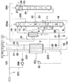
- a first partial flow 101 of compressed and cleaned air 1 is cooled under a pressure of 5 to 10 bar, preferably 5.5 to 6.5 bar in a main heat exchanger 2 in indirect heat exchange with product flows to approximately dew point.
- the main rectification system has a double column 4 with a pressure column 5 (5 to 10 bar, preferably 5.5 to 6.5 bar), a low pressure column 6 (1.3 to 2 bar, preferably 1.5 to 1.7 bar) and an intermediate main condenser 7 on. Bottom liquid 9 from the pressure column 5 is subcooled in a counterflow 8 against product flows of the low pressure column and fed into the low pressure column 6 (line 10).
- Gaseous nitrogen 11 from the top of the pressure column 5 is liquefied in the main condenser 7 against evaporating liquid in the sump of the low pressure column 6.
- Some of the condensate 12 is fed as a return to the pressure column 5 (line 13) and another part 14 is fed into the low-pressure column 6 after supercooling 8 (FIG. 15).
- Low pressure nitrogen 16 and impure nitrogen 17 are heated to about ambient temperature after removal from the low pressure column 6 in the heat exchangers 8 and 2.
- Product oxygen is withdrawn as a liquid oxygen stream 18 from the bottom of the low-pressure column 6 and brought to an increased pressure of, for example, 5 to 80 bar by means of a pump 19, depending on the product pressure required.
- a pump 19 depending on the product pressure required.
- other methods for increasing the pressure in the liquid phase can also be used, for example by utilizing a hydrostatic potential or by pressure build-up evaporation in a storage tank.
- the liquid high-pressure oxygen 20 is evaporated in the main heat exchanger 2 and drawn off as an internally compressed gaseous product 21.
- a second partial stream 201, 202 of the compressed and cleaned air is condensed against the evaporating product stream after it has been brought to a pressure of 12 to 60 bar, preferably 15 to 40 bar, in a post-compressor 206.
- An argon-containing oxygen fraction 22 from the low-pressure column 6 is broken down in a raw argon column 24 into raw argon at the top of the column and into an oxygen-rich residual liquid. The latter is fed back into the low-pressure column 6 via line 23, possibly conveyed by a pump. To generate return 25 and possibly to obtain liquid raw argon 26, the gaseous raw argon is liquefied in a top condenser 27 by indirect heat exchange. (The crude argon product can alternatively or additionally be withdrawn as a gas.)
- the liquefied second partial stream 203/204 is passed to the evaporation side of the top condenser 27 of the crude argon column and there evaporates.
- the second partial flow is previously subcooled in counterflow 8 and throttled to approximately low-pressure column pressure (for example by means of an expansion valve, not shown).
- the steam generated during the indirect heat exchange with crude argon is passed via line 205 to the low-pressure column 6 and / or via 205a into the product line 17 for impure nitrogen.
- liquid nitrogen is led from the pressure column via lines 28 and 29 to the main heat exchanger 2 and is withdrawn as a gaseous product via line 30.
- the liquid nitrogen can be internally compressed if necessary, for example by a pump 31.
- An additional liquid product that is vaporized against highly compressed air is, for example, liquid crude argon, which is required in gaseous form under increased pressure.
- Raw argon - like the nitrogen and oxygen streams to be vaporized - can either be taken from a column or from a buffer or storage tank.
- the invention is particularly applicable to the raw argon internal compression according to EP-A-171711, EP-B-331028 or EP-B-363861.
- the pressure of the condensing air must in principle depend on the highest evaporation temperature.
- the evaporation temperature of the internally compressed nitrogen 29 is higher than that of the internally compressed oxygen 20, but the amount of liquid nitrogen to be evaporated is significantly less than the amount of liquid oxygen, it is possible to adjust the air pressure to the lower of the two evaporation temperatures.
- the evaporation of the liquid product (s) against the second partial flow of air can also be carried out in one or more secondary condensers, which are separate from the main heat exchanger, in a departure from the illustration in the drawing.
- Part of the oxygen product can be obtained as a liquid product (line 33); it is also possible to remove a certain amount of oxygen in gaseous form from the low-pressure column 6 and to heat it in the main heat exchanger 2 (not shown in the drawing).
- a third partial flow 301 can be branched off from the post-compressed second partial flow 202, relaxed in a work-performing manner (turbine 32) and introduced into the main rectification system, preferably into the pressure column 5.
Landscapes
- Engineering & Computer Science (AREA)
- Physics & Mathematics (AREA)
- Mechanical Engineering (AREA)
- Thermal Sciences (AREA)
- General Engineering & Computer Science (AREA)
- Health & Medical Sciences (AREA)
- Emergency Medicine (AREA)
- Separation By Low-Temperature Treatments (AREA)
Applications Claiming Priority (2)
| Application Number | Priority Date | Filing Date | Title |
|---|---|---|---|
| DE4443190 | 1994-12-05 | ||
| DE4443190A DE4443190A1 (de) | 1994-12-05 | 1994-12-05 | Verfahren und Vorrichtung zur Tieftemperaturzerlegung von Luft |
Publications (3)
| Publication Number | Publication Date |
|---|---|
| EP0716280A2 true EP0716280A2 (fr) | 1996-06-12 |
| EP0716280A3 EP0716280A3 (fr) | 1997-04-16 |
| EP0716280B1 EP0716280B1 (fr) | 2001-05-16 |
Family
ID=6534925
Family Applications (1)
| Application Number | Title | Priority Date | Filing Date |
|---|---|---|---|
| EP95118951A Expired - Lifetime EP0716280B1 (fr) | 1994-12-05 | 1995-12-01 | Procédé et dispositif de séparation d'air à basse température |
Country Status (7)
| Country | Link |
|---|---|
| US (1) | US5644934A (fr) |
| EP (1) | EP0716280B1 (fr) |
| JP (1) | JPH08233458A (fr) |
| KR (1) | KR960024196A (fr) |
| CN (1) | CN1125838A (fr) |
| DE (2) | DE4443190A1 (fr) |
| TW (1) | TW299244B (fr) |
Cited By (1)
| Publication number | Priority date | Publication date | Assignee | Title |
|---|---|---|---|---|
| EP0828122A1 (fr) | 1996-09-06 | 1998-03-11 | Linde Aktiengesellschaft | Procédé et dispositif pour l'obtention d'argon par séparation d'air à basse température |
Families Citing this family (26)
| Publication number | Priority date | Publication date | Assignee | Title |
|---|---|---|---|---|
| US6202441B1 (en) | 1999-05-25 | 2001-03-20 | Air Liquide Process And Construction, Inc. | Cryogenic distillation system for air separation |
| US6276170B1 (en) * | 1999-05-25 | 2001-08-21 | Air Liquide Process And Construction | Cryogenic distillation system for air separation |
| US6347534B1 (en) | 1999-05-25 | 2002-02-19 | Air Liquide Process And Construction | Cryogenic distillation system for air separation |
| US6196024B1 (en) * | 1999-05-25 | 2001-03-06 | L'air Liquide, Societe Anonyme Pour L'etude Et L'exploitation Des Procedes Georges Claude | Cryogenic distillation system for air separation |
| DE102007031759A1 (de) | 2007-07-07 | 2009-01-08 | Linde Ag | Verfahren und Vorrichtung zur Erzeugung von gasförmigem Druckprodukt durch Tieftemperaturzerlegung von Luft |
| DE102007031765A1 (de) | 2007-07-07 | 2009-01-08 | Linde Ag | Verfahren zur Tieftemperaturzerlegung von Luft |
| DE102009034979A1 (de) | 2009-04-28 | 2010-11-04 | Linde Aktiengesellschaft | Verfahren und Vorrichtung zur Erzeugung von gasförmigem Drucksauerstoff |
| EP2312248A1 (fr) | 2009-10-07 | 2011-04-20 | Linde Aktiengesellschaft | Procédé et dispositif de production d'oxygène sous pression et de crypton/xénon |
| DE102010052545A1 (de) | 2010-11-25 | 2012-05-31 | Linde Aktiengesellschaft | Verfahren und Vorrichtung zur Gewinnung eines gasförmigen Druckprodukts durch Tieftemperaturzerlegung von Luft |
| DE102010052544A1 (de) | 2010-11-25 | 2012-05-31 | Linde Ag | Verfahren zur Gewinnung eines gasförmigen Druckprodukts durch Tieftemperaturzerlegung von Luft |
| EP2520886A1 (fr) | 2011-05-05 | 2012-11-07 | Linde AG | Procédé et dispositif de production d'un produit comprimé à oxygène gazeux par décomposition à basse température d'air |
| DE102011112909A1 (de) | 2011-09-08 | 2013-03-14 | Linde Aktiengesellschaft | Verfahren und Vorrichtung zur Gewinnung von Stahl |
| US10222120B2 (en) * | 2011-09-20 | 2019-03-05 | Linde Aktiengesellschaft | Method and device for generating two purified partial air streams |
| EP2600090B1 (fr) | 2011-12-01 | 2014-07-16 | Linde Aktiengesellschaft | Procédé et dispositif destinés à la production d'oxygène sous pression par décomposition à basse température de l'air |
| DE102011121314A1 (de) | 2011-12-16 | 2013-06-20 | Linde Aktiengesellschaft | Verfahren zur Erzeugung eines gasförmigen Sauerstoff-Druckprodukts durch Tieftemperaturzerlegung von Luft |
| DE102012017488A1 (de) | 2012-09-04 | 2014-03-06 | Linde Aktiengesellschaft | Verfahren zur Erstellung einer Luftzerlegungsanlage, Luftzerlegungsanlage und zugehöriges Betriebsverfahren |
| WO2014154339A2 (fr) | 2013-03-26 | 2014-10-02 | Linde Aktiengesellschaft | Procédé de séparation d'air et installation de séparation d'air |
| EP2784420A1 (fr) | 2013-03-26 | 2014-10-01 | Linde Aktiengesellschaft | Procédé de séparation de l'air et installation de séparation de l'air |
| EP2801777A1 (fr) | 2013-05-08 | 2014-11-12 | Linde Aktiengesellschaft | Installation de décomposition de l'air dotée d'un entraînement de compresseur principal |
| DE102013017590A1 (de) | 2013-10-22 | 2014-01-02 | Linde Aktiengesellschaft | Verfahren zur Gewinnung eines Krypton und Xenon enthaltenden Fluids und hierfür eingerichtete Luftzerlegungsanlage |
| PL2963369T3 (pl) | 2014-07-05 | 2018-10-31 | Linde Aktiengesellschaft | Sposób i urządzenie do niskotemperaturowej separacji powietrza |
| PL2963370T3 (pl) | 2014-07-05 | 2018-11-30 | Linde Aktiengesellschaft | Sposób i urządzenie do kriogenicznego rozdziału powietrza |
| EP2963371B1 (fr) | 2014-07-05 | 2018-05-02 | Linde Aktiengesellschaft | Procede et dispositif de production d'un produit de gaz sous pression par decomposition a basse temperature d'air |
| EP2963367A1 (fr) | 2014-07-05 | 2016-01-06 | Linde Aktiengesellschaft | Procédé et dispositif cryogéniques de séparation d'air avec consommation d'énergie variable |
| CN105758114A (zh) * | 2014-12-19 | 2016-07-13 | 常熟市永安工业气体制造有限公司 | 氩气制备装置 |
| JP6440232B1 (ja) * | 2018-03-20 | 2018-12-19 | レール・リキード−ソシエテ・アノニム・プール・レテュード・エ・レクスプロワタシオン・デ・プロセデ・ジョルジュ・クロード | 製品窒素ガスおよび製品アルゴンの製造方法およびその製造装置 |
Citations (5)
| Publication number | Priority date | Publication date | Assignee | Title |
|---|---|---|---|---|
| US4715873A (en) * | 1986-04-24 | 1987-12-29 | Air Products And Chemicals, Inc. | Liquefied gases using an air recycle liquefier |
| US5049174A (en) * | 1990-06-18 | 1991-09-17 | Air Products And Chemicals, Inc. | Hybrid membrane - cryogenic generation of argon concurrently with nitrogen |
| US5245831A (en) * | 1992-02-13 | 1993-09-21 | Air Products And Chemicals, Inc. | Single heat pump cycle for increased argon recovery |
| US5469710A (en) * | 1994-10-26 | 1995-11-28 | Praxair Technology, Inc. | Cryogenic rectification system with enhanced argon recovery |
| EP0684438A1 (fr) * | 1994-05-27 | 1995-11-29 | The BOC Group plc | Séparation de l'air |
Family Cites Families (12)
| Publication number | Priority date | Publication date | Assignee | Title |
|---|---|---|---|---|
| EP0093448B1 (fr) * | 1982-05-03 | 1986-10-15 | Linde Aktiengesellschaft | Procédé et dispositif pour obtenir de l'oxygène gazeux sous pression élevée |
| DE3428968A1 (de) * | 1984-08-06 | 1986-02-13 | Linde Ag, 6200 Wiesbaden | Verfahren und vorrichtung zur zerlegung von rohargon |
| US4871382A (en) * | 1987-12-14 | 1989-10-03 | Air Products And Chemicals, Inc. | Air separation process using packed columns for oxygen and argon recovery |
| DE3840506A1 (de) * | 1988-12-01 | 1990-06-07 | Linde Ag | Verfahren und vorrichtung zur luftzerlegung |
| US5049173A (en) * | 1990-03-06 | 1991-09-17 | Air Products And Chemicals, Inc. | Production of ultra-high purity oxygen from cryogenic air separation plants |
| US5108476A (en) * | 1990-06-27 | 1992-04-28 | Union Carbide Industrial Gases Technology Corporation | Cryogenic air separation system with dual temperature feed turboexpansion |
| US5159816A (en) * | 1991-05-14 | 1992-11-03 | Air Products And Chemicals, Inc. | Method of purifying argon through cryogenic adsorption |
| US5315833A (en) * | 1991-10-15 | 1994-05-31 | Liquid Air Engineering Corporation | Process for the mixed production of high and low purity oxygen |
| US5365741A (en) * | 1993-05-13 | 1994-11-22 | Praxair Technology, Inc. | Cryogenic rectification system with liquid oxygen boiler |
| DE4317916A1 (de) * | 1993-05-28 | 1994-12-01 | Linde Ag | Verfahren und Vorrichtung zur Gewinnung von Argon |
| US5440884A (en) * | 1994-07-14 | 1995-08-15 | Praxair Technology, Inc. | Cryogenic air separation system with liquid air stripping |
| US5522224A (en) * | 1994-08-15 | 1996-06-04 | Praxair Technology, Inc. | Model predictive control method for an air-separation system |
-
1994
- 1994-12-05 DE DE4443190A patent/DE4443190A1/de not_active Withdrawn
-
1995
- 1995-11-29 JP JP7332550A patent/JPH08233458A/ja active Pending
- 1995-12-01 DE DE59509262T patent/DE59509262D1/de not_active Expired - Fee Related
- 1995-12-01 EP EP95118951A patent/EP0716280B1/fr not_active Expired - Lifetime
- 1995-12-01 TW TW084112821A patent/TW299244B/zh active
- 1995-12-04 US US08/566,701 patent/US5644934A/en not_active Expired - Fee Related
- 1995-12-05 CN CN95117579A patent/CN1125838A/zh active Pending
- 1995-12-05 KR KR1019950046689A patent/KR960024196A/ko not_active Application Discontinuation
Patent Citations (5)
| Publication number | Priority date | Publication date | Assignee | Title |
|---|---|---|---|---|
| US4715873A (en) * | 1986-04-24 | 1987-12-29 | Air Products And Chemicals, Inc. | Liquefied gases using an air recycle liquefier |
| US5049174A (en) * | 1990-06-18 | 1991-09-17 | Air Products And Chemicals, Inc. | Hybrid membrane - cryogenic generation of argon concurrently with nitrogen |
| US5245831A (en) * | 1992-02-13 | 1993-09-21 | Air Products And Chemicals, Inc. | Single heat pump cycle for increased argon recovery |
| EP0684438A1 (fr) * | 1994-05-27 | 1995-11-29 | The BOC Group plc | Séparation de l'air |
| US5469710A (en) * | 1994-10-26 | 1995-11-28 | Praxair Technology, Inc. | Cryogenic rectification system with enhanced argon recovery |
Cited By (1)
| Publication number | Priority date | Publication date | Assignee | Title |
|---|---|---|---|---|
| EP0828122A1 (fr) | 1996-09-06 | 1998-03-11 | Linde Aktiengesellschaft | Procédé et dispositif pour l'obtention d'argon par séparation d'air à basse température |
Also Published As
| Publication number | Publication date |
|---|---|
| CN1125838A (zh) | 1996-07-03 |
| JPH08233458A (ja) | 1996-09-13 |
| TW299244B (fr) | 1997-03-01 |
| DE59509262D1 (de) | 2001-06-21 |
| EP0716280A3 (fr) | 1997-04-16 |
| KR960024196A (ko) | 1996-07-20 |
| DE4443190A1 (de) | 1996-06-13 |
| EP0716280B1 (fr) | 2001-05-16 |
| US5644934A (en) | 1997-07-08 |
Similar Documents
| Publication | Publication Date | Title |
|---|---|---|
| EP0716280B1 (fr) | Procédé et dispositif de séparation d'air à basse température | |
| EP0955509B1 (fr) | Procédé et appareil pour la production d'oxygène à haute pureté | |
| EP2235460B1 (fr) | Procédé et installation pour la séparation cryogénique d'air | |
| EP1243882B1 (fr) | Production d'argon dans un système de séparation d'air à triple pression et une colonne d'argon | |
| EP1308680B1 (fr) | Procédé et dispositif de production de krypton et/ou xénon par distillation cryogénique de l'air | |
| DE10139727A1 (de) | Verfahren und Vorrichtung zur Gewinnung eines Druckprodukts durch Tieftemperaturzerlegung von Luft | |
| EP0948730B1 (fr) | Procede et dispositif de production d'azote comprime | |
| DE10013073A1 (de) | Verfahren und Vorrichtung zur Tieftemperaturzerlegung von Luft | |
| EP1357342A1 (fr) | Système de séparation d'air cryogénique à trois colonnes avec production d'argon | |
| DE10018200A1 (de) | Verfahren und Vorrichtung zur Gewinnung von Druckstickstoff durch Tieftemperaturzerlegung von Luft | |
| WO2016131545A1 (fr) | Procédé et dispositif d'obtention d'un produit d'azote comprimé | |
| WO2020169257A1 (fr) | Procédé et installation de décomposition d'air à basse température | |
| EP0669508A1 (fr) | Procédé et appareil permettant d'obtenir de l'argon pur | |
| EP2322888B1 (fr) | Procédé et dispositif d'obtention d'un concentré d'hélium-néon à partir d'air | |
| EP0768503B1 (fr) | Procédé de séparation d'air à triple colonne | |
| DE10103968A1 (de) | Drei-Säulen-System zur Tieftemperaturzerlegung von Luft | |
| DE60008455T2 (de) | Tieftemperaturdestillationsanlage zur Luftzerleggung | |
| DE19855487A1 (de) | Verfahren und Vorrichtung zur Gewinnung von Drucksauerstoff und Krypton/Xenon durch Tieftemperaturzerlegung von Luft | |
| WO2020244801A1 (fr) | Procédé et installation de décomposition d'air à basse température | |
| EP1199532B1 (fr) | Système de séparation d'air cryogénique à trois colonnes | |
| DE19933558A1 (de) | Dreisäulenverfahren und -vorrichtung zur Tieftemperaturzerlegung von Luft | |
| DE19819338A1 (de) | Verfahren und Vorrichtung zur Gewinnung von hochreinem Druckstickstoff | |
| DE10045121A1 (de) | Verfahren und Vorrichtung zur Gewinnung eines gasförmigen Produkts durch Tieftemperaturzerlegung von Luft | |
| EP1050728B1 (fr) | Procedé et installation de séparation des gaz de l'air à une seule colonne | |
| DE19819263A1 (de) | Verfahren und Vorrichtung zur Gewinnung von Druckstickstoff |
Legal Events
| Date | Code | Title | Description |
|---|---|---|---|
| PUAI | Public reference made under article 153(3) epc to a published international application that has entered the european phase |
Free format text: ORIGINAL CODE: 0009012 |
|
| AK | Designated contracting states |
Kind code of ref document: A2 Designated state(s): BE DE FR GB IT |
|
| PUAL | Search report despatched |
Free format text: ORIGINAL CODE: 0009013 |
|
| AK | Designated contracting states |
Kind code of ref document: A3 Designated state(s): BE DE FR GB IT |
|
| 17P | Request for examination filed |
Effective date: 19970612 |
|
| 17Q | First examination report despatched |
Effective date: 19990526 |
|
| GRAG | Despatch of communication of intention to grant |
Free format text: ORIGINAL CODE: EPIDOS AGRA |
|
| RTI1 | Title (correction) |
Free format text: METHOD AND APPARATUS FOR THE LOW TEMPERATURE AIR SEPARATION |
|
| GRAG | Despatch of communication of intention to grant |
Free format text: ORIGINAL CODE: EPIDOS AGRA |
|
| GRAH | Despatch of communication of intention to grant a patent |
Free format text: ORIGINAL CODE: EPIDOS IGRA |
|
| GRAH | Despatch of communication of intention to grant a patent |
Free format text: ORIGINAL CODE: EPIDOS IGRA |
|
| GRAA | (expected) grant |
Free format text: ORIGINAL CODE: 0009210 |
|
| AK | Designated contracting states |
Kind code of ref document: B1 Designated state(s): BE DE FR GB IT |
|
| PG25 | Lapsed in a contracting state [announced via postgrant information from national office to epo] |
Ref country code: IT Free format text: LAPSE BECAUSE OF FAILURE TO SUBMIT A TRANSLATION OF THE DESCRIPTION OR TO PAY THE FEE WITHIN THE PRE;WARNING: LAPSES OF ITALIAN PATENTS WITH EFFECTIVE DATE BEFORE 2007 MAY HAVE OCCURRED AT ANY TIME BEFORE 2007. THE CORRECT EFFECTIVE DATE MAY BE DIFFERENT FROM THE ONE RECORDED.SCRIBED TIME-LIMIT Effective date: 20010516 |
|
| REF | Corresponds to: |
Ref document number: 59509262 Country of ref document: DE Date of ref document: 20010621 |
|
| GBT | Gb: translation of ep patent filed (gb section 77(6)(a)/1977) |
Effective date: 20010731 |
|
| ET | Fr: translation filed | ||
| PG25 | Lapsed in a contracting state [announced via postgrant information from national office to epo] |
Ref country code: BE Free format text: LAPSE BECAUSE OF NON-PAYMENT OF DUE FEES Effective date: 20011231 |
|
| REG | Reference to a national code |
Ref country code: GB Ref legal event code: IF02 |
|
| PLBE | No opposition filed within time limit |
Free format text: ORIGINAL CODE: 0009261 |
|
| STAA | Information on the status of an ep patent application or granted ep patent |
Free format text: STATUS: NO OPPOSITION FILED WITHIN TIME LIMIT |
|
| 26N | No opposition filed | ||
| BERE | Be: lapsed |
Owner name: LINDE A.G. Effective date: 20011231 |
|
| PGFP | Annual fee paid to national office [announced via postgrant information from national office to epo] |
Ref country code: GB Payment date: 20071128 Year of fee payment: 13 Ref country code: FR Payment date: 20071210 Year of fee payment: 13 |
|
| PGFP | Annual fee paid to national office [announced via postgrant information from national office to epo] |
Ref country code: DE Payment date: 20071129 Year of fee payment: 13 |
|
| REG | Reference to a national code |
Ref country code: FR Ref legal event code: CA |
|
| GBPC | Gb: european patent ceased through non-payment of renewal fee |
Effective date: 20081201 |
|
| REG | Reference to a national code |
Ref country code: FR Ref legal event code: ST Effective date: 20090831 |
|
| PG25 | Lapsed in a contracting state [announced via postgrant information from national office to epo] |
Ref country code: DE Free format text: LAPSE BECAUSE OF NON-PAYMENT OF DUE FEES Effective date: 20090701 |
|
| PG25 | Lapsed in a contracting state [announced via postgrant information from national office to epo] |
Ref country code: GB Free format text: LAPSE BECAUSE OF NON-PAYMENT OF DUE FEES Effective date: 20081201 |
|
| PG25 | Lapsed in a contracting state [announced via postgrant information from national office to epo] |
Ref country code: FR Free format text: LAPSE BECAUSE OF NON-PAYMENT OF DUE FEES Effective date: 20081231 |