EP0715375B1 - Modular electrical assembly - Google Patents
Modular electrical assembly Download PDFInfo
- Publication number
- EP0715375B1 EP0715375B1 EP95402628A EP95402628A EP0715375B1 EP 0715375 B1 EP0715375 B1 EP 0715375B1 EP 95402628 A EP95402628 A EP 95402628A EP 95402628 A EP95402628 A EP 95402628A EP 0715375 B1 EP0715375 B1 EP 0715375B1
- Authority
- EP
- European Patent Office
- Prior art keywords
- end piece
- assembly according
- female end
- gutters
- opening
- Prior art date
- Legal status (The legal status is an assumption and is not a legal conclusion. Google has not performed a legal analysis and makes no representation as to the accuracy of the status listed.)
- Revoked
Links
- 230000007935 neutral effect Effects 0.000 claims description 17
- 238000005192 partition Methods 0.000 claims description 7
- 230000005611 electricity Effects 0.000 claims description 5
- 210000002105 tongue Anatomy 0.000 claims description 5
- 230000000903 blocking effect Effects 0.000 claims 1
- 239000004020 conductor Substances 0.000 description 11
- 238000003780 insertion Methods 0.000 description 5
- 230000037431 insertion Effects 0.000 description 5
- 238000009434 installation Methods 0.000 description 4
- 239000012212 insulator Substances 0.000 description 4
- 238000012423 maintenance Methods 0.000 description 4
- 230000009471 action Effects 0.000 description 3
- 238000009826 distribution Methods 0.000 description 3
- 238000010616 electrical installation Methods 0.000 description 3
- 230000004308 accommodation Effects 0.000 description 1
- 238000013459 approach Methods 0.000 description 1
- 230000008901 benefit Effects 0.000 description 1
- 230000001680 brushing effect Effects 0.000 description 1
- 230000000295 complement effect Effects 0.000 description 1
- 238000005520 cutting process Methods 0.000 description 1
- 238000013461 design Methods 0.000 description 1
- 239000000463 material Substances 0.000 description 1
- 238000000465 moulding Methods 0.000 description 1
- 230000036961 partial effect Effects 0.000 description 1
- 238000003825 pressing Methods 0.000 description 1
- 230000003405 preventing effect Effects 0.000 description 1
- 230000000284 resting effect Effects 0.000 description 1
- 239000011435 rock Substances 0.000 description 1
Images


Classifications
-
- H—ELECTRICITY
- H02—GENERATION; CONVERSION OR DISTRIBUTION OF ELECTRIC POWER
- H02G—INSTALLATION OF ELECTRIC CABLES OR LINES, OR OF COMBINED OPTICAL AND ELECTRIC CABLES OR LINES
- H02G3/00—Installations of electric cables or lines or protective tubing therefor in or on buildings, equivalent structures or vehicles
- H02G3/02—Details
- H02G3/08—Distribution boxes; Connection or junction boxes
- H02G3/14—Fastening of cover or lid to box
-
- H—ELECTRICITY
- H01—ELECTRIC ELEMENTS
- H01R—ELECTRICALLY-CONDUCTIVE CONNECTIONS; STRUCTURAL ASSOCIATIONS OF A PLURALITY OF MUTUALLY-INSULATED ELECTRICAL CONNECTING ELEMENTS; COUPLING DEVICES; CURRENT COLLECTORS
- H01R25/00—Coupling parts adapted for simultaneous co-operation with two or more identical counterparts, e.g. for distributing energy to two or more circuits
- H01R25/006—Coupling parts adapted for simultaneous co-operation with two or more identical counterparts, e.g. for distributing energy to two or more circuits the coupling part being secured to apparatus or structure, e.g. duplex wall receptacle
Definitions
- the present invention relates to electrical equipment made up of modular elements of various functions provided cooperative means of mechanical interconnection and electric.
- Said cooperative interconnection means allow directly assemble said modular elements to others without requiring any tool or element complementary so as to constitute a strip.
- Such equipment offers a range of modular elements allowing to carry out all electrical installations these elements may for example include sockets, circuit breakers, switches, indicator lights, fuses or filters.
- Modular elements have one or more elements identical or not functional.
- EP-A-0 498 405 describes a modular current distribution strip system electric, in which an element comprising the contacts has front faces forming pedestals of sockets and ends respectively male and female, assembled end to end, so that they can form a strip of arbitrary length.
- the invention provides electrical equipment similar to a strip made up of modular elements of various functions, said modular elements being provided with cooperating mechanical interconnection means and electric to assemble them directly to others, characterized in that said elements modules consist of a front panel having at least a specific function, a contact support in which are mounted the means necessary for distribution electricity, a male end and a female end comprising mechanical and electrical connection means.
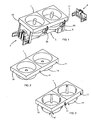
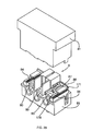
- Figure 1 is shown a following modular element the invention which is generally parallelepipedic. he has a front face 1 shaped so as to provide a or functional elements, two sockets according to French standard in the example of Figure 1 and a contact support 5 in which the means are mounted necessary for the distribution of electricity.
- This modular element also has male means for connection on one of its short sides and means connection females, not visible in figure 1, on the other of its short sides.
- connection elements provide the electrical connections and mechanical between the modular elements and are worn by a male end 2 and by a female end 3 which will be described in more detail later.
- a safety cap 4 is provided to ensure the closing the female end 3 and prohibiting access to means of electrical connection which it comprises.
- Elastic tabs 50 fixed on the contact support 2 are arranged along the periphery of the element modular. These legs are intended to ensure the maintenance of the modular element in a rail or any other similar device, they also allow the maintenance in place of ornamental plates around the front face.
- the upper face of the front face is rectangular and surrounded by a falling edge 10. Notches 11 are practiced in this falling edge 10 so as to allow the passage of a small tool in order to push the elastic tabs 50 towards the module when it must be separated from the holding means or of ornament to which it was snapped.
- Figures 2 and 3 show two examples of realization of a modular element front face. These figures show front panels for two elements functional, socket outlets, corresponding respectively to the French standard and to the German standard. These front faces 1 have housings cylindrical 14 for the insertion of current plugs. The housings 14 of the bases according to the German standard have notches 14 'for the passage of the release tabs Earth.
- Front panels of different shapes are provided to to equip the modular elements according to the functions they supply.
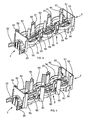
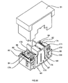
- Figures 4 and 5 show modular elements offering three socket outlets, corresponding French standard and standard respectively German, without the front panel.
- the contact supports 5 are generally formed of a base 55 and uprights 51.
- a contact support for sockets according to the German standard is shown in Figure 5 it is made by adding to the contact support for sockets current according to French standard, amounts 51 'intended when fitting the grounding tabs.
- the base 55 is shaped so as to support the electrical conductors consisting of phase bar 60, earth bar 61 and neutral bar 62.
- the earth bar 61 carries earth plugs 64 while in the example in figure 5, the earth bar 61 carries stirrups 65.
- the base 55 has cylindrical portions 54 between which the uprights 51 are positioned.
- the uprights 52 arranged at one end of the support of contacts 5 are shaped so as to allow the fixing the male end piece 2, while the uprights 53 arranged at the opposite end are shaped so as to allow the attachment of the female end piece 3. They have for this purpose flat portions in the end plane of the contact support.
- FIG. 6 representing a front face 1 seen from below, shows that the underside of the cylindrical housings 14 carries a cell shutter box 16.
- the cell shutter 7 shown in Figures 8 and 9 is a shutter of known type and will be briefly described below.
- This shutter 7 is generally T-shaped.
- the crossbar 73 is arranged in front the openings 18 provided for the passage of the plugs phase and neutral, the tilted bosses 75 are turned towards the upper face of the front face 1 while the bosses 78 are turned towards the housing 16.
- the arms 77 are arranged on either side of the earth plug through opening 17.
- the shutter bears on its face lower rib 72 on which it rocks when is not subject to a symmetrical action on the part of phase and neutral pins of the plug current.
- This shutter 7 is pushed back into the closed position by a spring not shown positioned around the lug 71 and resting in the housing 19 of the housing 16.
- the underside of the front face 1 also has ribs 12, 13 intended to bear against the upper ends of the contact support uprights 5 or against the base 55 thereof when mounting said front face on said contact support.
- ribs are not shown in more detail in drawing, they are generally flat and shaped trapezoidal.
- Bosses 15 of low height are still provided under the front face 1. These bosses 15 are arranged facing each other notches 11 and are intended for holding the tabs elastic 50 recessed.
- FIG. 34 Such a position is visible in Figure 34 on which the modular element is shown arranged in a rail 9.
- the tab 50 on the right is in its open position to which it maintains the modular element in rail 9 while the left tab has been pushed back behind brushing 15 by the introduction of a tool in a notch 11 not shown.
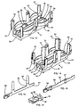
- the base 55 of the support of contacts 5 presents three gutters 56, 57 and 58 for the installation of conductive bars 60 to 62.
- the central gutter 57 receives the earth bar while that the side gutters receive the phase bars and neutral.
- gutters are partially in place closed by walls 90 arranged in pairs perpendicular to the walls of the gutters and leaving between them a narrow passage in which is inserted the current bar so that said walls 90 are supports for holding in position of said bars.
- the conductive bars rest on bars 91 of low height crossing the gutters.
- Gutters 56 and 58 intended for the phase bar and the neutral bar are wider than the gutter intended for the earth bar so as to allow the provision of the accommodation 67 necessary for the insertion of phase and neutral plugs of the socket, they have a width equal to the maximum diameter that can have the housings when a plug is inserted.
- phase and neutral gutters have housings 59 into which the ends can penetrate phase and neutral pins when plugged into the base of a plug.
- the conductive bars are for example made from a sheet of conductive material folded in half in the sense of length.
- FIG. 15 shows an earth bar 61, carrying the earth plugs 64 according to French standard. These sheets of earth 64 are mounted on brackets 66 ensuring the positioning of the earth plug 64 above the phase gutter 56 while the neutral bar is arranged in the middle of the contact support.
- the bracket 65 is fixed to the earth bar 61 while being angled so as to bring the earth elements against the uprights 51 'of the contact support.
- the consoles 66 must pass over the bar of phase and the stirrups 65 should pass over the phase bar and neutral bar.
- An earth conductor insulator 92 such as that shown in Figure 15 ', is arranged for a base to the French standard, between consoles 66 of the earth bar and the phase bar so as to avoid short circuits between these bars.
- two such earth conductor insulators 92 will be placed between each stirrup 65 and the phase bar on the one hand, the neutral bar on the other.
- a phase bar 60 is shown in Figure 16. It is made of a folded sheet of conductive material in half lengthwise so as to be consisting of two blades positioned one against the other, each blade having bosses forming the housings 67 regularly distributed. It also presents notches 68 along its upper edge to allow the installation of the earth conductor insulator 92.
- the neutral bar has not been shown in the drawing.
- the neutral bar has notches 68 and housing 67 distributed over its length.
- the relative arrangement of these notches and housings is different in order to take into account the places occupied by neutral cells and the 65 stirrup of earth.
- a clamp 69 is fixed to one end of the bars current. This clamp forms a female element of the electrical connection to be made between elements modular.
- these female electrical elements are arranged in the end piece male 2 while the male electrical elements formed by the flat ends of the current bars are arranged in the female end 3.
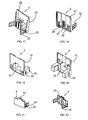
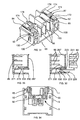
- Figures 17 and 18 show the male end respectively seen from outside the modular element and from inside said element.
- This male end piece 2 has a flat face 21 intended for be fixed on the uprights 52 arranged at the end of the contact support 5 to form an end wall ( Figures 4 and 5).
- These snap-on means consist of two tabs latching 20 provided with elastic tabs 22 located in the example shown on the outer side of this face plane 21 and on either side thereof.
- This positioning of the latching means makes it possible to reduce the size of the nozzle.
- a boss 23 In the center of this planar face 21, and always on the face external of the latter, is arranged a boss 23 divided into three cavities 26, 27 and 28 by vertical walls of thin. These three cavities are, when the nozzle male is fixed to the contact support, arranged in the extension of gutters 56 to 58. Clamps 69 fixed at the ends of the contact bars 60 to 62 are then the interior of the cavities 26 to 28.
- the surfaces of the cavity central 27 are, in the example shown, provided with grooves to allow good quality molding of the part taking into account the large thickness of material present on these walls.
- the female end piece shown in Figures 19 and 20 includes also a flat face 31 intended to form the wall end of the contact support 5 while being fixed to the amounts 53.
- This female end piece 3 has housings 30 extending to from the internal face of said planar face 31. These dwellings are of a size suitable for the insertion of latching tabs 20 of a male end piece 2. said housings 30 have lights 32 in which are position the elastic tabs 22.
- the female end piece 3 is crossed by an opening 33 of dimensions substantially equal to the external dimensions of the boss 23 of the male end piece. This opening 33 is, when the female end-piece is fixed to the contact support, arranged in front of the gutters 56 to 58 and the ends flat contact bars extend across it up to the level of the flat face 31.
- the user chooses the modular elements bearing the functional elements that it needs. he then secures these modular elements to each other by inserting the latching lugs 20 and the boss 23 of the male end of one of the elements in the housings 30 and the opening 33 of the female end of another element. In doing so, the cooperation of the legs latching 20 with the housings 30 and the boss 23 with the opening 33 ensures positioning and maintenance mechanics of modular elements while clamps 69 positioned in the boss of the male end cap tighten the flat ends disposed in the opening 33 of the endpiece female and ensure the electrical connection of the two elements.
- the power supply electrical elements is done by the male end which provides assemblies of modular elements, the last ends with the flat outer wall of a nozzle female.
- a safety plug 4 such as that shown in Figures 21 and 22 is put in place.
- This safety plug 4 is similar to a male end piece 2. It has a flat and full face 41 which can, as shown, be of such dimensions as it covers only the lower part comprising the opening 33 of the flat face 31 of the female end piece.
- boss 43 and latching lugs 40 of same dimensions as boss 23 and legs snaps 20 of the male end piece.
- This safety cap 4 can thus be adapted to the female end piece in the same way as a male end piece and close the opening 33.
- the elastic tabs 22 or 42 of the snap tabs 20 or 40 are positioned in the lights 32 of housing 30.
- FIGS 23 to 27 show different variants of realizations of legs 20 and 40 and housings 30.
- the latching tabs 120 have a folded portion giving them a U shape.
- the folded portion is very long so as to provide a support tab 121 extending outside the housing 130 when the connection is made.
- the elastic tab 120 also has a suitable lug 122 to enter a light 132 of the housing.
- the folded part of the tab 120 has a tongue 124 carrying a lug 123 on its external face.
- the housing 130 has a light 134 in which can penetrate the tongue 124.
- a groove 133 of width at the less equal to the thickness of the lug 123 connects said light on the open face of the housing 130.
- the user has not need to have a tool, he just has to hold one of the elements in one hand by pressing the support tab 121 or on lug 123 and the other element in its other hand, and pull in opposite directions to separate said elements.
- the folded part of the tab 120 has a lug 126 adapted to penetrate a light 136 and a boss 125.
- the housing 130 has at its bottom an opening 135 in which are disengaged means such as a pusher possibly fitted with a spring recall so as to press the folded part of the lug by the action of this pusher on the boss 125.
- the pin 126 thus emerges from the light 136.
- the part folded back the tab 120 carries a rounded boss 127 entering a light 137 in the housing 130.
- the rounded shape of the boss 127 makes it possible to separate the elements by simply pulling on them.
- the folded parts of the legs 120 and the openings 132 to 134 and 136, 137 can be directed outside the modular elements as shown in the figures previous, but can also be directed to the underside of said modular elements.
- the paws elastic 20 of Figures 1 to 22 could also be directed towards the lower face of the modular elements.
- the part folded back the tab 120 can be arranged in any desired direction since the user does not need to be there access.
- this terminal block 8 comprises a front face 81 and a contact support 85.
- the front face 81 of the terminal block has a closed upper wall in order to prohibit any access inside the terminal block when it is installed.
- the contact support 85 carries three means for fixing the cables not shown by which the current is supplied electric. These means are, in the example shown, screw studs 80.
- the end of the terminal block to which the modular elements is called female end 83.
- This female end 83 has an opening 133 crossed by conductive strips 86 and housings 130 with a light 132 similar to the opening 33 and to the housings 30 of the female end pieces 3 of the elements modular.
- the male end piece 2 of a modular element can thus be connected to this female end 83.
- the terminal block is fitted with a movable partition called a shutter terminal block 87 which is positioned in the plane of the end female 83 when no element is connected to the terminal block, and thus masks the conductive strips 86.
- Terminal block shutter 87 is pushed to this position rest for which it masks the conductive blades 86 by springs 84 arranged in housings formed by ribs 82 of the contact support 85.
- This terminal blocker 87 has a flat face 170 of same dimensions as the opening 133. Said planar face 170 is crossed by three rectangular slots 176 intended when the conductive strips 86 pass.
- Arms 171 are arranged on either side of the face plane 170, they carry support plates 172 for support springs 84 and holding plates 174 to ensure maintaining said springs 84 in their housings.
- the arms 171 also carry elastic tabs 178 with curved ends.
- These elastic tabs 178 are adapted to come in support against shoulders 88 of contact support 85 to keep the shutter 87 in its rest position against the forces exerted on it by the springs 84.
- the boss 23 of the male end piece bears against shutter 87 and pushes it back against the springs in order to enter the opening 133.
- the terminal blocker is in the position shown in Figure 31 for which the blades 86 are discovered.
- the clamps 69 present in this boss 23 come position around the conductive strips 86 to ensure the electrical connection.
- Figures 32 and 33 are alternative embodiments of the terminal block and male end piece to maintain the terminal blocker in its rest position both that a male nozzle is not approached.
- terminal blocker 287 carries arms 271 terminated by a lug 272.
- the terminal block contact support has a housing 230 having a window 232 in its wall separating it from opening 233 in which the blades are positioned conductors 86.
- the pin 272 is thus positioned in the window 232 of the housing 230 which ensures the maintenance of the shutter 287 in its rest position as long as one intentional action to free him is not carried out.
- the housing 230 also has a boss 231 on its opposite side of window 232.
- Elastic legs curved in U 220 are provided hard the boss 223 of the male end piece.
- the legs 220 of the male end piece can be those ensuring mechanical connection or lugs additional.
- the legs 271 of the terminal block shutter have bosses rounded 273 positioned in lights 233 of housing 230.
- each female end fitting is equipped a movable partition or end cap of the same type that the terminal blocker described above which makes safety caps not essential, at least in the implementation of variants such as those of Figures 32 and 33 for which the shutter is held in its rest position.
Description
La présente invention concerne un appareillage électrique constitué d'éléments modulaires de fonctions variées munis de moyens coopérants d'interconnexion mécanique et électrique.The present invention relates to electrical equipment made up of modular elements of various functions provided cooperative means of mechanical interconnection and electric.
Lesdits moyens coopérants d'interconnexion permettent d'assembler directement lesdits éléments modulaires les uns aux autres sans nécessiter d'outil ou d'élement complémentaire de manière à constituer une réglette.Said cooperative interconnection means allow directly assemble said modular elements to others without requiring any tool or element complementary so as to constitute a strip.
Un tel appareillage propose une gamme d'éléments modulaires permettant de réaliser toutes les installations électriques habituelles, ces éléments peuvent par exemple comporter des prises de courant, des disjoncteurs, des interrupteurs, des voyants lumineux, des fusibles ou des filtres.Such equipment offers a range of modular elements allowing to carry out all electrical installations these elements may for example include sockets, circuit breakers, switches, indicator lights, fuses or filters.
Les éléments modulaires comportent un ou plusieurs éléments fonctionnels identiques ou non.Modular elements have one or more elements identical or not functional.
EP-A-0 498 405 décrit un système modulaire de réglette de distribution de courant électrique, dans lequel un élément comportant les contacts présente des faces- avant formant socles de prises de courant et des extrémités respectivement mâles et femelles, assemblables bout à bout, de sorte à pouvoir former une réglette de longueur arbitraire.EP-A-0 498 405 describes a modular current distribution strip system electric, in which an element comprising the contacts has front faces forming pedestals of sockets and ends respectively male and female, assembled end to end, so that they can form a strip of arbitrary length.
L'invention propose un appareillage électrique analogue à une réglette constitué par assemblage d'éléments modulaires de fonctions variées, lesdits éléments modulaires étant munis de moyens coopérants d'interconnexion mécanique et électrique permettant de les assembler directement les uns aux autres, caractérisé en ce que lesdits éléments modulaires sont constitués d'une face avant ayant au moins une fonction déterminée, d'un support de contacts dans lequel sont montés les moyens nécessaires à la distribution de l'électricité, d'un embout mâle et d'un embout femelle comportant les moyens de connexion mécanique et électrique.The invention provides electrical equipment similar to a strip made up of modular elements of various functions, said modular elements being provided with cooperating mechanical interconnection means and electric to assemble them directly to others, characterized in that said elements modules consist of a front panel having at least a specific function, a contact support in which are mounted the means necessary for distribution electricity, a male end and a female end comprising mechanical and electrical connection means.
L'appareillage selon l'invention est encore remarquable en ce que :
- le support de contacts présente trois gouttières pour la mise en place de barres de courant,
- la gouttière centrale reçoit la barre de terre tandis que les gouttières latérales reçoivent les barres de phase et de neutre,
- les gouttières sont de place en place partiellement obturées par des parois disposées par paires perpendiculairement aux parois des gouttières et laissant entre elles un passage étroit dans lequel est insérée la barre conductrice,
- l'embout mâle comporte une face plane destinée à être fixée à l'extrémité du support de contact afin d'en former une paroi d'extrémité et des moyens d'encliquetage pour sa solidarisation à un embout femelle,
- les moyens d'encliquetage sont constitués par deux pattes d'encliquetage munies de languettes élastiques,
- un bossage divisé en trois cavités est disposé au centre de la face plane dudit embout mâle, les trois cavités étant disposées dans le prolongement des gouttières,
- l'embout femelle comporte une face plane destinée à former une paroi d'extrémité du support de contact et des logements pour l'insertion des moyens d'encliquetage d'un embout mâle,
- l'embout femelle est traversé par une ouverture de dimensions sensiblement égales aux dimensions externes du bossage de l'embout mâle, disposée en face des gouttières,
- des pinces fixées aux extrémités des barres de contact sont à l'intérieur des cavités de l'embout mâle et les extrémités plates des barres de contact s'étendent à travers l'ouverture de l'embout femelle,
- un bouchon de sécurité de forme semblable à un embout mâle est fixé dans l'embout femelle afin d'éviter que l'usager puisse toucher les extrémités plates des barres qui sont disposées dans l'ouverture,
- chaque embout femelle est équipé d'une cloison mobile ou obturateur d'embout,
- l'appareillage comporte un bornier pour l'alimentation en courant électrique des éléments modulaires comportant une face avant fermée et un support de contacts portant trois moyens de fixation des câbles par lesquels est fourni le courant électrique solidarisés à des lames conductrices visibles dans l'extrémité femelle du bornier à laquelle seront raccordés les éléments modulaires,
- l'extrémité femelle du bornier présente une ouverture traversée par les lames conductrices et des logements semblables à l'ouverture et aux logements des embouts femelles des éléments modulaires de manière à pouvoir connecter à cette extrémité femelle l'embout mâle d'un élément modulaire,
- le bornier est muni d'une cloison mobile ou obturateur de bornier qui est positionnée dans le plan de l'extrémité femelle lorsqu'aucun élément n'est raccordé au bornier, et masque les lames conductrices,
- les cloisons mobiles utilisées pour obturer l'embout femelle et/ou le bornier sont maintenues dans leur position de repos,
- des moyens de désencliquetage sont prévus pour le déverrouillage des moyens d'encliquetage.
- the contact support has three gutters for the installation of current bars,
- the central gutter receives the earth bar while the lateral gutters receive the phase and neutral bars,
- the gutters are partially closed from place to place by walls arranged in pairs perpendicular to the walls of the gutters and leaving between them a narrow passage in which the busbar is inserted,
- the male end piece has a flat face intended to be fixed to the end of the contact support in order to form an end wall and latching means for its fastening to a female end piece,
- the latching means consist of two latching tabs provided with elastic tongues,
- a boss divided into three cavities is placed in the center of the flat face of said male end piece, the three cavities being arranged in the extension of the gutters,
- the female end piece has a flat face intended to form an end wall of the contact support and housings for the insertion of the latching means of a male end piece,
- the female end-piece is traversed by an opening of dimensions substantially equal to the external dimensions of the boss of the male end-piece, arranged opposite the gutters,
- clamps fixed to the ends of the contact bars are inside the cavities of the male end piece and the flat ends of the contact bars extend through the opening of the female end piece,
- a safety cap similar in shape to a male end piece is fixed in the female end piece to prevent the user from touching the flat ends of the bars which are arranged in the opening,
- each female end fitting is fitted with a movable partition or end cap shutter,
- the switchgear comprises a terminal block for the supply of electric current to the modular elements comprising a closed front face and a contact support carrying three means for fixing the cables by which the electric current is supplied secured to conductive blades visible in the end female of the terminal block to which the modular elements will be connected,
- the female end of the terminal block has an opening traversed by the conductive blades and housings similar to the opening and housings of the female end pieces of the modular elements so as to be able to connect to this female end the male end piece of a modular element,
- the terminal block is fitted with a movable partition or terminal blocker which is positioned in the plane of the female end when no element is connected to the terminal block, and hides the conductive strips,
- the movable partitions used to close the female end-piece and / or the terminal block are kept in their rest position,
- unlocking means are provided for unlocking the latching means.
L'invention sera mieux comprise grâce à la description qui va suivre donnée à titre d'exemple non limitatif en référence aux dessins annexés dans lesquels :
- la figure 1 est une vue en perspective d'un élément modulaire proposant deux prises de courant et du bouchon de sécurité qui peut lui être rapporté,
- la figure 2 montre la face avant d'un élément proposant deux prises de courant suivant la norme française,
- la figure 3 montre la face avant d'un élément proposant deux prises de courant suivant la norme allemande,
- la figure 4 montre le support de contacts, muni des éléments conducteurs et des embouts mâle et femelle, d'un élément modulaire proposant trois prises de courant suivant la norme française,
- la figure 5 correspond à la figure 4 pour un élément modulaire proposant trois prises de courant suivant la norme allemande,
- la figure 6 est une vue de dessous de la face avant de la figure 2,
- la figure 7 est une coupe partielle suivant la ligne VII-VII de la figure 6,
- la figure 8 est une vue de dessus en perspective d'un obturateur d'alvéole,
- la figure 9 est une vue de dessous en perspective de l'obturateur d'alvéole de la figure 8,
- la figure 10 est une vue de dessus d'un support de contacts pour élément à deux prises de courant de norme française,
- la figure 11 est une vue en coupe suivant la ligne XI-XI de la figure 10,
- la figure 12 est une vue en coupe suivant la ligne XII-XII de la figure 10,
- la figure 13 est une vue en perspective d'un support de contacts pour élément à deux prises de courant de norme française, l'extrémité située à gauche sur le dessin étant destinée à recevoir un embout mâle,
- la figure 14 est une vue en perspective d'un support de contacts pour élément à deux prises de courant de norme allemande, l'extrémité située à gauche sur le dessin étant destinée à recevoir un embout femelle,
- la figure 15 montre un élément conducteur de terre pour prise de norme française,
- la figure 15' montre un isolant de conducteur de terre,
- la figure 16 montre un conducteur de phase,
- la figure 17 montre l'embout mâle vu de l'extérieur de l'élément,
- la figure 18 montre l'embout mâle vu de l'intérieur de l'élément,
- la figure 19 montre l'embout femelle vu de l'extérieur de l'élément,
- la figure 20 montre l'embout femelle vu de l'intérieur de l'élément,
- la figure 21 montre le bouchon de sécurité vu de l'extérieur de l'élément,
- la figure 22 montre le bouchon de sécurité vu de l'intérieur de l'élément,
- la figure 23 est une vue en coupe d'une première variante de réalisation des moyens mécaniques de connexion,
- la figure 24 est une vue de côté d'une seconde variante de réalisation des moyens mécaniques de connexion,
- la figure 25 est une vue en coupe suivant la ligne XXV-XXV de la figure 24,
- la figure 26 est une vue en coupe d'une troisième variante de réalisation des moyens mécaniques de connexion,
- la figure 27 est une vue en coupe d'une quatrième variante de réalisation des moyens mécaniques de connexion,
- la figure 28 est une vue en perspective d'un obturateur de bornier,
- la figure 29 est une vue de l'arrière en perspective du bornier avec l'obturateur de bornier en position d'obturation,
- la figure 30 est une vue de l'avant en perspective du bornier avec l'obturateur de bornier en position d'obturation,
- la figure 31 est une vue de l'avant en perspective du support de contacts du bornier avec l'obturateur de bornier en position rentrée,
- les figures 32 et 33 montrent deux variantes de réalisation de l'obturateur de bornier,
- la figure 34 est une vue en coupe montrant la mise en place d'un élément dans un rail.
- FIG. 1 is a perspective view of a modular element offering two sockets and the safety plug which can be attached to it,
- FIG. 2 shows the front face of an element proposing two sockets according to the French standard,
- FIG. 3 shows the front face of an element offering two sockets according to the German standard,
- FIG. 4 shows the contact support, provided with conductive elements and male and female end pieces, with a modular element offering three sockets according to French standard,
- FIG. 5 corresponds to FIG. 4 for a modular element offering three sockets according to the German standard,
- FIG. 6 is a bottom view of the front face of FIG. 2,
- FIG. 7 is a partial section along the line VII-VII of FIG. 6,
- FIG. 8 is a perspective view from above of a cell shutter,
- FIG. 9 is a bottom perspective view of the cell shutter of FIG. 8,
- FIG. 10 is a top view of a contact support for element with two sockets of French standard,
- FIG. 11 is a sectional view along line XI-XI of FIG. 10,
- FIG. 12 is a sectional view along the line XII-XII of FIG. 10,
- FIG. 13 is a perspective view of a contact support for an element with two sockets of French standard, the end situated on the left in the drawing being intended to receive a male end piece,
- FIG. 14 is a perspective view of a contact support for an element with two sockets of German standard, the end situated on the left in the drawing being intended to receive a female end-piece,
- FIG. 15 shows an earth conductive element for taking the French standard,
- FIG. 15 ′ shows an insulator of an earth conductor,
- FIG. 16 shows a phase conductor,
- FIG. 17 shows the male end seen from the outside of the element,
- FIG. 18 shows the male endpiece seen from the inside of the element,
- FIG. 19 shows the female end piece seen from the outside of the element,
- FIG. 20 shows the female end-piece seen from inside the element,
- FIG. 21 shows the safety cap seen from the outside of the element,
- FIG. 22 shows the safety cap seen from inside the element,
- FIG. 23 is a sectional view of a first alternative embodiment of the mechanical connection means,
- FIG. 24 is a side view of a second alternative embodiment of the mechanical connection means,
- FIG. 25 is a sectional view along the line XXV-XXV of FIG. 24,
- FIG. 26 is a sectional view of a third alternative embodiment of the mechanical connection means,
- FIG. 27 is a sectional view of a fourth alternative embodiment of the mechanical connection means,
- FIG. 28 is a perspective view of a terminal blocker,
- FIG. 29 is a rear perspective view of the terminal block with the terminal blocker in the closed position,
- FIG. 30 is a front perspective view of the terminal block with the terminal blocker in the closed position,
- FIG. 31 is a front perspective view of the terminal block contact support with the terminal blocker in the retracted position,
- FIGS. 32 and 33 show two alternative embodiments of the terminal blocker,
- Figure 34 is a sectional view showing the establishment of an element in a rail.
Sur la figure 1, est figuré un élément modulaire suivant
l'invention qui est globalement parallélépipèdique. Il
présente une face avant 1 conformée de manière à fournir un
ou des éléments fonctionnels, deux prises de courant
suivant la norme française dans l'exemple de la figure 1 et
un support de contacts 5 dans lequel sont montés les moyens
nécessaires à la distribution de l'électricité.In Figure 1, is shown a following modular element
the invention which is generally parallelepipedic. he
has a
Cet élément modulaire présente encore des moyens mâles de connexion sur l'un de ses petits côtés et des moyens femelles de connexion, non visibles à la figure 1, sur l'autre de ses petits côtés.This modular element also has male means for connection on one of its short sides and means connection females, not visible in figure 1, on the other of its short sides.
Ces éléments de connexion assurent les liaisons électriques
et mécaniques entre les éléments modulaires et sont portés
par un embout mâle 2 et par un embout femelle 3 qui seront
décrits plus en détail par la suite. These connection elements provide the electrical connections
and mechanical between the modular elements and are worn
by a
Un bouchon de sécurité 4 est prévu pour assurer la
fermeture de l'embout femelle 3 et interdire l'accès aux
moyens de connexion électrique qu'il comporte.A
Des pattes élastiques 50 fixées sur le support de contacts
2 sont disposées le long de la périphérie de l'élément
modulaire. Ces pattes sont destinées à assurer le maintien
de l'élément modulaire dans un rail ou dans tout autre
dispositif analogue, elles permettent également le maintien
en place de plaques d'ornement autour de la face avant.
La face supérieure de la face avant est rectangulaire et
entourée par un bord tombant 10. Des encoches 11 sont
pratiquées dans ce bord tombant 10 de manière à permettre
le passage d'un outil de faible dimension en vue de
repousser les pattes élastiques 50 vers le module lorsque
il faut désolidariser celui-ci des moyens de maintien ou
d'ornement auxquels il a été encliqueté.The upper face of the front face is rectangular and
surrounded by a falling
Les figures 2 et 3 représentent deux exemples de
réalisation d'une face avant d'élément modulaire. Ces
figures montrent des faces avant pour deux éléments
fonctionnels, des socles de prises de courant,
correspondant respectivement à la norme française et à la
norme allemande. Ces faces avant 1 présentent des logements
cylindriques 14 pour l'insertion des fiches de courant. Les
logements 14 des socles suivant la norme allemande ont des
échancrures 14' pour le passage des languettes de mise à la
terre.Figures 2 and 3 show two examples of
realization of a modular element front face. These
figures show front panels for two elements
functional, socket outlets,
corresponding respectively to the French standard and to the
German standard. These front faces 1 have housings
cylindrical 14 for the insertion of current plugs. The
Des faces avant de formes différentes sont prévues afin d'équiper les éléments modulaires selon les fonctions électriques qu'ils fournissent. Il existe par exemple des faces avant pour socles de prises de courant comme représenté aux dessins, pour interrupteurs, pour disjoncteurs, des faces avant totalement planes et fermées pour couvrir des éléments auxquels l'usager ne peut avoir accès, ... Front panels of different shapes are provided to to equip the modular elements according to the functions they supply. There are, for example, front panels for socket outlets as shown in the drawings, for switches, for circuit breakers, completely flat and closed front panels to cover items that the user cannot have access, ...
Les figures 4 et 5 représentent des éléments modulaires proposant trois socles de prises de courant, correspondant respectivement à la norme française et à la norme allemande, sans la face avant.Figures 4 and 5 show modular elements offering three socket outlets, corresponding French standard and standard respectively German, without the front panel.
Dans un but de simplification, les mêmes références sont
conservées pour un élément qu'il soit à deux ou trois
socles, qu'il corresponde à la norme française ou à la
norme allemande. La référence 1 est ainsi utilisée pour
toutes les faces avant et la référence 5 pour tous les
supports de contacts. Seuls des éléments de conception
différente porteront des références différentes.For the sake of simplification, the same references are
kept for an element whether it is two or three
pedestals, whether it corresponds to French standards or to
German standard.
Les supports de contact 5 sont globalement formés d'une
embase 55 et de montants 51.The contact supports 5 are generally formed of a
Un support de contacts destiné aux prises de courant selon la norme allemande est représenté à la figure 5, il est réalisé en ajoutant au support de contacts pour prises de courant selon la norme Française, des montants 51' destinés à la mise en place des languettes de prise de terre.A contact support for sockets according to the German standard is shown in Figure 5 it is made by adding to the contact support for sockets current according to French standard, amounts 51 'intended when fitting the grounding tabs.
L'embase 55 est conformée de manière à supporter les
conducteurs électriques constitués de la barre de phase 60,
de la barre de terre 61 et de la barre de neutre 62. Dans
l'exemple de la figure 4, la barre de terre 61 porte des
fiches de terre 64 tandis que dans l'exemple de la figure
5, la barre de terre 61 porte des étriers 65.The
Dans les exemples de réalisation montrés aux dessins dans
lesquels les éléments modulaires proposent des prises de
courant, l'embase 55 présente des portions cylindriques 54
entre lesquelles sont positionnés les montants 51.In the exemplary embodiments shown in the drawings in
which the modular elements offer
current, the
Les montants 52 disposés à l'une des extrémités du support
de contacts 5 sont conformés de manière à permettre la
fixation de l'embout mâle 2, tandis que les montants 53
disposés à l'extrémité opposée sont conformés de manière à
permettre la fixation de l'embout femelle 3. Ils présentent
à cet effet des portions planes dans le plan d'extrémité du
support de contacts.The
Ces montants sont mieux visibles aux figures 13 et 14 sur
lesquelles seul le support de contacts 5 est représenté.These amounts are better visible in Figures 13 and 14 on
which only the
La figure 6 représentant une face avant 1 vue de dessous,
montre que la face inférieure des logements cylindriques 14
porte un boítier d'obturateur d'alvéole 16.FIG. 6 representing a
L'obturateur d'alvéole 7 représenté aux figures 8 et 9 est
un obturateur de type connu et sera succinctement décrit
ci-après.The
Cet obturateur 7 est globalement en forme de T.This
Au repos, lorsqu'il n'y a pas de fiche de courant enfoncée
dans le socle, la barre transversale 73 est disposée devant
les ouvertures 18 prévue pour le passage des fiches de
phase et de neutre, les bossages inclinés 75 sont tournés
vers la face supérieure de la face avant 1 tandis que les
bossages 78 sont tournés vers le boítier 16. Les bras 77
sont disposés de part et d'autre de la fiche de terre
traversant l'ouverture 17. L'obturateur porte sur sa face
inférieure une nervure 72 sur laquelle il bascule lorsqu'il
n'est pas soumis à une action symétrique de la part des
broches de phase et de neutre de la fiche de prise de
courant.At rest, when there is no plug inserted
in the base, the
Cet obturateur 7 est repoussé en position d'obturation par
un ressort non représenté positionné autour de l'ergot 71
et en appui dans le logement 19 du boítier 16.This
La face inférieure de la face avant 1 présente également
des nervures 12, 13 destinées à venir en appui contre les
extrémités supérieures des montants du support de contacts
5 ou contre l'embase 55 de celui-ci lors du montage de
ladite face avant sur ledit support de contacts. The underside of the
Ces nervures ne sont pas représentées plus en détail au dessin, elles sont généralement plates et de forme trapézoïdale.These ribs are not shown in more detail in drawing, they are generally flat and shaped trapezoidal.
Des bossages 15 de faible hauteur sont encore prévus sous
la face avant 1. Ces bossages 15 sont disposés en regard
des encoches 11 et sont destinés au maintien des languettes
élastiques 50 en retrait.
Une telle position est visible à la figure 34 sur laquelle
l'élément modulaire est représenté disposé dans un rail 9.
La languette 50 de droite est dans sa position ouverte pour
laquelle elle assure le maintien de l'élément modulaire
dans le rail 9 tandis que la languette de gauche a été
repoussée derrière le brossage 15 par l'introduction d'un
outil dans une encoche 11 non représentée.Such a position is visible in Figure 34 on which
the modular element is shown arranged in a
Comme visible aux figures 10 à 12, l'embase 55 du support
de contacts 5 présente trois gouttières 56, 57 et 58 pour
la mise en place des barres conductrices 60 à 62.As shown in Figures 10 to 12, the
La gouttière centrale 57 reçoit la barre de terre tandis
que les gouttières latérales reçoivent les barres de phase
et de neutre.The
Ces gouttières sont de place en place partiellement
obturées par des parois 90 disposées par paires
perpendiculairement aux parois des gouttières et laissant
entre elles un passage étroit dans lequel est insérée la
barre de courant de telle sorte que lesdites parois 90
constituent des supports pour le maintien en position
desdites barres.These gutters are partially in place
closed by
Les barres conductrices reposent sur des barrettes 91 de
faible hauteur traversant les gouttières.The conductive bars rest on
Les gouttières 56 et 58 destinées à la barre de phase et à
la barre de neutre sont plus larges que la gouttière
destinée à la barre de terre de manière à permettre la
disposition des logements 67 nécessaires à l'insertion des
fiches de phase et de neutre de la prise de courant, elles
ont une largeur égale au diamètre maximal que peuvent avoir
les logements lorsqu'une fiche est insérée.
Ces gouttières de phase et de neutre présentent des
logements 59 dans lesquels peuvent pénétrer les extrémités
des broches de phase et de neutre lors du branchement dans
le socle d'une fiche de prise de courant.These phase and neutral gutters have
Des barres conductrices sont représentées aux figures 15 et 16.Conductor bars are shown in Figures 15 and 16.
Les barres conductrices sont par exemple réalisées à partir d'une feuille de matériau conducteur repliée en deux dans le sens de la longueur.The conductive bars are for example made from a sheet of conductive material folded in half in the sense of length.
La figure 15 montre une barre de terre 61, portant les
fiches de terre 64 suivant la norme française. Ces fiches
de terre 64 sont montées sur des consoles 66 assurant le
positionnement de la fiche de terre 64 au-dessus de la
gouttière de phase 56 alors que la barre de neutre est
disposée au milieu du support de contacts. Dans le cas des
socles pour prises de courant suivant la norme allemande,
l'étrier 65 est fixé sur la barre de terre 61 en étant
disposé en biais de manière à amener les éléments de terre
contre les montants 51' du support de contacts.FIG. 15 shows an
Les consoles 66 doivent passer au-dessus de la barre de
phase et les étriers 65 doivent passer au-dessus de la
barre de phase et de la barre de neutre.The
Un isolant de conducteur de terre 92, tel que celui
représenté à la figure 15', est disposé pour un socle à la
norme française, entre les consoles 66 de la barre de terre
et la barre de phase de manière à éviter les courts
circuits entre ces barres. Pour un socle à la norme
allemande, deux tels isolants de conducteur de terre 92
seront disposés entre chaque étrier 65 et la barre de phase
d'une part, la barre de neutre d'autre part. An
Il se présente sous la forme d'une plaquette de faible
dimension portant sur sa face supérieure des nervures 95
laissant entre elles un logement 96 pour une console 66 ou
l'étrier 65. Cette plaquette porte sur sa face inférieure
des bossages permettant sa mise en place sur la gouttière
de phase ou sur la gouttière de neutre le long desquelles
sont prévues des encoches 93.It comes in the form of a low wafer
dimension bearing on its upper face of the
Une barre de phase 60 est représentée à la figure 16. Elle
est réalisée d'une feuille de matériau conducteur repliée
en deux dans le sens de sa longueur de façon à être
constituée de deux lames positionnées l'une contre l'autre,
chaque lame comportant des bossages formant les logements
67 régulièrement répartis. Elle présente également des
encoches 68 le long de son bord supérieur pour permettre la
mise en place de l'isolant de conducteur de terre 92.A
La barre de neutre n'a pas été représentée au dessin. Comme
la barre de phase, la barre de neutre présente des encoches
68 et des logements 67 répartis sur sa longueur. La
disposition relative de ces encoches et logements est
différente afin de tenir compte des places occupées par les
alvéoles de neutre et l'étrier 65 de terre.The neutral bar has not been shown in the drawing. As
the phase bar, the neutral bar has
Une pince 69 est fixée à une extrémité des barres de
courant. Cette pince forme un élément femelle de la
connexion électrique qui sera réalisée entre des éléments
modulaires.A
Dans l'exemple de réalisation représenté au dessin, ces
éléments électriques femelles sont disposés dans l'embout
mâle 2 tandis que les éléments électriques mâles formés par
les extrémités plates des barres de courant sont disposés
dans l'embout femelle 3.In the embodiment shown in the drawing, these
female electrical elements are arranged in the
Les figures 17 et 18 représentent l'embout mâle respectivement vu depuis l'extérieur de l'élément modulaire et depuis l'intérieur dudit élément. Figures 17 and 18 show the male end respectively seen from outside the modular element and from inside said element.
Cet embout mâle 2 comporte une face plane 21 destinée à
être fixée sur les montants 52 disposés à l'extrémité du
support de contact 5 afin d'en former une paroi d'extrémité
(figures 4 et 5).This
Il porte des moyens d'encliquetage pour sa solidarisation à l'embout femelle.It carries snap-fastening means for securing it to the female end piece.
Ces moyens d'encliquetage sont constitués par deux pattes
d'encliquetage 20 munies de languettes élastiques 22 situés
dans l'exemple représenté sur le côté externe de cette face
plane 21 et de part et d'autre de celle-ci.These snap-on means consist of two tabs
latching 20 provided with
Ce positionnement des moyens d'encliquetage permet de réduire l'encombrement de l'embout.This positioning of the latching means makes it possible to reduce the size of the nozzle.
Au centre de cette face plane 21, et toujours sur la face
externe de celle-ci, est disposé un bossage 23 divisé en
trois cavités 26, 27 et 28 par des parois verticales de
faible épaisseur. Ces trois cavités sont, lorsque l'embout
mâle est fixé au support de contact, disposées dans le
prolongement des gouttières 56 à 58. Les pinces 69 fixées
aux extrémités des barres de contact 60 à 62 sont alors à
l'intérieur des cavités 26 à 28. Les surfaces de la cavité
centrale 27 sont, dans l'exemple représenté, munies de
rainures afin de permettre un moulage de bonne qualité de
la pièce compte tenu de l'importante épaisseur de matière
présente sur ces parois.In the center of this
L'embout femelle représenté aux figures 19 et 20 comporte
lui aussi une face plane 31 destinée à former la paroi
d'extrémité du support de contact 5 en étant fixée aux
montants 53.The female end piece shown in Figures 19 and 20 includes
also a
Cet embout femelle 3 présente des logements 30 s'étendant à
partir de la face interne de ladite face plane 31. Ces
logements sont de dimension adaptée à l'insertion des
pattes d'encliquetages 20 d'un embout mâle 2. lesdits
logements 30 présentent des lumières 32 dans lesquelles se
positionnent les languettes élastiques 22. This
L'embout femelle 3 est traversé par une ouverture 33 de
dimensions sensiblement égales aux dimensions externes du
bossage 23 de l'embout mâle. Cette ouverture 33 est,
lorsque l'embout femelle est fixé au support de contacts,
disposée en face des gouttières 56 à 58 et les extrémités
plates des barres de contact s'étendent à travers celle-ci
jusqu'au niveau de la face plane 31.The
Lors de la mise en place d'une installation électrique,
l'utilisateur choisit les éléments modulaires portant les
éléments fonctionnels qui lui sont nécessaires. Il
solidarise alors ces éléments modulaires les uns aux autres
en introduisant les pattes d'encliquetage 20 et le bossage
23 de l'embout mâle de l'un des éléments dans les logements
30 et l'ouverture 33 de l'embout femelle d'un autre
élément. Ce faisant, la coopération des pattes
d'encliquetage 20 avec les logements 30 et du bossage 23
avec l'ouverture 33 assure un positionnement et un maintien
mécanique des éléments modulaires tandis que les pinces 69
positionnées dans le bossage de l'embout mâle serrent les
extrémités plates disposées dans l'ouverture 33 de l'embout
femelle et assurent la connexion électrique des deux
éléments.When installing an electrical installation,
the user chooses the modular elements bearing the
functional elements that it needs. he
then secures these modular elements to each other
by inserting the latching lugs 20 and the
Dans la réalisation représentée au dessin, l'alimentation électrique des éléments se fait par l'embout mâle ce qui fournit des assemblages d'éléments modulaires dont le dernier se termine par la paroi externe plane d'un embout femelle.In the embodiment shown in the drawing, the power supply electrical elements is done by the male end which provides assemblies of modular elements, the last ends with the flat outer wall of a nozzle female.
Afin d'éviter que l'usager puisse toucher les extrémités
plates des barres qui sont disposées dans l'ouverture 33
dudit embout femelle, un bouchon de sécurité 4 tel que
celui représenté aux figures 21 et 22 est mis en place.To prevent the user from touching the ends
bars which are arranged in the
Ce bouchon de sécurité 4 est semblable à un embout mâle 2.
Il comporte une face plane et pleine 41 qui peut, comme
représenté, être de dimensions telles qu'elle recouvre
uniquement la partie basse comportant l'ouverture 33 de la
face plane 31 de l'embout femelle.This
Sur le côté interne de cette face plane et pleine 41 sont
prévus un bossage 43 et des pattes d'encliquetage 40 de
mêmes dimensions que le bossage 23 et les pattes
d'encliquetages 20 de l'embout mâle.On the internal side of this flat and
Ce bouchon de sécurité 4 peut ainsi être adapté sur
l'embout femelle de la même façon qu'un embout mâle et
obturer l'ouverture 33.This
Lorsque deux éléments modulaires sont encliquetés l'un à
l'autre, ou lorsqu'un bouchon de sécurité est monté sur un
élément modulaire, les languettes élastiques 22 ou 42 des
pattes d'encliquetage 20 ou 40 sont positionnées dans les
lumières 32 des logements 30.When two modular elements are snapped together
the other, or when a safety cap is mounted on one
modular element, the
Pour déconnecter ces éléments ou ôter le bouchon de
sécurité 4, il est nécessaire de repousser lesdites
languettes élastiques vers l'intérieur des logements 30,
par exemple à l'aide d'un tournevis, en même temps que les
éléments sont écartés l'un de l'autre.To disconnect these elements or remove the
Les figures 23 à 27 montrent différentes variantes de
réalisations des pattes 20 et 40 et des logements 30.Figures 23 to 27 show different variants of
realizations of
Dans ces réalisations, les pattes d'encliquetage 120 ont
une portion repliée leur conférant une forme en U.In these embodiments, the latching
Dans la variante de la figure 23, la portion repliée est de
grande longueur de manière à fournir une languette d'appui
121 s'étendant à l'extérieur du logement 130 lorsque la
connexion est réalisée.In the variant of Figure 23, the folded portion is
very long so as to provide a
La patte élastique 120 présente de plus un ergot 122 adapté
à pénétrer dans une lumière 132 du logement.The
Pour la déconnexion des éléments, il suffit d'appuyer sur
les languettes d'appui 121 tout en tirant sur les deux
éléments. To disconnect the elements, just press
the
Dans la variante des figures 24 et 25, la partie repliée de
la patte 120 présente une languette 124 portant un ergot
123 sur sa face externe.In the variant of FIGS. 24 and 25, the folded part of
the
Le logement 130 présente une lumière 134 dans laquelle peut
pénétrer la languette 124. Une rainure 133 de largeur au
moins égale à l'épaisseur de l'ergot 123 relie ladite
lumière à la face ouverte du logement 130.The
Pour désolidariser les éléments, il faut appuyer sur
l'ergot 123 ce qui repousse la languette 124 vers
l'intérieur du logement 130 en la faisant échapper à la
lumière 134, et tirer sur les éléments dans des directions
opposées.To separate the elements, press
the
Dans ces deux variantes de réalisation, l'usager n'a pas
besoin d'avoir un outil, il lui suffit de tenir l'un des
éléments dans une main en appuyant sur la languette d'appui
121 ou sur l'ergot 123 et l'autre élément dans son autre
main, et de tirer dans des directions opposées pour séparer
lesdits éléments.In these two alternative embodiments, the user has not
need to have a tool, he just has to hold one of the
elements in one hand by pressing the
A la figure 26, la partie repliée de la patte 120 présente
un ergot 126 adapté à pénétrer dans une lumière 136 et un
bossage 125.In FIG. 26, the folded part of the
Le logement 130 comporte dans son fond une ouverture 135
dans laquelle sont disposés des moyens de désencliquetages
tels qu'un poussoir éventuellement muni d'un ressort de
rappel de manière à appuyer sur la partie repliée de la
patte par l'action de ce poussoir sur le bossage 125.
L'ergot 126 sort ainsi de la lumière 136.The
Dans la variante représentée à la figure 27, la partie
repliée de la patte 120 porte un bossage arrondi 127
pénétrant dans une lumière 137 du logement 130.In the variant shown in Figure 27, the part
folded back the
La forme arrondie du bossage 127 permet de désolidariser
les éléments en tirant simplement sur ceux-ci. The rounded shape of the
Les parties repliées des pattes 120 et les ouvertures 132 à
134 et 136, 137 peuvent être dirigées vers l'extérieur des
éléments modulaires comme représenté aux figures
précédentes, mais peuvent également être dirigées vers la
face inférieure desdits éléments modulaires. Les pattes
élastiques 20 des figures 1 à 22 pourraient également être
dirigées vers la face inférieures des éléments modulaires.The folded parts of the
Dans la variante de réalisation de la figure 27, la partie
repliée de la patte 120 peut être disposée dans toute
direction désirée puisque l'usager n'a pas besoin d'y avoir
accès.In the variant embodiment of FIG. 27, the part
folded back the
Les éléments modulaires suivant l'invention ainsi que les moyens assurant leur connexion tant mécanique qu'électrique ayant été décrits, le bornier utilisé pour l'alimentation en courant électrique desdits éléments va maintenant être décrit en se référant aux figures 28 à 33.The modular elements according to the invention as well as the means ensuring their mechanical and electrical connection having been described, the terminal block used for the power supply in electric current of said elements will now be described with reference to Figures 28 to 33.
Comme chacun des éléments modulaires, ce bornier 8 comporte
une face avant 81 et un support de contacts 85.Like each of the modular elements, this
La face avant 81 du bornier a une paroi supérieure fermée
afin d'interdire tout accès à l'intérieur du bornier
lorsque celui-ci est installé.The
Le support de contact 85 porte trois moyens de fixation des
câbles non représentés par lesquels est fourni le courant
électrique. Ces moyens sont dans l'exemple représenté des
plots à vis 80.The
Ces plots à vis 80 sont solidarisés à des lames
conductrices 86 visibles dans l'extrémité femelle 83 du
bornier.These
L'extrémité du bornier à laquelle seront raccordés les
éléments modulaires est appelée extrémité femelle 83.The end of the terminal block to which the
modular elements is called
Cette extrémité femelle 83 présente une ouverture 133
traversée par les lames conductrices 86 et des logements
130 comportant une lumière 132 semblables à l'ouverture 33
et aux logements 30 des embouts femelles 3 des éléments
modulaires. L'embout mâle 2 d'un élément modulaire peut
ainsi être connecté à cette extrémité femelle 83.This
Pour proposer aux usagers un appareillage de sécurité, le
bornier est muni d'une cloison mobile nommée obturateur de
bornier 87 qui est positionnée dans le plan de l'extrémité
femelle 83 lorsqu'aucun élément n'est raccordé au bornier,
et masque ainsi les lames conductrices 86.To provide users with safety equipment, the
terminal block is fitted with a movable partition called a
L'obturateur de bornier 87 est repoussé vers cette position
de repos pour laquelle il masque les lames conductrices 86
par des ressorts 84 disposés dans des logements formés par
des nervures 82 du support de contact 85.
Cet obturateur de bornier 87 comporte une face plane 170 de
mêmes dimensions que l'ouverture 133. Ladite face plane 170
est traversée de trois fentes rectangulaires 176 destinées
au passage des lames conductrices 86.This
Des bras 171 sont disposés de part et d'autre de la face
plane 170, ils portent des plaques d'appui 172 pour l'appui
des ressorts 84 et des plaques de maintien 174 pour assurer
le maintien desdits ressorts 84 dans leurs logements.
Les bras 171 portent de plus des languettes élastiques 178
à extrémités recourbées.The
Ces languettes élastiques 178 sont adaptées à venir en
appui contre des épaulements 88 du support de contacts 85
afin de maintenir l'obturateur 87 dans sa position de repos
à l'encontre des forces exercées sur lui par les ressorts
84.These
Lorsqu'un élément modulaire est connecté à un tel bornier,
le bossage 23 de l'embout mâle vient en appui contre
l'obturateur 87 et le repousse à l'encontre des ressorts
afin de pénétrer dans l'ouverture 133. En fin de
raccordement, l'obturateur de bornier est dans la position
représentée à la figure 31 pour laquelle les lames
conductrices 86 sont découvertes.When a modular element is connected to such a terminal block,
the
Dans le même temps les pattes d'encliquetage 20 de l'embout
mâle se positionnent dans les logements 130 du bornier avec
leurs languettes élastiques dans les lumières 132.At the same time the latching
Les pinces 69 présentent dans ce bossage 23 viennent se
positionner autour des lames conductrices 86 pour assurer
la connexion électrique.The
Les figures 32 et 33 sont des variantes de réalisation du bornier et de l'embout mâle permettant de maintenir l'obturateur de bornier dans sa position de repos tant qu'un embout mâle n'est pas approché.Figures 32 and 33 are alternative embodiments of the terminal block and male end piece to maintain the terminal blocker in its rest position both that a male nozzle is not approached.
Ces variantes présentent l'avantage d'empêcher que ledit
obturateur puisse être repoussé par l'usager de manière
intentionnelle ou non et l'amène à pouvoir toucher les
lames conductrices 86. L'usager faisant une intervention
sur son installation électrique sans couper l'alimentation
électrique est ainsi protégé.These variants have the advantage of preventing said
shutter can be pushed back by the user so
intentional or not and leads it to be able to touch the
Dans la variante de la figure 32, l'obturateur de bornier
287 porte des bras 271 terminés par un ergot 272.In the variant of Figure 32, the
Le support de contacts du bornier porte un logement 230
présentant une fenêtre 232 dans sa paroi le séparant de
l'ouverture 233 dans laquelle sont positionnées les lames
conductrices 86.The terminal block contact support has a
Au repos, l'ergot 272 est ainsi positionné dans la fenêtre
232 du logement 230 ce qui assure le maintien de
l'obturateur 287 dans sa position de repos tant qu'une
action intentionnelle pour le libérer n'est pas menée.At rest, the
Le logement 230 présente également un bossage 231 sur sa
face opposée à la fenêtre 232.The
Des pattes élastiques recourbées en U 220 sont prévues dur
le bossage 223 de l'embout mâle. Elastic legs curved in
Ces pattes 220 sont insérées dans les logements 230 au
cours de l'approche de l'embout mâle, le bossage 231 les
force en contact avec l'ergot 272 de manière à faire sortir
celui-ci de la fenêtre 232 et à permettre au bossage 223 de
repousser l'obturateur de manière à découvrir les lames
conductrices 86.These
Les pattes 220 de l'embout mâle peuvent être celles
assurant la connexion mécanique ou des pattes
supplémentaires.The
Dans la variante de réalisation de la figure 33, les pattes
271 de l'obturateur de bornier portent des bossages
arrondis 273 se positionnant dans des lumières 233 des
logements 230.In the alternative embodiment of Figure 33, the
Dans cette variante, il faut pousser avec une certaine force sur l'obturateur pour le déplacer vers l'arrière ce qui élimine tous les risques lors de manipulation non intentionnelles.In this variant, you have to push with a certain force on the shutter to move it backwards this which eliminates all risks during handling not intentional.
De manière à apporter une sécurité supplémentaire à l'installation électrique, chaque embout femelle est équipé d'une cloison mobile ou obturateur d'embout de même type que l'obturateur de bornier décrit ci-dessus ce qui rend les bouchons de sécurité non indispensables, au moins dans la mise en oeuvre de variantes telles que celles des figures 32 et 33 pour lesquelles l'obturateur est maintenu dans sa position de repos.In order to provide additional security to the electrical installation, each female end fitting is equipped a movable partition or end cap of the same type that the terminal blocker described above which makes safety caps not essential, at least in the implementation of variants such as those of Figures 32 and 33 for which the shutter is held in its rest position.
Claims (17)
- An electrical assembly similar to an extension lead, formed by assembling modular elements of varied functions, said modular elements being provided with cooperating mechanical and electrical interconnection means which make it possible to assemble them directly together, characterised in that said modular elements are formed of a front face (1) having at least one given function, a contact support (5) in which are mounted the means necessary for distributing electricity, a male end piece (2) and a female end piece (3) comprising the mechanical and electrical connection means.
- An assembly according to claim 1, characterised in that the contact support (5) has three gutters (56, 57, 58) for positioning conductive rods (60, 61, 62).
- An assembly according to Claim 2, characterised in that the central gutter (57) receives the earth rod whilst the lateral gutters (56, 58) receive the phase and neutral rods.
- An assembly according to Claim 2 or Claim 3, characterised in that the gutters (56, 57, 58) are in places partially blocked by walls (90) arranged in pairs perpendicularly to the walls of the gutters and leaving between them a narrow passage into which the conductive rod is inserted.
- An assembly according to any one of the preceding claims, characterised in that the male end piece (2) comprises a planar face (21) intended to be fastened to the end of the contact support (5) in order to form an end wall thereof and engagement means for connecting it to the female end piece.
- An assembly according to Claim 5, characterised in that the engagement means are formed by two engagement tabs (20) provided with elastic tongues (22).
- An assembly according to Claim 5 or Claim 6, characterised in that a boss (23) divided into three cavities (26, 27, 28) is arranged in the centre of the planar face (21) of said male end piece, the three cavities being arranged in the prolongation of the gutters (56, 57, 58).
- An assembly according to any one of the preceding claims, characterised in that the female end piece (3) comprises a planar face (31) intended to form an end wall of the contact support (5) and housings (30) for inserting the engagement means of a male end piece (2).
- An assembly according to Claim 8, characterised in that the female end piece (3) is pierced by an opening (33) of dimensions equal to the external dimensions of the boss (23) of the male end piece, which opening is arranged facing the gutters (56, 57, 58).
- An assembly according to Claim 9, characterised in that clamps (69) fastened to the ends of the conductive rods (60, 61, 62) are located within the cavities (26, 27, 28) of the male end piece (2) and the flat ends of the contact rods extend through the opening (33) in the female end piece (3).
- An assembly according to Claim 10, characterised in that a safety plug (4) shaped similarly to a male end piece is fastened into the female end piece in order to prevent the user from being able to touch the flat ends of the rods located in the opening (33).
- An assembly according to Claim 10, characterised in that each female end piece (3) is equipped with a mobile partition or end-piece plug.
- An assembly according to any one of the preceding claims, characterised in that it comprises a terminal strip (8) for supplying electricity to the modular elements comprising a closed front face (81) and a contact support (85) bearing three fastening means for the cables via which the electricity is supplied, which are connected to conductive blades (86) visible in the female end (83) of the terminal strip to which the modular elements will be connected.
- An assembly according to Claim 13, characterised in that the female end (83) of said terminal strip has an opening (133) through which the conductive blades (86) pass and housings (130) similar to the opening (33) and to the housings (30) of the female end pieces (3) of the modular elements so as to be able to connect the male end piece (2) of a modular element to this female end (83).
- An assembly according to Claim 13 or Claim 14, characterised in that the terminal strip (8) is provided with a mobile partition or terminal-strip stopper (87) which is positioned in the plane of the female end (83) when no element is connected to the terminal strip, and masks the conductive blades (86).
- An assembly according to Claim 12 or Claim 15, characterised in that the mobile partitions used for blocking the female end piece (3) and/or the terminal strip (8) are held in their initial position.
- An assembly according to any one of Claims 5 to 16, characterised in that disengagement means are provided for unlocking the engagement means.
Applications Claiming Priority (2)
| Application Number | Priority Date | Filing Date | Title |
|---|---|---|---|
| FR9414556A FR2727801A1 (en) | 1994-12-02 | 1994-12-02 | ELECTRICAL EQUIPMENT WITH MODULAR ELEMENTS |
| FR9414556 | 1994-12-02 |
Publications (2)
| Publication Number | Publication Date |
|---|---|
| EP0715375A1 EP0715375A1 (en) | 1996-06-05 |
| EP0715375B1 true EP0715375B1 (en) | 1999-05-26 |
Family
ID=9469449
Family Applications (1)
| Application Number | Title | Priority Date | Filing Date |
|---|---|---|---|
| EP95402628A Revoked EP0715375B1 (en) | 1994-12-02 | 1995-11-22 | Modular electrical assembly |
Country Status (8)
| Country | Link |
|---|---|
| US (1) | US5685744A (en) |
| EP (1) | EP0715375B1 (en) |
| CN (1) | CN1123100C (en) |
| AR (1) | AR000270A1 (en) |
| CA (1) | CA2164255C (en) |
| DE (1) | DE69509861T2 (en) |
| ES (1) | ES2134420T3 (en) |
| FR (1) | FR2727801A1 (en) |
Families Citing this family (18)
| Publication number | Priority date | Publication date | Assignee | Title |
|---|---|---|---|---|
| DE19746759A1 (en) * | 1997-10-23 | 1999-04-29 | Dynamit Nobel Ag | Connection system for several electrical components |
| DE19816554C1 (en) * | 1998-04-15 | 2000-03-16 | Ackermann Albert Gmbh Co | Socket, in particular installation box for electrical installation systems |
| DE19817309C2 (en) * | 1998-04-18 | 2000-11-02 | Popp Gmbh & Co Kg | power strip |
| US6512309B2 (en) * | 1999-07-28 | 2003-01-28 | All-Line Inc. | Serializable power receiver/supply unit |
| EP1250076A1 (en) * | 2000-01-24 | 2002-10-23 | Seeff, Stanley Joseph | Modular appliance |
| IT1317621B1 (en) * | 2000-03-15 | 2003-07-15 | Vimar S R L Ora Vimar S P A | MOBILE SOCKET AND MODULAR MODULAR MOBILE SOCKET SYSTEM |
| FR2809236B1 (en) * | 2000-05-17 | 2002-08-23 | Professional General Elect | CONDUCTIVE BAR FOR PROVIDING AN ELECTRICAL CONNECTION BETWEEN THE UNIT ELEMENTS OF AN ELECTRICAL EQUIPMENT COMPRISING SEVERAL ELECTRIC ELEMENTS ARRANGED NEXT TO THE OTHERS |
| BE1013740A3 (en) * | 2000-10-06 | 2002-07-02 | Camp Frans | Socket |
| DE20019290U1 (en) * | 2000-11-14 | 2002-03-28 | Tehalit Gmbh | Add-on electrical installation device |
| AU2001270352B2 (en) * | 2001-06-01 | 2006-03-02 | Khoury, Edward Joseph | Cordless base |
| AUPR538401A0 (en) * | 2001-06-01 | 2001-06-28 | Khoury, Edward Joseph | Cordless base |
| FR2874196B1 (en) * | 2004-08-10 | 2006-10-13 | Siemens Vdo Automotive Sas | LOCKING DEVICE FOR A PNEUMATIC PRESSURE SENSOR HOUSING |
| DE202005007508U1 (en) * | 2005-05-12 | 2006-09-28 | Tehalit Gmbh | Installation device for device installation trunking |
| FR2926930B1 (en) * | 2008-01-25 | 2010-04-02 | Legrand France | BASE OF ELECTRICAL APPARATUS AND ASSEMBLIES COMPRISING SAME |
| FR2928041B1 (en) * | 2008-02-21 | 2013-01-11 | Rehau Sa | ELECTRIC POWER SOCKET FOR A CHUTE OR THE LIKE, USEABLE INDIVIDUALLY OR IN ASSOCIATION. |
| DE102010051233B4 (en) * | 2010-11-12 | 2012-05-31 | Xyz Science Co., Ltd. | Socket with combined protective conductor connection |
| ES2654307T3 (en) * | 2012-09-11 | 2018-02-13 | Chacon S.A. | Rotating power socket |
| CN107379002B (en) * | 2017-07-12 | 2020-04-21 | 清华大学深圳研究生院 | Joint joint and joint connecting device of space manipulator |
Family Cites Families (6)
| Publication number | Priority date | Publication date | Assignee | Title |
|---|---|---|---|---|
| EP0009151A1 (en) * | 1978-09-02 | 1980-04-02 | Wilfried Pöllet | Protective multiple outlet using bus bars and its mounting in a channel cover |
| DE3370906D1 (en) * | 1982-10-26 | 1987-05-14 | Professional General Elect | Modular device for the distribution of electrical energy |
| US4952164A (en) * | 1989-08-16 | 1990-08-28 | Amp Incorporated | Plug-in outlet unit for modular furniture power distribution system |
| FI88447C (en) * | 1991-02-05 | 1993-05-10 | Ahlstroem Oy | ELEKTRISKA KOPPLINGAR FOER EN KOMBINATION AV ELEKTRISKA KANALDOSOR |
| US5292257A (en) * | 1992-07-23 | 1994-03-08 | Henry Milan | Modular outlet strip |
| US5383799A (en) * | 1993-03-26 | 1995-01-24 | Fladung; Philip E. | Multi-purpose plug-in electrical outlet adaptor |
-
1994
- 1994-12-02 FR FR9414556A patent/FR2727801A1/en active Granted
-
1995
- 1995-11-22 EP EP95402628A patent/EP0715375B1/en not_active Revoked
- 1995-11-22 ES ES95402628T patent/ES2134420T3/en not_active Expired - Lifetime
- 1995-11-22 DE DE69509861T patent/DE69509861T2/en not_active Revoked
- 1995-11-30 US US08/564,961 patent/US5685744A/en not_active Expired - Lifetime
- 1995-12-01 AR AR33447995A patent/AR000270A1/en unknown
- 1995-12-01 CA CA002164255A patent/CA2164255C/en not_active Expired - Fee Related
- 1995-12-04 CN CN95117563A patent/CN1123100C/en not_active Expired - Fee Related
Also Published As
| Publication number | Publication date |
|---|---|
| AR000270A1 (en) | 1997-06-18 |
| FR2727801B1 (en) | 1997-02-14 |
| US5685744A (en) | 1997-11-11 |
| CN1130308A (en) | 1996-09-04 |
| FR2727801A1 (en) | 1996-06-07 |
| EP0715375A1 (en) | 1996-06-05 |
| CA2164255A1 (en) | 1996-06-03 |
| MX9504996A (en) | 1998-03-31 |
| CA2164255C (en) | 2008-03-25 |
| CN1123100C (en) | 2003-10-01 |
| DE69509861D1 (en) | 1999-07-01 |
| DE69509861T2 (en) | 2000-01-05 |
| ES2134420T3 (en) | 1999-10-01 |
Similar Documents
| Publication | Publication Date | Title |
|---|---|---|
| EP0715375B1 (en) | Modular electrical assembly | |
| EP0407241B1 (en) | Removable electrical apparatus support plate for a power divider device | |
| EP2936638A1 (en) | Electrical housing for electrical equipment | |
| EP2849287B1 (en) | Electric connection device of at least one conductor in a terminal belonging to an electric apparatus | |
| EP0109876B1 (en) | Modular device for the distribution of electrical energy | |
| WO2006048530A1 (en) | Terminal board component and screwless connector | |
| EP3487006B1 (en) | Electrical system comprising an electrical apparatus and an interchangeable connector module | |
| EP1881560B1 (en) | Electrical device comprising a bilateral drop terminal | |
| FR2766628A1 (en) | Tool to align multiple electric terminations with modules receiving them | |
| EP0660461B1 (en) | Multiple base for socket | |
| EP3975353A1 (en) | Electrical distribution device | |
| EP3255732B1 (en) | Electrical connection terminal comprising a connection lever and associated electrical switchgear | |
| WO2017017338A1 (en) | Assembly of electrical appliances | |
| FR2936367A1 (en) | ELECTRICAL CONNECTOR | |
| EP0710040A1 (en) | Break and test device for a telephony line | |
| CH716357B1 (en) | Electrical modular device provided with a blocking element. | |
| FR2900508A1 (en) | Metallic power distribution bus-bar for e.g. circuit-breaker, has connection units between connection terminal and stud, and allowing two configurations in which operating unit is in sides of corresponding main surfaces, respectively | |
| EP0954063A2 (en) | Locking means for an electrical connector | |
| FR2513030A1 (en) | ELECTRICAL DISTRIBUTION DEVICE | |
| FR3031234A1 (en) | MODULAR APPARATUS WITH RETRACTABLE CONNECTION PIONEER AND SELF-PROTECTED ELECTRICAL ASSEMBLY COMPRISING SUCH A MODULAR APPARATUS CONNECTED TO A CIRCUIT BREAKER | |
| WO2014096673A1 (en) | Connection accessory of an electrical device to electric wires coming from a routing sheath | |
| EP1199779B1 (en) | Connector with flexible terminals, in particular for an electrical apparatus and electrical connector comprising such terminals | |
| FR3135839A1 (en) | Electrical terminal block provided with a male element and a female electrical connection element. | |
| FR2498383A1 (en) | Mains socket with protection against electrocution - has spring biased connecting plate moved by plug only so that plug is live only when completely inserted | |
| CA2471343C (en) | Built-in electric contact enclosure and mounting method |
Legal Events
| Date | Code | Title | Description |
|---|---|---|---|
| PUAI | Public reference made under article 153(3) epc to a published international application that has entered the european phase |
Free format text: ORIGINAL CODE: 0009012 |
|
| AK | Designated contracting states |
Kind code of ref document: A1 Designated state(s): BE CH DE ES FR GB IT LI NL PT SE |
|
| 17P | Request for examination filed |
Effective date: 19960807 |
|
| 17Q | First examination report despatched |
Effective date: 19971121 |
|
| GRAG | Despatch of communication of intention to grant |
Free format text: ORIGINAL CODE: EPIDOS AGRA |
|
| GRAG | Despatch of communication of intention to grant |
Free format text: ORIGINAL CODE: EPIDOS AGRA |
|
| GRAG | Despatch of communication of intention to grant |
Free format text: ORIGINAL CODE: EPIDOS AGRA |
|
| GRAH | Despatch of communication of intention to grant a patent |
Free format text: ORIGINAL CODE: EPIDOS IGRA |
|
| GRAH | Despatch of communication of intention to grant a patent |
Free format text: ORIGINAL CODE: EPIDOS IGRA |
|
| GRAA | (expected) grant |
Free format text: ORIGINAL CODE: 0009210 |
|
| AK | Designated contracting states |
Kind code of ref document: B1 Designated state(s): BE CH DE ES FR GB IT LI NL PT SE |
|
| REG | Reference to a national code |
Ref country code: CH Ref legal event code: EP |
|
| REG | Reference to a national code |
Ref country code: CH Ref legal event code: NV Representative=s name: DIPL.-ING. ETH H. R. WERFFELI PATENTANWALT |
|
| REF | Corresponds to: |
Ref document number: 69509861 Country of ref document: DE Date of ref document: 19990701 |
|
| ITF | It: translation for a ep patent filed |
Owner name: DRAGOTTI & ASSOCIATI S.R.L. |
|
| GBT | Gb: translation of ep patent filed (gb section 77(6)(a)/1977) |
Effective date: 19990826 |
|
| REG | Reference to a national code |
Ref country code: ES Ref legal event code: FG2A Ref document number: 2134420 Country of ref document: ES Kind code of ref document: T3 |
|
| REG | Reference to a national code |
Ref country code: PT Ref legal event code: SC4A Free format text: AVAILABILITY OF NATIONAL TRANSLATION Effective date: 19990817 |
|
| PLBQ | Unpublished change to opponent data |
Free format text: ORIGINAL CODE: EPIDOS OPPO |
|
| PLBI | Opposition filed |
Free format text: ORIGINAL CODE: 0009260 |
|
| PLBF | Reply of patent proprietor to notice(s) of opposition |
Free format text: ORIGINAL CODE: EPIDOS OBSO |
|
| 26 | Opposition filed |
Opponent name: HEINRICH KOPP AG Effective date: 20000214 |
|
| NLR1 | Nl: opposition has been filed with the epo |
Opponent name: HEINRICH KOPP AG |
|
| PLBF | Reply of patent proprietor to notice(s) of opposition |
Free format text: ORIGINAL CODE: EPIDOS OBSO |
|
| PLBF | Reply of patent proprietor to notice(s) of opposition |
Free format text: ORIGINAL CODE: EPIDOS OBSO |
|
| REG | Reference to a national code |
Ref country code: GB Ref legal event code: IF02 |
|
| PLBO | Opposition rejected |
Free format text: ORIGINAL CODE: EPIDOS REJO |
|
| APAC | Appeal dossier modified |
Free format text: ORIGINAL CODE: EPIDOS NOAPO |
|
| APAC | Appeal dossier modified |
Free format text: ORIGINAL CODE: EPIDOS NOAPO |
|
| PGFP | Annual fee paid to national office [announced via postgrant information from national office to epo] |
Ref country code: PT Payment date: 20041118 Year of fee payment: 10 |
|
| PGFP | Annual fee paid to national office [announced via postgrant information from national office to epo] |
Ref country code: SE Payment date: 20041122 Year of fee payment: 10 |
|
| PGFP | Annual fee paid to national office [announced via postgrant information from national office to epo] |
Ref country code: GB Payment date: 20041124 Year of fee payment: 10 |
|
| PLAB | Opposition data, opponent's data or that of the opponent's representative modified |
Free format text: ORIGINAL CODE: 0009299OPPO |
|
| PLBQ | Unpublished change to opponent data |
Free format text: ORIGINAL CODE: EPIDOS OPPO |
|
| PGFP | Annual fee paid to national office [announced via postgrant information from national office to epo] |
Ref country code: FR Payment date: 20041129 Year of fee payment: 10 |
|
| PGFP | Annual fee paid to national office [announced via postgrant information from national office to epo] |
Ref country code: NL Payment date: 20041130 Year of fee payment: 10 Ref country code: DE Payment date: 20041130 Year of fee payment: 10 |
|
| PGFP | Annual fee paid to national office [announced via postgrant information from national office to epo] |
Ref country code: BE Payment date: 20041209 Year of fee payment: 10 |
|
| PGFP | Annual fee paid to national office [announced via postgrant information from national office to epo] |
Ref country code: ES Payment date: 20041213 Year of fee payment: 10 |
|
| PLBQ | Unpublished change to opponent data |
Free format text: ORIGINAL CODE: EPIDOS OPPO |
|
| PLAB | Opposition data, opponent's data or that of the opponent's representative modified |
Free format text: ORIGINAL CODE: 0009299OPPO |
|
| APAA | Appeal reference recorded |
Free format text: ORIGINAL CODE: EPIDOS REFN |
|
| R26 | Opposition filed (corrected) |
Opponent name: HEINRICH KOPP AG Effective date: 20000214 |
|
| APBU | Appeal procedure closed |
Free format text: ORIGINAL CODE: EPIDOSNNOA9O |
|
| R26 | Opposition filed (corrected) |
Opponent name: HEINRICH KOPP AG Effective date: 20000214 |
|
| PGFP | Annual fee paid to national office [announced via postgrant information from national office to epo] |
Ref country code: CH Payment date: 20050223 Year of fee payment: 10 |
|
| NLR1 | Nl: opposition has been filed with the epo |
Opponent name: HEINRICH KOPP AG |
|
| RDAF | Communication despatched that patent is revoked |
Free format text: ORIGINAL CODE: EPIDOSNREV1 |
|
| RDAG | Patent revoked |
Free format text: ORIGINAL CODE: 0009271 |
|
| STAA | Information on the status of an ep patent application or granted ep patent |
Free format text: STATUS: PATENT REVOKED |
|
| NLR1 | Nl: opposition has been filed with the epo |
Opponent name: HEINRICH KOPP AG |
|
| REG | Reference to a national code |
Ref country code: CH Ref legal event code: PL |
|
| 27W | Patent revoked |
Effective date: 20050201 |
|
| GBPR | Gb: patent revoked under art. 102 of the ep convention designating the uk as contracting state |
Free format text: 20050201 |
|
| REG | Reference to a national code |
Ref country code: PT Ref legal event code: MP4A Effective date: 20050411 |
|
| NLR2 | Nl: decision of opposition |
Effective date: 20050201 |
|
| REG | Reference to a national code |
Ref country code: SE Ref legal event code: ECNC |
|
| APAH | Appeal reference modified |
Free format text: ORIGINAL CODE: EPIDOSCREFNO |
|
| PLAB | Opposition data, opponent's data or that of the opponent's representative modified |
Free format text: ORIGINAL CODE: 0009299OPPO |