EP2849287B1 - Electric connection device of at least one conductor in a terminal belonging to an electric apparatus - Google Patents
Electric connection device of at least one conductor in a terminal belonging to an electric apparatus Download PDFInfo
- Publication number
- EP2849287B1 EP2849287B1 EP14171713.2A EP14171713A EP2849287B1 EP 2849287 B1 EP2849287 B1 EP 2849287B1 EP 14171713 A EP14171713 A EP 14171713A EP 2849287 B1 EP2849287 B1 EP 2849287B1
- Authority
- EP
- European Patent Office
- Prior art keywords
- aforementioned
- spring
- called
- yoke
- connection
- Prior art date
- Legal status (The legal status is an assumption and is not a legal conclusion. Google has not performed a legal analysis and makes no representation as to the accuracy of the status listed.)
- Active
Links
- 239000004020 conductor Substances 0.000 title description 41
- 230000004913 activation Effects 0.000 claims description 3
- 238000003780 insertion Methods 0.000 description 7
- 230000037431 insertion Effects 0.000 description 7
- 230000003213 activating effect Effects 0.000 description 1
- 230000006835 compression Effects 0.000 description 1
- 238000007906 compression Methods 0.000 description 1
- 230000008878 coupling Effects 0.000 description 1
- 238000010168 coupling process Methods 0.000 description 1
- 238000005859 coupling reaction Methods 0.000 description 1
- 238000006073 displacement reaction Methods 0.000 description 1
- 238000010616 electrical installation Methods 0.000 description 1
- 238000007373 indentation Methods 0.000 description 1
- 238000000034 method Methods 0.000 description 1
- 230000007935 neutral effect Effects 0.000 description 1
- 230000000717 retained effect Effects 0.000 description 1
Images


Classifications
-
- H—ELECTRICITY
- H01—ELECTRIC ELEMENTS
- H01R—ELECTRICALLY-CONDUCTIVE CONNECTIONS; STRUCTURAL ASSOCIATIONS OF A PLURALITY OF MUTUALLY-INSULATED ELECTRICAL CONNECTING ELEMENTS; COUPLING DEVICES; CURRENT COLLECTORS
- H01R4/00—Electrically-conductive connections between two or more conductive members in direct contact, i.e. touching one another; Means for effecting or maintaining such contact; Electrically-conductive connections having two or more spaced connecting locations for conductors and using contact members penetrating insulation
- H01R4/28—Clamped connections, spring connections
- H01R4/48—Clamped connections, spring connections utilising a spring, clip, or other resilient member
- H01R4/4809—Clamped connections, spring connections utilising a spring, clip, or other resilient member using a leaf spring to bias the conductor toward the busbar
- H01R4/4828—Spring-activating arrangements mounted on or integrally formed with the spring housing
- H01R4/48365—Spring-activating arrangements mounted on or integrally formed with the spring housing with integral release means
Definitions
- the present invention relates to a device for electrical connection of at least one electrical conductor in a terminal belonging to an electrical appliance, said connecting device comprising a stirrup-shaped part, said part comprising at least one orifice intended to receive an electrical conductor of such so that this conductor is in electrical contact with one of the connection areas of the device, and associated with the or each orifice, a spring bearing by one of its ends on a so-called fixed first portion of the range of connecting the device and at its other end to a so-called second fixed portion of the connection pad, at least in the rest position of the spring, and means for actuating the stirrup adapted to move the latter between a first position wherein said caliper compresses the spring so as to allow removal of the conductor from the aforementioned hole of the terminal, and a second position in which the pressure exerted by the stirrup on the spring is released, this second position allowing the introduction of a conductor, the latter being elastically retained in the terminal between the so-called second fixed portion of the connection range of
- connection terminals Three types of connection terminals are known at the present time, namely the screw-type connection terminals, the quick-connect type connection terminals and the self-stripping terminals.
- the screw terminals allow the connection of one or two wires in the same terminal, but do not constitute a means of quick connection.
- the quick-type connection terminals use one or more springs to lock the wire in the connected position.
- Several methods can be used to release the conductor by compressing the spring. These terminals use to compress the spring is a screwdriver, a sliding lever, a rotary lever cam or others, etc ....
- the document US2011 / 0207361 discloses an electrical connection device according to the preamble of claim 1, using a connection terminal equipped with a cam to compress the spring.
- connection terminals of the fast type have the disadvantage that they do not allow two conductors to be connected at the same time, and that it is then necessary to use two separate terminals which must be actuated separately.
- these quick-connect type terminals are arranged side by side and have their own conductor release devices.
- the present invention solves these disadvantages and proposes a fast type electrical connection device of simple design, compatible with auxiliary devices usually connected by means of screws.
- Another object of the invention is to provide a connection device that can be used to quickly connect or disconnect either one or two or more than two conductors quickly and simultaneously.
- the invention also relates to a connection terminal comprising such a device, and an electrical protection device comprising at least one such terminal.
- the present invention relates to a device for electrical connection of at least one electrical conductor in a terminal belonging to an electrical protection device, as defined in claim 1.
- the or each said spring comprises a spring blade supported by one of said first of its free end portions, on the so-called first fixed portion of the connection area of the apparatus, and by its second free end portion, the absence of conductors in the terminal, on the so-called second fixed portion of the connection pad, this second free end portion being also intended to be brought into elastic support on the conductor when it is inserted into the orifice corresponding, after the displacement of the aforementioned actuating means in the second position, so as to retain the conductor inside the terminal.
- the aforesaid caliper comprises two housings each for receiving a conductor and each associated with a spring, the activation of the actuating means for actuating the two springs at the same time.
- connection is made of one or two conductors at the same time, quickly. It is thus possible to keep all the elastic systems open so as to be able to restart the auxiliary, which has at least two conductors, easily and quickly, because it is possible to remove all the conductors at the same time.
- the two aforementioned insertion orifices are aligned in a direction extending substantially perpendicular to the attachment plane of the apparatus on a mounting bracket.
- This arrangement is particularly suitable for connecting an auxiliary device such as a differential protection device.
- the aforesaid bracket is slidably mounted between the two aforementioned positions relative to the housing of the apparatus.
- the aforementioned actuating means comprise a cam lever.
- said stirrup has a portion forming a U and comprising a base and two flanges, said flanges extending substantially perpendicularly to said base, said base cooperating with said actuating means, and each flange comprising at least one notch allowing the inward folding of the apparatus of a portion of said flange so that this portion constitutes a folded portion forming a bearing surface capable of cooperating with the second end portion of said blade aforementioned spring when activating the actuating means.
- the above-mentioned stirrup has two notches located respectively on the free end edge of the flange and on one of the lateral edges of said flange, in the middle of its length, said notches being intended to form two folded portions. intended to cooperate respectively with two so-called second end portions of two spring blades respectively associated with two insertion holes of a conductor.
- the or each spring is substantially shaped in S or U.
- the present invention also relates to an electrical connection terminal for an electrical protection device comprising a connection device comprising the previously mentioned features taken alone or in combination.
- the present invention further relates to a low voltage electrical protection device comprising at least one terminal having the above-mentioned characteristics taken alone or in combination.
- an electrical protection and / or distribution apparatus in particular a modular circuit breaker D, intended to be fixed on a mounting support such as a rail R.
- This apparatus is housed in a substantially parallelepiped-shaped housing B comprising a front face 1 having a nose N through which opens an operating lever M of the device, a rear face 2 through which the device is mounted on the rail R, two main faces 3,4 ( figure 5 ) by which the apparatus can be attached to other devices of the same type also mounted on the same support, and two side faces 5 usually positioned above and below the apparatus in a mounting cabinet and provided with means allowing the unit to be connected to a distribution network or to other electrical devices.
- the conductors 34 internal to the device open into housings 16,17 provided in the housing of the device and are accessible through orifices 9,10 in which can be inserted external conductors 11,12.
- These housings include connection means, allowing the clamping of flexible or rigid cables, or other, to keep them in contact with a portion of the internal conductors of the device to complete the electrical installation.
- connection means allowing the clamping of flexible or rigid cables, or other, to keep them in contact with a portion of the internal conductors of the device to complete the electrical installation.
- the same terminal of an electrical apparatus requires to be electrically connected to two conductors, for example in the case where the circuit breaker needs to be electrically connected downstream on one side, to a differential auxiliary, and on the other side, another auxiliary of the contactor type pre-wired.
- the connecting device allows for this double connection (or disconnection) and comprises a stirrup-shaped part 13 slidably mounted relative to the housing of the device and able to be displaced in translation by the intermediate of an actuating means comprising a rotary lever 14 to cam 15.
- This cam in the open position is able to maintain the stirrup in the open position through a neutral system.
- This stirrup 13 also comprises two housings 7, 8 intended to receive respectively two conductors, said housings being aligned in a direction extending substantially perpendicularly to the plane P of fixing the apparatus.
- each leaf spring being supported by a 20,21 of its end portions said first, on a fixed part said second 24,31 of the range of connection, and its opposite end portion 22,23, said second, on a so-called first fixed portion 24,31 of the connection range of the device.
- the stirrup 13 comprises opposite each of the leaf springs, a notch 25,26 intended to allow the creation of a portion 27,28 folded towards the inside of the apparatus, this portion being intended for come to bear on the so-called first end portion 20,21 of the corresponding leaf spring, so as to allow the compression of the leaf spring by the stirrup.
- This stirrup 13 is formed of a base 29 cooperating with the cam 15 of the lever 14 and two flanges 30 extending from the base, each flange 30 having the aforesaid first indentation 25 located on the free edge 32 located at the bottom. end of the flange and a second notch 26 located on one of the 33 side edges of the flange substantially in the middle of its length.
- Each of the leaf springs is placed and dimensioned inside the apparatus with respect to the corresponding conductor insertion hole and with respect to the yoke, so that when the cam lever 15 is in position. open position as illustrated in the figures 2 , 3 and 5 the access to the driver introduction ports 9, 10 and to the housings 7, 8 inside the stirrup 13 is released and thus allows either the introduction of the conductors or the withdrawal of said conductors, while when the lever 14 is in the closed position, as illustrated on the figures 1 and 4 these orifices are partially closed off by the first parts 20, 21 of the leaf springs, but nevertheless allow the introduction of the conductors until the conductors are brought into contact with the corresponding ranges of the apparatus, the said conductors being then held firmly between the first end portion 20,21 of the spring blade 18,19 and a so-called second fixed portion 24,31 of the corresponding connection pad.
- connection device which makes it possible to electrically connect standard auxiliaries with rigid conductors which are usually connected to the terminals of the apparatus by means of a screw system.
- connection device advantageously makes it possible to connect a differential auxiliary to a circuit breaker.
- the invention makes it possible to connect one or two conductors quickly.
- the invention also makes it possible to keep all the elastic systems open so as to be able to restart the auxiliary easily and quickly because the invention makes it possible to remove all the conductors at the same time.
- the invention is advantageously applicable to any apparatus requiring the connection of conductors of small section.
- the invention applies in particular to circuit breakers having at least two poles, for example three-pole and four-pole circuit breakers.
- connection device comprising only an insertion orifice, a spring, etc ..., that is to say adapted to achieve the electrical connection of a single conductor .
Description
La présente invention concerne un dispositif de raccordement électrique d'au moins un conducteur électrique dans une borne appartenant à un appareil électrique, ledit dispositif de raccordement comportant une pièce formant étrier, ladite pièce comportant au moins un orifice destiné à recevoir un conducteur électrique de telle manière que ce conducteur soit en contact électrique avec l'une des plages de raccordement de l'appareil, et associé à le ou chaque orifice, un ressort en appui par l'une de ses extrémités sur une partie fixe dite première de la plage de raccordement de l'appareil et par son autre extrémité sur une partie fixe dite seconde de la plage de raccordement, au moins en position de repos du ressort, et des moyens d'actionnement de l'étrier apte à déplacer ce dernier entre une première position dans laquelle cet étrier comprime le ressort de manière à permettre le retrait du conducteur de l'orifice précité de la borne, et une seconde position dans laquelle la pression exercée par l'étrier sur le ressort est libérée, cette seconde position autorisant l'introduction d'un conducteur, ce dernier étant retenu élastiquement dans la borne entre la partie fixe dite seconde de la plage de raccordement de l'appareil et le dit ressort.The present invention relates to a device for electrical connection of at least one electrical conductor in a terminal belonging to an electrical appliance, said connecting device comprising a stirrup-shaped part, said part comprising at least one orifice intended to receive an electrical conductor of such so that this conductor is in electrical contact with one of the connection areas of the device, and associated with the or each orifice, a spring bearing by one of its ends on a so-called fixed first portion of the range of connecting the device and at its other end to a so-called second fixed portion of the connection pad, at least in the rest position of the spring, and means for actuating the stirrup adapted to move the latter between a first position wherein said caliper compresses the spring so as to allow removal of the conductor from the aforementioned hole of the terminal, and a second position in which the pressure exerted by the stirrup on the spring is released, this second position allowing the introduction of a conductor, the latter being elastically retained in the terminal between the so-called second fixed portion of the connection range of the device and said spring.
On connaît actuellement principalement trois types de bornes de raccordement à savoir les bornes de raccordement du type à vis, les bornes de raccordement du type à raccordement dit rapide ainsi que les bornes auto-dénudantes.Three types of connection terminals are known at the present time, namely the screw-type connection terminals, the quick-connect type connection terminals and the self-stripping terminals.
Les bornes de raccordement à vis permettent le raccordement d'un ou de deux fils dans une même borne, mais ne constituent pas un moyen de raccordement rapide.The screw terminals allow the connection of one or two wires in the same terminal, but do not constitute a means of quick connection.
Les bornes de raccordement du type rapide utilisent un ou plusieurs ressorts pour bloquer le fil en position connecté. Plusieurs méthodes peuvent être employées pour libérer le conducteur en comprimant le ressort. Ces bornes utilisent pour comprimer le ressort soit un tournevis, un levier coulissant, un levier rotatif à came ou autres, etc.... Le document
Ces bornes de raccordement du type rapide présentent l'inconvénient qu'elles ne permettent pas de connecter deux conducteurs en même temps, et qu'il est alors nécessaire d'utiliser deux bornes séparées lesquelles doivent être actionnées séparément.These connection terminals of the fast type have the disadvantage that they do not allow two conductors to be connected at the same time, and that it is then necessary to use two separate terminals which must be actuated separately.
Dans la plus part des cas, ces bornes du type à raccordement rapide sont disposées côte à côte et sont munies de leurs propres dispositifs de libération des conducteurs.In most cases, these quick-connect type terminals are arranged side by side and have their own conductor release devices.
Or, dans le cas où les bornes nécessitent d'être alignées l'une derrière l'autre, c'est-à-dire suivant une direction perpendiculaire au plan de fixation des appareils, il est nécessaire de disposer d'un moyen de manoeuvre unique.However, in the case where the terminals need to be aligned one behind the other, that is to say in a direction perpendicular to the plane of attachment of the apparatus, it is necessary to have a means of maneuvering unique.
La présente invention résout ces inconvénients et propose un dispositif de raccordement électrique du type rapide, de conception simple, compatible avec les appareils auxiliaires raccordés habituellement au moyen de vis.The present invention solves these disadvantages and proposes a fast type electrical connection device of simple design, compatible with auxiliary devices usually connected by means of screws.
Un autre objet de l'invention est de proposer un dispositif de raccordement qui puisse être utilisé pour connecter ou déconnecter rapidement soit un, soit deux, ou bien plus de deux conducteurs, de manière rapide et simultanée.Another object of the invention is to provide a connection device that can be used to quickly connect or disconnect either one or two or more than two conductors quickly and simultaneously.
L'invention a encore pour objet une borne de raccordement comportant un tel dispositif, ainsi qu'un appareil de protection électrique comportant au moins une telle borne.The invention also relates to a connection terminal comprising such a device, and an electrical protection device comprising at least one such terminal.
A cet effet, la présente invention a pour objet un dispositif de raccordement électrique d'au moins un conducteur électrique dans une borne appartenant à un appareil de protection électrique, comme défini dans la revendication 1. Dans un tel dispositif, entre autres, le ou chaque ressort précité comporte une lame ressort en appui par l'une dite première de ses parties d'extrémités libres, sur la partie fixe dite première de la plage de raccordement de l'appareil, et par sa seconde partie d'extrémité libre, en l'absence de conducteurs dans la borne, sur la partie fixe dite seconde de la plage de raccordement, cette seconde partie d'extrémité libre étant également destinée à être amenée en appui élastique sur le conducteur lorsque celui-ci est introduit dans l'orifice correspondant, après le déplacement des moyens d'actionnement précités dans la seconde position, de manière à retenir ce conducteur à l'intérieur de la borne.For this purpose, the present invention relates to a device for electrical connection of at least one electrical conductor in a terminal belonging to an electrical protection device, as defined in claim 1. In such a device, among others, the or each said spring comprises a spring blade supported by one of said first of its free end portions, on the so-called first fixed portion of the connection area of the apparatus, and by its second free end portion, the absence of conductors in the terminal, on the so-called second fixed portion of the connection pad, this second free end portion being also intended to be brought into elastic support on the conductor when it is inserted into the orifice corresponding, after the displacement of the aforementioned actuating means in the second position, so as to retain the conductor inside the terminal.
On obtient grâce à ces caractéristiques, un dispositif de raccordement rapide de conception simple.Thanks to these characteristics, a fast coupling device of simple design is obtained.
Selon une caractéristique particulière préférée, l'étrier précité comporte deux logements destinés à recevoir chacun un conducteur et associés chacun à un ressort, l'activation des moyens d'actionnement permettant d'actionner les deux ressorts en même temps.According to a particular preferred feature, the aforesaid caliper comprises two housings each for receiving a conductor and each associated with a spring, the activation of the actuating means for actuating the two springs at the same time.
Grâce à ces caractéristiques, l'on effectue le raccordement soit d'un, soit de deux conducteurs en même temps, de manière rapide. Il est ainsi possible de maintenir tous les systèmes élastiques ouverts de manière à pouvoir redémonter l'auxiliaire, lequel possède au moins deux conducteurs, facilement et rapidement, du fait qu'il est possible de retirer tous les conducteurs en même temps.Thanks to these characteristics, the connection is made of one or two conductors at the same time, quickly. It is thus possible to keep all the elastic systems open so as to be able to restart the auxiliary, which has at least two conductors, easily and quickly, because it is possible to remove all the conductors at the same time.
Selon une caractéristique particulière préférée, les deux orifices d'introduction précités sont alignés suivant une direction s'étendant sensiblement perpendiculairement au plan de fixation de l'appareil sur un support de montage. Cette disposition est particulièrement adaptée au raccordement d'un appareil auxiliaire tel un appareil de protection différentiel.According to a particular preferred feature, the two aforementioned insertion orifices are aligned in a direction extending substantially perpendicular to the attachment plane of the apparatus on a mounting bracket. This arrangement is particularly suitable for connecting an auxiliary device such as a differential protection device.
Selon une autre caractéristique préférée, l'étrier précité est monté coulissant entre les deux positions précitées par rapport au boîtier de l'appareil.According to another preferred feature, the aforesaid bracket is slidably mounted between the two aforementioned positions relative to the housing of the apparatus.
Avantageusement, les moyens d'actionnement précités comportent un levier à came.Advantageously, the aforementioned actuating means comprise a cam lever.
Selon une autre caractéristique préférée, l'étrier précité comporte une partie formant un U et comprenant une base et deux flasques, lesdits flasques s'étendant sensiblement perpendiculairement à ladite base, ladite base coopérant avec les moyens d'actionnement précités, et chaque flasque comportant au moins une échancrure permettant le pliage vers l'intérieur de l'appareil d'une partie dudit flasque de manière que cette partie constitue une partie repliée formant une surface d'appui apte à coopérer avec la seconde partie d'extrémité précitée de la lame ressort précitée lors de l'activation des moyens d'actionnement.According to another preferred characteristic, said stirrup has a portion forming a U and comprising a base and two flanges, said flanges extending substantially perpendicularly to said base, said base cooperating with said actuating means, and each flange comprising at least one notch allowing the inward folding of the apparatus of a portion of said flange so that this portion constitutes a folded portion forming a bearing surface capable of cooperating with the second end portion of said blade aforementioned spring when activating the actuating means.
Selon une autre caractéristique préférée, l'étrier précité comporte deux échancrures situées respectivement sur le bord d'extrémité libre du flasque et sur l'un des bords latéraux dudit flasque, au milieu de sa longueur, lesdites échancrures étant destinées à former deux portions repliées destinées à coopérer respectivement avec deux parties d'extrémité dites secondes de deux lames ressort associées respectivement à deux orifices d'introduction d'un conducteur.According to another preferred feature, the above-mentioned stirrup has two notches located respectively on the free end edge of the flange and on one of the lateral edges of said flange, in the middle of its length, said notches being intended to form two folded portions. intended to cooperate respectively with two so-called second end portions of two spring blades respectively associated with two insertion holes of a conductor.
Dans le dispositif selon l'invention, le ou chaque ressort est conformé sensiblement en S ou de U.In the device according to the invention, the or each spring is substantially shaped in S or U.
La présente invention a encore pour objet une borne de raccordement électrique pour un appareil de protection électrique comportant un dispositif de raccordement comportant les caractéristiques précédemment mentionnées prises seules ou en combinaison.The present invention also relates to an electrical connection terminal for an electrical protection device comprising a connection device comprising the previously mentioned features taken alone or in combination.
La présente invention a encore pour objet un appareil de protection électrique basse tension comportant au moins une borne comportant les caractéristiques précédemment mentionnées prises seules ou en combinaison.The present invention further relates to a low voltage electrical protection device comprising at least one terminal having the above-mentioned characteristics taken alone or in combination.
Mais d'autres avantages et caractéristiques de l'invention apparaîtront mieux dans la description détaillée qui suit et se réfère aux dessins annexés donnés uniquement à titre d'exemple et dans lesquels :
- La
figure 1 est une vue partielle en plan d'un appareil de protection électrique équipé d'un dispositif de raccordement selon une réalisation particulière préférée de l'invention, ledit dispositif étant en position fermée permettant l'insertion de deux conducteurs, - La
figure 2 est une vue similaire à la figure précédente, le dispositif de raccordement étant en position ouverte autorisant le retrait des conducteurs, - La
figure 3 est une vue similaire à la précédente, le dispositif de raccordement étant en position ouverte, deux conducteurs ayant été introduits sous les plages de raccordement de l'appareil, - La
figure 4 est une vue similaire à lafigure 3 , le dispositif de raccordement ayant été amené en position fermée après la mise en place des conducteurs, - La
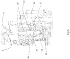
figure 5 est une vue partielle, en perspective, illustrant le raccordement électrique d'un auxiliaire à un disjoncteur au moyen du dispositif de raccordement selon l'invention, et - La
figure 6 est une vue partielle en perspective illustrant seulement une partie de la borne comportant la cage, les deux lames ressort et la plage de raccordement.
- The
figure 1 is a partial plan view of an electrical protection apparatus equipped with a connection device according to a particular preferred embodiment of the invention, said device being in the closed position allowing the insertion of two conductors, - The
figure 2 is a view similar to the previous figure, the connection device being in the open position allowing the withdrawal of the conductors, - The
figure 3 is a view similar to the previous one, the connection device being in the open position, two conductors having been introduced under the connection areas of the apparatus, - The
figure 4 is a view similar to thefigure 3 , the connecting device having been brought into closed position after the conductors have been put in place, - The
figure 5 is a partial view, in perspective, illustrating the electrical connection of an auxiliary to a circuit breaker by means of the connecting device according to the invention, and - The
figure 6 is a partial perspective view illustrating only a portion of the terminal comprising the cage, the two leaf spring and the connection pad.
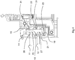
Sur les figures, on voit un appareil de protection et/ou de distribution électrique, notamment un disjoncteur modulaire D, destiné à être fixé sur un support de montage tel un rail R. Cet appareil est logé dans un boîtier B de forme sensiblement parallélépipédique comportant une face avant 1 comportant un nez N à travers lequel débouche une manette M d'actionnement de l'appareil, une face arrière 2 par laquelle l'appareil est monté sur le rail R, deux faces principales 3,4 (
Ainsi, les conducteurs 34 internes à l'appareil débouchent dans des logements 16,17 prévus dans le boîtier de l'appareil et sont accessibles par des orifices 9,10 dans lesquels peuvent être insérés des conducteurs externes 11,12. Ces logements comprennent des moyens de raccordement, permettant le serrage des câbles, souples ou rigides, ou autres, afin de les maintenir en contact avec une partie des conducteurs internes de l'appareil pour finaliser l'installation électrique. Or, il arrive qu'une même borne d'un appareil électrique nécessite d'être raccordée électriquement à deux conducteurs, par exemple dans le cas où le disjoncteur nécessite d'être relié électriquement en aval d'un côté, à un auxiliaire différentiel, et de l'autre côté, à un autre auxiliaire du type contacteur précablé.Thus, the
Le dispositif de raccordement selon cette réalisation préférée décrite ici de l'invention permet de réaliser cette double connexion (ou déconnexion) et comporte une pièce formant étrier 13 montée coulissante par rapport au boîtier de l'appareil et apte à être déplacée en translation par l'intermédiaire d'un moyen d'actionnement comportant un levier 14 rotatif à came 15. Cette came en position ouverte, est apte à maintenir l'étrier en position ouverte grâce à un système de point mort. Ainsi, il est possible d'actionner les deux cames de deux bornes juxtaposées et de maintenir les deux étriers en position ouverte. Cet étrier 13 comporte également deux logements 7,8 destinés à recevoir respectivement deux conducteurs, lesdits logements étant alignés suivant une direction s'étendant sensiblement perpendiculairement au plan P de fixation de l'appareil. A l'intérieur de chacun de ces logements 7,8 est placée une lame ressort 18,19 sensiblement en forme de S, chaque lame ressort étant en appui par l'une 20,21 de ses parties d'extrémité dite première, sur une partie fixe dite seconde 24,31 de la plage de raccordement, et par sa partie d'extrémité opposée 22,23, dite seconde, sur une partie fixe dite première 24,31 de la plage de raccordement de l'appareil.The connecting device according to this preferred embodiment described herein of the invention allows for this double connection (or disconnection) and comprises a stirrup-
A cet effet, l'étrier 13 comporte en regard de chacune des lame-ressorts, une échancrure 25,26 destinée à permettre la création d'une portion 27,28 repliée vers l'intérieur de l'appareil, cette portion étant destinée à venir en appui sur la partie d'extrémité dite première 20,21 de la lame ressort correspondante, de manière à permettre la compression de la lame ressort par l'étrier.For this purpose, the
Cet étrier 13 est formé d'une base 29 coopérant avec la came 15 du levier 14 et de deux flasques 30 s'étendant à partir de la base, chaque flasque 30 comportant la première échancrure précitée 25 située sur le bord libre 32 situé à l'extrémité du flasque et une seconde échancrure 26 située sur l'un 33 des bords latéraux du flasque sensiblement au milieu de sa longueur.This
Chacune des lame-ressorts est placée et dimensionnée à l'intérieur de l'appareil par rapport à l'orifice d'introduction du conducteur correspondant et par rapport à l'étrier, de telle manière que lorsque le levier 14 à came 15 est en position ouverte tel qu'illustré sur les
Ainsi, en fonctionnement, lorsque le levier 14 à came 15 est en position fermée tel qu'illustré sur les
Lors du passage du levier de la position ouverte à la position fermée, la came libère la pression sur les lame-ressorts, lesquelles repoussent l'étrier vers le haut, c'est-à-dire vers le levier.When the lever moves from the open position to the closed position, the cam releases the pressure on the leaf springs, which push the caliper upward, that is to say toward the lever.
On a donc réalisé selon l'invention un dispositif de raccordement permettant le raccordement électrique à un appareil de protection électrique d'auxiliaires standards comportant des conducteurs rigides destinés à être reliés habituellement aux bornes de l'appareil au moyen d'un système à vis.Thus, according to the invention, a connection device has been made which makes it possible to electrically connect standard auxiliaries with rigid conductors which are usually connected to the terminals of the apparatus by means of a screw system.
Tel que particulièrement illustré sur la
L'invention permet de connecter soit un, soit deux conducteurs, de manière rapide. L'invention permet également de maintenir tous les systèmes élastiques ouverts de manière à pouvoir redémonter l'auxiliaire facilement et rapidement du fait que l'invention permet de retirer tous les conducteurs en même temps. L'invention s'applique avantageusement à tout appareil nécessitant de raccorder des conducteurs de petite section.The invention makes it possible to connect one or two conductors quickly. The invention also makes it possible to keep all the elastic systems open so as to be able to restart the auxiliary easily and quickly because the invention makes it possible to remove all the conductors at the same time. The invention is advantageously applicable to any apparatus requiring the connection of conductors of small section.
L'invention s'applique en particulier à des disjoncteurs ayant au moins deux poles, Par exemple des disjoncteurs tripolaire et tétrapolaire./The invention applies in particular to circuit breakers having at least two poles, for example three-pole and four-pole circuit breakers.
Bien entendu, l'invention n'est pas limitée aux modes de réalisations décrits et illustrés qui n'ont été donnés qu'à titre d'exemple.Of course, the invention is not limited to the embodiments described and illustrated which have been given by way of example.
C'est ainsi que l'invention concerne également un dispositif de raccordement ne comportant qu'un orifice d'introduction, un ressort, etc..., c'est-à-dire adapté pour réaliser le raccordement électrique d'un seul conducteur.Thus, the invention also relates to a connection device comprising only an insertion orifice, a spring, etc ..., that is to say adapted to achieve the electrical connection of a single conductor .
Claims (7)
- Device for electrically connecting at least one electrical lead (11, 12) in a terminal belonging to an electrical appliance (D), said connection device including an element forming a yoke (13), said element including at least one opening (9, 10) intended to receive an electrical lead (11, 12) in such a way that this lead (11, 12) is in electrical contact with one of the connection areas of the appliance, and associated with the or each opening (9, 10), a spring bearing by one of its ends on a so-called first fixed part (24, 31) of the connection area of the appliance and by its other end on a so-called second fixed part (31) of the connection area, in the rest position of the spring, and means (14, 15) for actuating the yoke (13) able to move the latter between a first position in which this yoke (13) compresses the spring by way of a cam (15) in such a way as to allow the removal of the lead (11, 12) from the aforementioned opening (9, 10) of the terminal, and a second position in which the pressure exerted by the yoke (13) on the spring is released, this second position authorizing the introduction of a lead (11, 12), the latter being held elastically in the terminal between the so-called second fixed part (31) of the aforementioned area and said spring, the or each aforementioned spring including a spring leaf (18, 19) bearing in the second position of the yoke (13) by the so-called first (20, 21) of its free end parts, on the aforementioned so-called second fixed part (31) of the area of the appliance, and by its second free end part (22, 23), in the absence of leads in the terminal, on the so-called first fixed part (31, 24) of the area, this first free end part (20, 21) being also intended to be brought to bear elastically on the lead (11, 12) when the latter is introduced into the corresponding opening (9, 10), after the movement of the aforementioned actuating means (14, 15) in the second position, in such a way as to retain this lead (11, 12) inside the terminal, the aforementioned yoke (13) being mounted sliding between the two aforementioned positions with respect to the housing (B) of the appliance, characterized in that the aforementioned actuating means (14, 15) include a lever of cam type, and in that the or each aforementioned spring is formed substantially in the shape of an S or U and interacts with a U-shaped connection area in which it is housed such that, when the lever (14) of cam (15) type is in the open position, access to the openings (9, 10) for introducing the leads (11, 12) inside the yoke (13) is freed, each leaf spring (18, 19) bearing, by the free edge of a so-called first (20, 21) of its end parts, on a portion (27, 28) of the yoke (13), and by the free edge of its opposite so-called second end part (22, 23), on the so-called first fixed part (24, 31) of the corresponding connection area, whereas, when the lever (14) is in the closed position, the leads (11, 12) are then held firmly between the free edge of the first end part (20, 21) of the leaf spring (18, 19) and the so-called second fixed part (31) of the corresponding connection area.
- Connection device according to Claim 1, characterized in that the aforementioned yoke (13) includes two seats (7, 8), each intended to receive a lead (11, 12) and each associated with a spring (18, 19), the activation of the actuating means (14, 15) making it possible to actuate the two springs (18, 19) at the same time.
- Connection device according to Claim 1 or 2, characterized in that the two aforementioned introduction openings (9, 10) are aligned in a direction extending substantially perpendicular to the plane (P) of fixing of the appliance (D) on a mounting stand (R).
- Connection device according to any one of the preceding claims, characterized in that the aforementioned yoke (13) includes a part forming a U and including a base (29) and two washers (30), said washers (30) extending substantially perpendicular to said base (29), said base co-operating with the aforementioned actuating means (14, 15), and each washer (30) including at least one notch (25, 26) allowing the folding towards the inside of the appliance of a part of said washer in such a way that this part constitutes a folded part forming a bearing surface (27, 28) able to co-operate with the aforementioned second end part (22, 23) of the aforementioned spring leaf (18, 19) upon the activation of the actuating means (14, 15).
- Connection device according to Claim 4, characterized in that the aforementioned yoke (13) includes two notches (25, 26) situated respectively on the edge of the free end (32) of the washer and on one (33) of the lateral edges of said washer, in the middle of its length, said notches (25, 26) being intended to form two folded portions (27, 28) intended to co-operate respectively with two so-called second end parts (22, 23) of two spring leaves (18, 19) associated respectively with two openings (9, 10) for introducing a lead (11, 12).
- Electrical connection terminal for an electrical protection appliance, characterized in that it includes a connection device according to any one of the preceding claims.
- Low-voltage electrical protection appliance, characterized in that it includes at least one electrical connection terminal according to Claim 6.
Applications Claiming Priority (1)
| Application Number | Priority Date | Filing Date | Title |
|---|---|---|---|
| FR1358932A FR3010839B1 (en) | 2013-09-17 | 2013-09-17 | DEVICE FOR ELECTRICALLY CONNECTING AT LEAST ONE CONDUCTOR IN A TERMINAL BELONGING TO AN ELECTRICAL APPARATUS |
Publications (2)
| Publication Number | Publication Date |
|---|---|
| EP2849287A1 EP2849287A1 (en) | 2015-03-18 |
| EP2849287B1 true EP2849287B1 (en) | 2019-05-15 |
Family
ID=49578474
Family Applications (1)
| Application Number | Title | Priority Date | Filing Date |
|---|---|---|---|
| EP14171713.2A Active EP2849287B1 (en) | 2013-09-17 | 2014-06-10 | Electric connection device of at least one conductor in a terminal belonging to an electric apparatus |
Country Status (3)
| Country | Link |
|---|---|
| EP (1) | EP2849287B1 (en) |
| CN (1) | CN104465238B (en) |
| FR (1) | FR3010839B1 (en) |
Families Citing this family (6)
| Publication number | Priority date | Publication date | Assignee | Title |
|---|---|---|---|---|
| US9252520B1 (en) * | 2014-12-16 | 2016-02-02 | Schneider Electric USA, Inc. | Stacked spring terminals |
| DE102016115601A1 (en) * | 2016-08-23 | 2018-03-01 | Wago Verwaltungsgesellschaft Mbh | Spring terminal connection |
| CN106816347B (en) * | 2017-03-27 | 2018-10-12 | 浙江中亿豪科技有限公司 | A kind of knockdown breaker |
| CN108987153A (en) * | 2017-06-05 | 2018-12-11 | 绍兴联控光电有限公司 | A kind of intelligent control switch |
| DE102017121543A1 (en) * | 2017-09-18 | 2019-03-21 | Phoenix Contact Gmbh & Co. Kg | Connecting device for connecting an electrical line |
| DE102019106351A1 (en) * | 2019-03-13 | 2020-09-17 | Phoenix Contact Gmbh & Co. Kg | Terminal |
Family Cites Families (7)
| Publication number | Priority date | Publication date | Assignee | Title |
|---|---|---|---|---|
| FR2742751B1 (en) * | 1995-12-22 | 1998-01-30 | Rhone Poulenc Rorer Sa | NOVEL TAXOIDS, THEIR PREPARATION AND THE PHARMACEUTICAL COMPOSITIONS CONTAINING THEM |
| US6254422B1 (en) * | 1997-08-25 | 2001-07-03 | Phoenix Contact Gmbh & Co. | Electronic terminal for use on circuit boards |
| JP2000048874A (en) * | 1998-07-30 | 2000-02-18 | Osada:Kk | Terminal box |
| TR200400978T4 (en) * | 1999-12-21 | 2004-07-21 | Siemens Aktiengesellschaft | Screwless connector |
| WO2002013319A1 (en) * | 2000-08-04 | 2002-02-14 | Omron Corporation | Wire connector |
| DE102005052980B3 (en) * | 2005-11-07 | 2007-04-19 | Siemens Ag | Clamping unit for a series apparatus such as a conductor protection switch |
| DE202008014469U1 (en) * | 2008-10-31 | 2010-03-18 | Weidmüller Interface GmbH & Co. KG | Terminal for connecting conductor ends |
-
2013
- 2013-09-17 FR FR1358932A patent/FR3010839B1/en active Active
-
2014
- 2014-06-10 EP EP14171713.2A patent/EP2849287B1/en active Active
- 2014-09-17 CN CN201410474727.3A patent/CN104465238B/en active Active
Non-Patent Citations (1)
| Title |
|---|
| None * |
Also Published As
| Publication number | Publication date |
|---|---|
| FR3010839A1 (en) | 2015-03-20 |
| CN104465238A (en) | 2015-03-25 |
| FR3010839B1 (en) | 2017-04-21 |
| CN104465238B (en) | 2020-07-10 |
| EP2849287A1 (en) | 2015-03-18 |
Similar Documents
| Publication | Publication Date | Title |
|---|---|---|
| EP2849287B1 (en) | Electric connection device of at least one conductor in a terminal belonging to an electric apparatus | |
| EP1151499B1 (en) | Electric switch appliance and quick-assembly | |
| WO2019239024A1 (en) | Metal clip for electrically connecting a conductive wire to a metal element | |
| EP1916743B1 (en) | Electric device comprising at least one spring connection terminal | |
| FR2968144A1 (en) | INTERLOCKING DEVICE FOR SECURING ACCESS TO THE CABLE BOX OF AN ELECTRIC CELL AND ELECTRIC CELL COMPRISING SUCH A DEVICE | |
| EP3206260A1 (en) | Electrical apparatus having a terminal for connection by pressure with a support clip guiding and limiting the resilient deformation of the contact spring | |
| FR2727801A1 (en) | ELECTRICAL EQUIPMENT WITH MODULAR ELEMENTS | |
| EP2335263B1 (en) | Electric connection device and sliding assembly, in particular for a differential protection unit | |
| EP0772256B1 (en) | Electrical apparatus with connection terminals protected by a diaphragm comprising wings | |
| EP2680379B1 (en) | Assembly of modular electric switchgear apparatuses with device for locking them on a mounting rail | |
| EP3487006B1 (en) | Electrical system comprising an electrical apparatus and an interchangeable connector module | |
| EP0307305A1 (en) | Electric connection device for an electric terminal, circuit breaker equipped therewith and set of constituent parts therefor | |
| EP1805850A1 (en) | Terminal board component and screwless connector | |
| EP3598582B1 (en) | Electrical connection device | |
| FR2748352A1 (en) | CONNECTING BASE FOR TRANSMISSION NETWORK, IN PARTICULAR FOR TELEPHONE OR COMPUTER NETWORK | |
| EP1278224B1 (en) | Electrical terminal arrangement for two, next to each other, rail-mounted electrical devices | |
| EP3975353A1 (en) | Electrical distribution device | |
| FR2936367A1 (en) | ELECTRICAL CONNECTOR | |
| FR2691846A1 (en) | Auto-stripping contact electric current holder - connects power cables using insulated body with electric joining plug having electric contact pins and female receptor to receive connector | |
| FR2750803A1 (en) | Electrical connector for switching module | |
| FR3002088A1 (en) | Electrical contact for socket-outlet for e.g. dwelling, has cell extending according to perpendicular direction with respect to longitudinal axis when part is encased in another part | |
| EP1676349A1 (en) | Electrical connection bar and adapted connection device | |
| FR2900508A1 (en) | Metallic power distribution bus-bar for e.g. circuit-breaker, has connection units between connection terminal and stud, and allowing two configurations in which operating unit is in sides of corresponding main surfaces, respectively | |
| EP2068411A1 (en) | Embedded electrical appliance with quick connection | |
| EP0768728A1 (en) | Electrical terminal block |
Legal Events
| Date | Code | Title | Description |
|---|---|---|---|
| PUAI | Public reference made under article 153(3) epc to a published international application that has entered the european phase |
Free format text: ORIGINAL CODE: 0009012 |
|
| 17P | Request for examination filed |
Effective date: 20140610 |
|
| AK | Designated contracting states |
Kind code of ref document: A1 Designated state(s): AL AT BE BG CH CY CZ DE DK EE ES FI FR GB GR HR HU IE IS IT LI LT LU LV MC MK MT NL NO PL PT RO RS SE SI SK SM TR |
|
| AX | Request for extension of the european patent |
Extension state: BA ME |
|
| R17P | Request for examination filed (corrected) |
Effective date: 20150330 |
|
| RBV | Designated contracting states (corrected) |
Designated state(s): AL AT BE BG CH CY CZ DE DK EE ES FI FR GB GR HR HU IE IS IT LI LT LU LV MC MK MT NL NO PL PT RO RS SE SI SK SM TR |
|
| STAA | Information on the status of an ep patent application or granted ep patent |
Free format text: STATUS: EXAMINATION IS IN PROGRESS |
|
| 17Q | First examination report despatched |
Effective date: 20170721 |
|
| GRAP | Despatch of communication of intention to grant a patent |
Free format text: ORIGINAL CODE: EPIDOSNIGR1 |
|
| STAA | Information on the status of an ep patent application or granted ep patent |
Free format text: STATUS: GRANT OF PATENT IS INTENDED |
|
| INTG | Intention to grant announced |
Effective date: 20181211 |
|
| GRAS | Grant fee paid |
Free format text: ORIGINAL CODE: EPIDOSNIGR3 |
|
| GRAA | (expected) grant |
Free format text: ORIGINAL CODE: 0009210 |
|
| STAA | Information on the status of an ep patent application or granted ep patent |
Free format text: STATUS: THE PATENT HAS BEEN GRANTED |
|
| AK | Designated contracting states |
Kind code of ref document: B1 Designated state(s): AL AT BE BG CH CY CZ DE DK EE ES FI FR GB GR HR HU IE IS IT LI LT LU LV MC MK MT NL NO PL PT RO RS SE SI SK SM TR |
|
| REG | Reference to a national code |
Ref country code: CH Ref legal event code: EP |
|
| REG | Reference to a national code |
Ref country code: DE Ref legal event code: R096 Ref document number: 602014046701 Country of ref document: DE |
|
| REG | Reference to a national code |
Ref country code: IE Ref legal event code: FG4D Free format text: LANGUAGE OF EP DOCUMENT: FRENCH |
|
| REG | Reference to a national code |
Ref country code: NL Ref legal event code: MP Effective date: 20190515 |
|
| REG | Reference to a national code |
Ref country code: LT Ref legal event code: MG4D |
|
| PG25 | Lapsed in a contracting state [announced via postgrant information from national office to epo] |
Ref country code: ES Free format text: LAPSE BECAUSE OF FAILURE TO SUBMIT A TRANSLATION OF THE DESCRIPTION OR TO PAY THE FEE WITHIN THE PRESCRIBED TIME-LIMIT Effective date: 20190515 Ref country code: HR Free format text: LAPSE BECAUSE OF FAILURE TO SUBMIT A TRANSLATION OF THE DESCRIPTION OR TO PAY THE FEE WITHIN THE PRESCRIBED TIME-LIMIT Effective date: 20190515 Ref country code: AL Free format text: LAPSE BECAUSE OF FAILURE TO SUBMIT A TRANSLATION OF THE DESCRIPTION OR TO PAY THE FEE WITHIN THE PRESCRIBED TIME-LIMIT Effective date: 20190515 Ref country code: NO Free format text: LAPSE BECAUSE OF FAILURE TO SUBMIT A TRANSLATION OF THE DESCRIPTION OR TO PAY THE FEE WITHIN THE PRESCRIBED TIME-LIMIT Effective date: 20190815 Ref country code: PT Free format text: LAPSE BECAUSE OF FAILURE TO SUBMIT A TRANSLATION OF THE DESCRIPTION OR TO PAY THE FEE WITHIN THE PRESCRIBED TIME-LIMIT Effective date: 20190915 Ref country code: SE Free format text: LAPSE BECAUSE OF FAILURE TO SUBMIT A TRANSLATION OF THE DESCRIPTION OR TO PAY THE FEE WITHIN THE PRESCRIBED TIME-LIMIT Effective date: 20190515 Ref country code: FI Free format text: LAPSE BECAUSE OF FAILURE TO SUBMIT A TRANSLATION OF THE DESCRIPTION OR TO PAY THE FEE WITHIN THE PRESCRIBED TIME-LIMIT Effective date: 20190515 Ref country code: LT Free format text: LAPSE BECAUSE OF FAILURE TO SUBMIT A TRANSLATION OF THE DESCRIPTION OR TO PAY THE FEE WITHIN THE PRESCRIBED TIME-LIMIT Effective date: 20190515 Ref country code: NL Free format text: LAPSE BECAUSE OF FAILURE TO SUBMIT A TRANSLATION OF THE DESCRIPTION OR TO PAY THE FEE WITHIN THE PRESCRIBED TIME-LIMIT Effective date: 20190515 |
|
| PG25 | Lapsed in a contracting state [announced via postgrant information from national office to epo] |
Ref country code: RS Free format text: LAPSE BECAUSE OF FAILURE TO SUBMIT A TRANSLATION OF THE DESCRIPTION OR TO PAY THE FEE WITHIN THE PRESCRIBED TIME-LIMIT Effective date: 20190515 Ref country code: BG Free format text: LAPSE BECAUSE OF FAILURE TO SUBMIT A TRANSLATION OF THE DESCRIPTION OR TO PAY THE FEE WITHIN THE PRESCRIBED TIME-LIMIT Effective date: 20190815 Ref country code: LV Free format text: LAPSE BECAUSE OF FAILURE TO SUBMIT A TRANSLATION OF THE DESCRIPTION OR TO PAY THE FEE WITHIN THE PRESCRIBED TIME-LIMIT Effective date: 20190515 Ref country code: GR Free format text: LAPSE BECAUSE OF FAILURE TO SUBMIT A TRANSLATION OF THE DESCRIPTION OR TO PAY THE FEE WITHIN THE PRESCRIBED TIME-LIMIT Effective date: 20190816 |
|
| REG | Reference to a national code |
Ref country code: AT Ref legal event code: MK05 Ref document number: 1134513 Country of ref document: AT Kind code of ref document: T Effective date: 20190515 |
|
| PG25 | Lapsed in a contracting state [announced via postgrant information from national office to epo] |
Ref country code: AT Free format text: LAPSE BECAUSE OF FAILURE TO SUBMIT A TRANSLATION OF THE DESCRIPTION OR TO PAY THE FEE WITHIN THE PRESCRIBED TIME-LIMIT Effective date: 20190515 Ref country code: EE Free format text: LAPSE BECAUSE OF FAILURE TO SUBMIT A TRANSLATION OF THE DESCRIPTION OR TO PAY THE FEE WITHIN THE PRESCRIBED TIME-LIMIT Effective date: 20190515 Ref country code: DK Free format text: LAPSE BECAUSE OF FAILURE TO SUBMIT A TRANSLATION OF THE DESCRIPTION OR TO PAY THE FEE WITHIN THE PRESCRIBED TIME-LIMIT Effective date: 20190515 Ref country code: RO Free format text: LAPSE BECAUSE OF FAILURE TO SUBMIT A TRANSLATION OF THE DESCRIPTION OR TO PAY THE FEE WITHIN THE PRESCRIBED TIME-LIMIT Effective date: 20190515 Ref country code: CZ Free format text: LAPSE BECAUSE OF FAILURE TO SUBMIT A TRANSLATION OF THE DESCRIPTION OR TO PAY THE FEE WITHIN THE PRESCRIBED TIME-LIMIT Effective date: 20190515 Ref country code: SK Free format text: LAPSE BECAUSE OF FAILURE TO SUBMIT A TRANSLATION OF THE DESCRIPTION OR TO PAY THE FEE WITHIN THE PRESCRIBED TIME-LIMIT Effective date: 20190515 |
|
| REG | Reference to a national code |
Ref country code: CH Ref legal event code: PL |
|
| REG | Reference to a national code |
Ref country code: DE Ref legal event code: R097 Ref document number: 602014046701 Country of ref document: DE |
|
| PG25 | Lapsed in a contracting state [announced via postgrant information from national office to epo] |
Ref country code: MC Free format text: LAPSE BECAUSE OF FAILURE TO SUBMIT A TRANSLATION OF THE DESCRIPTION OR TO PAY THE FEE WITHIN THE PRESCRIBED TIME-LIMIT Effective date: 20190515 Ref country code: SM Free format text: LAPSE BECAUSE OF FAILURE TO SUBMIT A TRANSLATION OF THE DESCRIPTION OR TO PAY THE FEE WITHIN THE PRESCRIBED TIME-LIMIT Effective date: 20190515 |
|
| PLBE | No opposition filed within time limit |
Free format text: ORIGINAL CODE: 0009261 |
|
| STAA | Information on the status of an ep patent application or granted ep patent |
Free format text: STATUS: NO OPPOSITION FILED WITHIN TIME LIMIT |
|
| REG | Reference to a national code |
Ref country code: BE Ref legal event code: MM Effective date: 20190630 |
|
| PG25 | Lapsed in a contracting state [announced via postgrant information from national office to epo] |
Ref country code: TR Free format text: LAPSE BECAUSE OF FAILURE TO SUBMIT A TRANSLATION OF THE DESCRIPTION OR TO PAY THE FEE WITHIN THE PRESCRIBED TIME-LIMIT Effective date: 20190515 |
|
| 26N | No opposition filed |
Effective date: 20200218 |
|
| GBPC | Gb: european patent ceased through non-payment of renewal fee |
Effective date: 20190815 |
|
| PG25 | Lapsed in a contracting state [announced via postgrant information from national office to epo] |
Ref country code: PL Free format text: LAPSE BECAUSE OF FAILURE TO SUBMIT A TRANSLATION OF THE DESCRIPTION OR TO PAY THE FEE WITHIN THE PRESCRIBED TIME-LIMIT Effective date: 20190515 Ref country code: IE Free format text: LAPSE BECAUSE OF NON-PAYMENT OF DUE FEES Effective date: 20190610 |
|
| PG25 | Lapsed in a contracting state [announced via postgrant information from national office to epo] |
Ref country code: LU Free format text: LAPSE BECAUSE OF NON-PAYMENT OF DUE FEES Effective date: 20190610 Ref country code: LI Free format text: LAPSE BECAUSE OF NON-PAYMENT OF DUE FEES Effective date: 20190630 Ref country code: CH Free format text: LAPSE BECAUSE OF NON-PAYMENT OF DUE FEES Effective date: 20190630 Ref country code: SI Free format text: LAPSE BECAUSE OF FAILURE TO SUBMIT A TRANSLATION OF THE DESCRIPTION OR TO PAY THE FEE WITHIN THE PRESCRIBED TIME-LIMIT Effective date: 20190515 Ref country code: BE Free format text: LAPSE BECAUSE OF NON-PAYMENT OF DUE FEES Effective date: 20190630 |
|
| PG25 | Lapsed in a contracting state [announced via postgrant information from national office to epo] |
Ref country code: GB Free format text: LAPSE BECAUSE OF NON-PAYMENT OF DUE FEES Effective date: 20190815 |
|
| PG25 | Lapsed in a contracting state [announced via postgrant information from national office to epo] |
Ref country code: CY Free format text: LAPSE BECAUSE OF FAILURE TO SUBMIT A TRANSLATION OF THE DESCRIPTION OR TO PAY THE FEE WITHIN THE PRESCRIBED TIME-LIMIT Effective date: 20190515 |
|
| PG25 | Lapsed in a contracting state [announced via postgrant information from national office to epo] |
Ref country code: IS Free format text: LAPSE BECAUSE OF FAILURE TO SUBMIT A TRANSLATION OF THE DESCRIPTION OR TO PAY THE FEE WITHIN THE PRESCRIBED TIME-LIMIT Effective date: 20190915 |
|
| PG25 | Lapsed in a contracting state [announced via postgrant information from national office to epo] |
Ref country code: MT Free format text: LAPSE BECAUSE OF FAILURE TO SUBMIT A TRANSLATION OF THE DESCRIPTION OR TO PAY THE FEE WITHIN THE PRESCRIBED TIME-LIMIT Effective date: 20190515 Ref country code: HU Free format text: LAPSE BECAUSE OF FAILURE TO SUBMIT A TRANSLATION OF THE DESCRIPTION OR TO PAY THE FEE WITHIN THE PRESCRIBED TIME-LIMIT; INVALID AB INITIO Effective date: 20140610 |
|
| PG25 | Lapsed in a contracting state [announced via postgrant information from national office to epo] |
Ref country code: MK Free format text: LAPSE BECAUSE OF FAILURE TO SUBMIT A TRANSLATION OF THE DESCRIPTION OR TO PAY THE FEE WITHIN THE PRESCRIBED TIME-LIMIT Effective date: 20190515 |
|
| PGFP | Annual fee paid to national office [announced via postgrant information from national office to epo] |
Ref country code: FR Payment date: 20230622 Year of fee payment: 10 Ref country code: DE Payment date: 20230627 Year of fee payment: 10 |
|
| PGFP | Annual fee paid to national office [announced via postgrant information from national office to epo] |
Ref country code: IT Payment date: 20230620 Year of fee payment: 10 |