EP2849287B1 - Elektrische Anschlussvorrichtung mit mindestens einem Leiter in einer Klemme, die zu einem elektrischen Gerät gehört - Google Patents
Elektrische Anschlussvorrichtung mit mindestens einem Leiter in einer Klemme, die zu einem elektrischen Gerät gehört Download PDFInfo
- Publication number
- EP2849287B1 EP2849287B1 EP14171713.2A EP14171713A EP2849287B1 EP 2849287 B1 EP2849287 B1 EP 2849287B1 EP 14171713 A EP14171713 A EP 14171713A EP 2849287 B1 EP2849287 B1 EP 2849287B1
- Authority
- EP
- European Patent Office
- Prior art keywords
- aforementioned
- spring
- called
- yoke
- connection
- Prior art date
- Legal status (The legal status is an assumption and is not a legal conclusion. Google has not performed a legal analysis and makes no representation as to the accuracy of the status listed.)
- Active
Links
- 239000004020 conductor Substances 0.000 title description 41
- 230000004913 activation Effects 0.000 claims description 3
- 238000003780 insertion Methods 0.000 description 7
- 230000037431 insertion Effects 0.000 description 7
- 230000003213 activating effect Effects 0.000 description 1
- 230000006835 compression Effects 0.000 description 1
- 238000007906 compression Methods 0.000 description 1
- 230000008878 coupling Effects 0.000 description 1
- 238000010168 coupling process Methods 0.000 description 1
- 238000005859 coupling reaction Methods 0.000 description 1
- 238000006073 displacement reaction Methods 0.000 description 1
- 238000010616 electrical installation Methods 0.000 description 1
- 238000007373 indentation Methods 0.000 description 1
- 238000000034 method Methods 0.000 description 1
- 230000007935 neutral effect Effects 0.000 description 1
- 230000000717 retained effect Effects 0.000 description 1
Images


Classifications
-
- H—ELECTRICITY
- H01—ELECTRIC ELEMENTS
- H01R—ELECTRICALLY-CONDUCTIVE CONNECTIONS; STRUCTURAL ASSOCIATIONS OF A PLURALITY OF MUTUALLY-INSULATED ELECTRICAL CONNECTING ELEMENTS; COUPLING DEVICES; CURRENT COLLECTORS
- H01R4/00—Electrically-conductive connections between two or more conductive members in direct contact, i.e. touching one another; Means for effecting or maintaining such contact; Electrically-conductive connections having two or more spaced connecting locations for conductors and using contact members penetrating insulation
- H01R4/28—Clamped connections, spring connections
- H01R4/48—Clamped connections, spring connections utilising a spring, clip, or other resilient member
- H01R4/4809—Clamped connections, spring connections utilising a spring, clip, or other resilient member using a leaf spring to bias the conductor toward the busbar
- H01R4/4828—Spring-activating arrangements mounted on or integrally formed with the spring housing
- H01R4/48365—Spring-activating arrangements mounted on or integrally formed with the spring housing with integral release means
Definitions
- the present invention relates to a device for electrical connection of at least one electrical conductor in a terminal belonging to an electrical appliance, said connecting device comprising a stirrup-shaped part, said part comprising at least one orifice intended to receive an electrical conductor of such so that this conductor is in electrical contact with one of the connection areas of the device, and associated with the or each orifice, a spring bearing by one of its ends on a so-called fixed first portion of the range of connecting the device and at its other end to a so-called second fixed portion of the connection pad, at least in the rest position of the spring, and means for actuating the stirrup adapted to move the latter between a first position wherein said caliper compresses the spring so as to allow removal of the conductor from the aforementioned hole of the terminal, and a second position in which the pressure exerted by the stirrup on the spring is released, this second position allowing the introduction of a conductor, the latter being elastically retained in the terminal between the so-called second fixed portion of the connection range of
- connection terminals Three types of connection terminals are known at the present time, namely the screw-type connection terminals, the quick-connect type connection terminals and the self-stripping terminals.
- the screw terminals allow the connection of one or two wires in the same terminal, but do not constitute a means of quick connection.
- the quick-type connection terminals use one or more springs to lock the wire in the connected position.
- Several methods can be used to release the conductor by compressing the spring. These terminals use to compress the spring is a screwdriver, a sliding lever, a rotary lever cam or others, etc ....
- the document US2011 / 0207361 discloses an electrical connection device according to the preamble of claim 1, using a connection terminal equipped with a cam to compress the spring.
- connection terminals of the fast type have the disadvantage that they do not allow two conductors to be connected at the same time, and that it is then necessary to use two separate terminals which must be actuated separately.
- these quick-connect type terminals are arranged side by side and have their own conductor release devices.
- the present invention solves these disadvantages and proposes a fast type electrical connection device of simple design, compatible with auxiliary devices usually connected by means of screws.
- Another object of the invention is to provide a connection device that can be used to quickly connect or disconnect either one or two or more than two conductors quickly and simultaneously.
- the invention also relates to a connection terminal comprising such a device, and an electrical protection device comprising at least one such terminal.
- the present invention relates to a device for electrical connection of at least one electrical conductor in a terminal belonging to an electrical protection device, as defined in claim 1.
- the or each said spring comprises a spring blade supported by one of said first of its free end portions, on the so-called first fixed portion of the connection area of the apparatus, and by its second free end portion, the absence of conductors in the terminal, on the so-called second fixed portion of the connection pad, this second free end portion being also intended to be brought into elastic support on the conductor when it is inserted into the orifice corresponding, after the displacement of the aforementioned actuating means in the second position, so as to retain the conductor inside the terminal.
- the aforesaid caliper comprises two housings each for receiving a conductor and each associated with a spring, the activation of the actuating means for actuating the two springs at the same time.
- connection is made of one or two conductors at the same time, quickly. It is thus possible to keep all the elastic systems open so as to be able to restart the auxiliary, which has at least two conductors, easily and quickly, because it is possible to remove all the conductors at the same time.
- the two aforementioned insertion orifices are aligned in a direction extending substantially perpendicular to the attachment plane of the apparatus on a mounting bracket.
- This arrangement is particularly suitable for connecting an auxiliary device such as a differential protection device.
- the aforesaid bracket is slidably mounted between the two aforementioned positions relative to the housing of the apparatus.
- the aforementioned actuating means comprise a cam lever.
- said stirrup has a portion forming a U and comprising a base and two flanges, said flanges extending substantially perpendicularly to said base, said base cooperating with said actuating means, and each flange comprising at least one notch allowing the inward folding of the apparatus of a portion of said flange so that this portion constitutes a folded portion forming a bearing surface capable of cooperating with the second end portion of said blade aforementioned spring when activating the actuating means.
- the above-mentioned stirrup has two notches located respectively on the free end edge of the flange and on one of the lateral edges of said flange, in the middle of its length, said notches being intended to form two folded portions. intended to cooperate respectively with two so-called second end portions of two spring blades respectively associated with two insertion holes of a conductor.
- the or each spring is substantially shaped in S or U.
- the present invention also relates to an electrical connection terminal for an electrical protection device comprising a connection device comprising the previously mentioned features taken alone or in combination.
- the present invention further relates to a low voltage electrical protection device comprising at least one terminal having the above-mentioned characteristics taken alone or in combination.
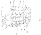
- an electrical protection and / or distribution apparatus in particular a modular circuit breaker D, intended to be fixed on a mounting support such as a rail R.
- This apparatus is housed in a substantially parallelepiped-shaped housing B comprising a front face 1 having a nose N through which opens an operating lever M of the device, a rear face 2 through which the device is mounted on the rail R, two main faces 3,4 ( figure 5 ) by which the apparatus can be attached to other devices of the same type also mounted on the same support, and two side faces 5 usually positioned above and below the apparatus in a mounting cabinet and provided with means allowing the unit to be connected to a distribution network or to other electrical devices.
- the conductors 34 internal to the device open into housings 16,17 provided in the housing of the device and are accessible through orifices 9,10 in which can be inserted external conductors 11,12.
- These housings include connection means, allowing the clamping of flexible or rigid cables, or other, to keep them in contact with a portion of the internal conductors of the device to complete the electrical installation.
- connection means allowing the clamping of flexible or rigid cables, or other, to keep them in contact with a portion of the internal conductors of the device to complete the electrical installation.
- the same terminal of an electrical apparatus requires to be electrically connected to two conductors, for example in the case where the circuit breaker needs to be electrically connected downstream on one side, to a differential auxiliary, and on the other side, another auxiliary of the contactor type pre-wired.
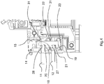
- the connecting device allows for this double connection (or disconnection) and comprises a stirrup-shaped part 13 slidably mounted relative to the housing of the device and able to be displaced in translation by the intermediate of an actuating means comprising a rotary lever 14 to cam 15.
- This cam in the open position is able to maintain the stirrup in the open position through a neutral system.
- This stirrup 13 also comprises two housings 7, 8 intended to receive respectively two conductors, said housings being aligned in a direction extending substantially perpendicularly to the plane P of fixing the apparatus.
- each leaf spring being supported by a 20,21 of its end portions said first, on a fixed part said second 24,31 of the range of connection, and its opposite end portion 22,23, said second, on a so-called first fixed portion 24,31 of the connection range of the device.
- the stirrup 13 comprises opposite each of the leaf springs, a notch 25,26 intended to allow the creation of a portion 27,28 folded towards the inside of the apparatus, this portion being intended for come to bear on the so-called first end portion 20,21 of the corresponding leaf spring, so as to allow the compression of the leaf spring by the stirrup.
- This stirrup 13 is formed of a base 29 cooperating with the cam 15 of the lever 14 and two flanges 30 extending from the base, each flange 30 having the aforesaid first indentation 25 located on the free edge 32 located at the bottom. end of the flange and a second notch 26 located on one of the 33 side edges of the flange substantially in the middle of its length.
- Each of the leaf springs is placed and dimensioned inside the apparatus with respect to the corresponding conductor insertion hole and with respect to the yoke, so that when the cam lever 15 is in position. open position as illustrated in the figures 2 , 3 and 5 the access to the driver introduction ports 9, 10 and to the housings 7, 8 inside the stirrup 13 is released and thus allows either the introduction of the conductors or the withdrawal of said conductors, while when the lever 14 is in the closed position, as illustrated on the figures 1 and 4 these orifices are partially closed off by the first parts 20, 21 of the leaf springs, but nevertheless allow the introduction of the conductors until the conductors are brought into contact with the corresponding ranges of the apparatus, the said conductors being then held firmly between the first end portion 20,21 of the spring blade 18,19 and a so-called second fixed portion 24,31 of the corresponding connection pad.
- connection device which makes it possible to electrically connect standard auxiliaries with rigid conductors which are usually connected to the terminals of the apparatus by means of a screw system.
- connection device advantageously makes it possible to connect a differential auxiliary to a circuit breaker.
- the invention makes it possible to connect one or two conductors quickly.
- the invention also makes it possible to keep all the elastic systems open so as to be able to restart the auxiliary easily and quickly because the invention makes it possible to remove all the conductors at the same time.
- the invention is advantageously applicable to any apparatus requiring the connection of conductors of small section.
- the invention applies in particular to circuit breakers having at least two poles, for example three-pole and four-pole circuit breakers.
- connection device comprising only an insertion orifice, a spring, etc ..., that is to say adapted to achieve the electrical connection of a single conductor .
Claims (7)
- Elektrische Anschlussvorrichtung mindestens eines elektrischen Leiters (11, 12) in einer zu einem elektrischen Gerät (D) gehörenden Klemme, wobei die Anschlussvorrichtung ein einen Bügel (13) formendes Bauteil aufweist, wobei das Bauteil mindestens eine Öffnung (9, 10), die dazu bestimmt ist, einen elektrischen Leiter (11, 12) so aufzunehmen, dass dieser Leiter (11, 12) mit einem der Anschlussbereiche des Geräts in elektrischem Kontakt ist, und der oder jeder Öffnung (9, 10) zugeordnet ist, eine Feder in Auflage durch eines ihrer Enden auf einem so genannten ersten ortsfesten Teil (24, 31) des Anschlussbereichs des Geräts und durch ihr anderes Ende auf einem so genannten zweiten ortsfesten Teil (31) des Anschlussbereichs in Ruhestellung der Feder, und Betätigungseinrichtungen (14, 15) des Bügels (13) aufweist, die diesen letzteren zwischen einer ersten Stellung, in der dieser Bügel (13) die Feder mittels einer Nocke (15) zusammendrückt, um das Entfernen des Leiters (11, 12) aus der erwähnten Öffnung (9, 10) der Klemme zu ermöglichen, und einer zweiten Stellung verschieben können, in der der vom Bügel (13) auf die Feder ausgeübte Druck gelöst wird, wobei diese zweite Stellung die Einführung eines Leiters (11, 12) erlaubt, wobei dieser letztere in der Klemme zwischen dem so genannten zweiten ortsfesten Teil (31) des erwähnten Bereichs und der Feder elastisch gehalten wird, wobei die oder jede erwähnte Feder eine Blattfeder (18,19) aufweist, die in der zweiten Stellung des Bügels (13) durch einen erster (20, 21) genannten ihrer freien Endteile auf dem erwähnten, zweiter genannten ortsfesten Teil (31) des Bereichs des Geräts, und durch ihren zweiten freien Endteil (22, 23), in Abwesenheit von Leitern in der Klemme, auf dem erster genannten ortsfesten Teil (31, 24) des Bereichs aufliegt, wobei dieser erste freie Endteil (20, 21) ebenfalls dazu bestimmt ist, in elastische Auflage auf den Leiter (11, 12) gebracht zu werden, wenn dieser in die entsprechende Öffnung (9, 10) eingeführt wird, nach der Verschiebung der erwähnten Betätigungseinrichtungen (14, 15) in die zweite Stellung, um diesen Leiter (11,12) im Inneren der Klemme zu halten, wobei der erwähnte Bügel (13) zwischen den zwei erwähnten Stellungen bezüglich des Gehäuses (B) des Geräts gleitend montiert ist, dadurch gekennzeichnet, dass die erwähnten Betätigungseinrichtungen (14, 15) einen Nockenhebel aufweisen, und dass die oder jede erwähnte Feder im Wesentlichen eine S- oder U-Form hat und mit einem U-förmigen Anschlussbereich zusammenwirkt, in dem sie so untergebracht ist, dass, wenn der Hebel (14) mit Nocke (15) in offener Stellung ist, der Zugang zu den Einführöffnungen (9, 10) der Leiter (11, 12) ins Innere des Bügels (13) freigegeben wird, wobei jede Blattfeder (18, 19) durch den freien Rand eines (20, 21) erster genannten ihrer Endteile auf einem Abschnitt (27, 28) des Bügels (13), und durch den freien Rand ihres zweiter genannten gegenüberliegenden Teils (22, 23) auf dem erster genannten ortsfesten Teil (24, 31) des entsprechenden Anschlussbereichs in Auflage ist, während, wenn der Hebel (14) in geschlossener Stellung ist, die Leiter (11, 12) dann fest zwischen dem freien Rand des ersten Endteils (20, 21) der Blattfeder (18, 19) und dem zweiter genannten ortsfesten Teil (31) des entsprechenden Anschlussbereichs gehalten werden.
- Anschlussvorrichtung nach Anspruch 1, dadurch gekennzeichnet, dass der erwähnte Bügel (13) zwei Aufnahmen (7, 8) aufweist, die dazu bestimmt sind, je einen Leiter (11, 12) aufzunehmen, und je einer Feder (18, 19) zugeordnet sind, wobei die Aktivierung der Betätigungseinrichtungen (14, 15) es ermöglicht, die zwei Federn (18,19) gleichzeitig zu betätigen.
- Anschlussvorrichtung nach Anspruch 1 oder 2, dadurch gekennzeichnet, dass die zwei erwähnten Einführöffnungen (9, 10) gemäß einer Richtung ausgerichtet sind, die sich im Wesentlichen lotrecht zur Befestigungsebene (P) des Geräts (D) auf einem Montageträger (R) erstreckt.
- Anschlussvorrichtung nach einem der vorhergehenden Ansprüche, dadurch gekennzeichnet, dass der erwähnte Bügel (13) einen ein U formenden und eine Basis (29) und zwei Flansche (30) aufweisenden Teil aufweist, wobei die Flansche (30) sich im Wesentlichen lotrecht zur Basis (29) erstrecken, wobei die Basis mit den erwähnten Betätigungseinrichtungen (14, 15) zusammenwirkt, und jeder Flansch (30) mindestens eine Aussparung (25, 26) aufweist, die das Umbiegen eines Teils des Flanschs zur Innenseite des Geräts erlaubt, damit dieser Teil einen umgebogenen Teil bildet, der eine Auflagefläche (27, 28) formt, die mit dem erwähnten zweiten Endteil (22, 23) der erwähnten Blattfeder (18, 19) bei der Aktivierung des Betätigungseinrichtungen (14, 15) zusammenwirken kann.
- Anschlussvorrichtung nach Anspruch 4, dadurch gekennzeichnet, dass der erwähnte Bügel (13) zwei Aussparungen (25, 26) aufweist, die sich auf dem freien Endrand (32) des Flanschs bzw. auf einem (33) der Seitenränder des Flanschs in der Mitte seiner Länge befinden, wobei die Aussparungen (25, 26) dazu bestimmt sind, zwei umgebogene Abschnitte (27, 28) zu formen, die dazu bestimmt sind, mit zwei zweite genannten Endteilen (22, 23) von zwei Blattfedern (18, 19) zusammenzuwirken, die je zwei Einführöffnungen (9, 10) eines Leiters (11, 12) zugeordnet sind.
- Elektrische Anschlussklemme für ein elektrisches Schutzgerät, dadurch gekennzeichnet, dass sie eine Anschlussvorrichtung nach einem der vorhergehenden Ansprüche aufweist.
- Elektrisches Niederspannungsschutzgerät, dadurch gekennzeichnet, dass es mindestens eine elektrische Anschlussklemme nach Anspruch 6 aufweist.
Applications Claiming Priority (1)
| Application Number | Priority Date | Filing Date | Title |
|---|---|---|---|
| FR1358932A FR3010839B1 (fr) | 2013-09-17 | 2013-09-17 | Dispositif de raccordement electrique d'au moins un conducteur dans une borne appartenant a un appareil electrique |
Publications (2)
| Publication Number | Publication Date |
|---|---|
| EP2849287A1 EP2849287A1 (de) | 2015-03-18 |
| EP2849287B1 true EP2849287B1 (de) | 2019-05-15 |
Family
ID=49578474
Family Applications (1)
| Application Number | Title | Priority Date | Filing Date |
|---|---|---|---|
| EP14171713.2A Active EP2849287B1 (de) | 2013-09-17 | 2014-06-10 | Elektrische Anschlussvorrichtung mit mindestens einem Leiter in einer Klemme, die zu einem elektrischen Gerät gehört |
Country Status (3)
| Country | Link |
|---|---|
| EP (1) | EP2849287B1 (de) |
| CN (1) | CN104465238B (de) |
| FR (1) | FR3010839B1 (de) |
Families Citing this family (6)
| Publication number | Priority date | Publication date | Assignee | Title |
|---|---|---|---|---|
| US9252520B1 (en) * | 2014-12-16 | 2016-02-02 | Schneider Electric USA, Inc. | Stacked spring terminals |
| DE102016115601A1 (de) * | 2016-08-23 | 2018-03-01 | Wago Verwaltungsgesellschaft Mbh | Federkraftklemmanschluss |
| CN106816347B (zh) * | 2017-03-27 | 2018-10-12 | 浙江中亿豪科技有限公司 | 一种组合式的断路器 |
| CN108987153A (zh) * | 2017-06-05 | 2018-12-11 | 绍兴联控光电有限公司 | 一种智能控制开关 |
| DE102017121543A1 (de) * | 2017-09-18 | 2019-03-21 | Phoenix Contact Gmbh & Co. Kg | Anschlusseinrichtung zum Anschließen einer elektrischen Leitung |
| DE102019106351A1 (de) * | 2019-03-13 | 2020-09-17 | Phoenix Contact Gmbh & Co. Kg | Anschlussklemme |
Family Cites Families (7)
| Publication number | Priority date | Publication date | Assignee | Title |
|---|---|---|---|---|
| FR2742751B1 (fr) * | 1995-12-22 | 1998-01-30 | Rhone Poulenc Rorer Sa | Nouveaux taxoides, leur preparation et les compositions pharmaceutiques qui les contiennent |
| US6254422B1 (en) * | 1997-08-25 | 2001-07-03 | Phoenix Contact Gmbh & Co. | Electronic terminal for use on circuit boards |
| JP2000048874A (ja) * | 1998-07-30 | 2000-02-18 | Osada:Kk | 端子台 |
| EP1240687B1 (de) * | 1999-12-21 | 2004-03-17 | Siemens Aktiengesellschaft | Schraubenlose klemme |
| CN1205697C (zh) * | 2000-08-04 | 2005-06-08 | 欧姆龙株式会社 | 电线连接器具 |
| DE102005052980B3 (de) * | 2005-11-07 | 2007-04-19 | Siemens Ag | Klemmvorrichtung für ein Reiheneinbaugerät |
| DE202008014469U1 (de) * | 2008-10-31 | 2010-03-18 | Weidmüller Interface GmbH & Co. KG | Anschlussklemme zum Anschluss von Leiterenden |
-
2013
- 2013-09-17 FR FR1358932A patent/FR3010839B1/fr active Active
-
2014
- 2014-06-10 EP EP14171713.2A patent/EP2849287B1/de active Active
- 2014-09-17 CN CN201410474727.3A patent/CN104465238B/zh active Active
Non-Patent Citations (1)
| Title |
|---|
| None * |
Also Published As
| Publication number | Publication date |
|---|---|
| CN104465238B (zh) | 2020-07-10 |
| FR3010839B1 (fr) | 2017-04-21 |
| EP2849287A1 (de) | 2015-03-18 |
| FR3010839A1 (fr) | 2015-03-20 |
| CN104465238A (zh) | 2015-03-25 |
Similar Documents
| Publication | Publication Date | Title |
|---|---|---|
| EP2849287B1 (de) | Elektrische Anschlussvorrichtung mit mindestens einem Leiter in einer Klemme, die zu einem elektrischen Gerät gehört | |
| EP1151499B1 (de) | Elektrische schalteranordnung | |
| WO2019239024A1 (fr) | Clip metallique de connexion electrique d'un fil conducteur a un element metallique | |
| EP1916743B1 (de) | Elektrisches Gerät, das mindestens eine Federanschlussklemme umfasst | |
| FR2968144A1 (fr) | Dispositif d'interverrouillage destine a securiser l'acces a la boite a cables d'une cellule electrique et cellule electrique comportant un tel dispositif | |
| EP3206260A1 (de) | Elektrisches gerät, das über eine druckverbindungsklemme mit einer halteklammer verfügt, die die elastische verformung der kontaktfeder führt und begrenzt | |
| EP2335263B1 (de) | Elektrische verbindungseinrichtung und schiebebaugruppe, insbesondere für eine differenz-schutzeinheit | |
| EP0772256B1 (de) | Elektrisches Gerät mit Anschlussklemmen, die durch eine Blende mit Flügeln geschützt sind | |
| EP2680379B1 (de) | Kombination aus modularen schaltgeräte mit verriegelungsvorrichtung auf einer montageschiene | |
| EP3487006B1 (de) | Elektrisches system, das ein elektrogerät und ein auswechselbares verbindungsmodul umfasst | |
| EP0307305A1 (de) | Elektrische Verbindungseinrichtung für elektrischen Apparatanschluss, so ausgerüstetes elektrisches Schütz und alle Teile, die dazu gehören | |
| WO2006048530A1 (fr) | Element de bornier et connecteur sans vis | |
| FR2748352A1 (fr) | Socle de branchement pour reseau de transmission, en particulier pour reseau telephonique ou informatique | |
| EP1278224B1 (de) | Elektrische Verbindungsvorrichtung für zwei nebeneinander auf einer Schiene montierte elektrische Geräte | |
| EP3975353A1 (de) | Elektrische stromverteilungsvorrichtung | |
| FR2936367A1 (fr) | Connecteur electrique | |
| FR2691846A1 (fr) | Prise de courant électrique à contact auto-dénudant. | |
| EP2849288B1 (de) | Elektrisches Gerät, das über einen Messkamm mit Strom versorgt wird, und das mit mindestens einer Klemme ausgestattet ist. | |
| FR3002088A1 (fr) | Contact electrique pour prise de courant | |
| EP1676349A1 (de) | Elektrische verbindungsschiene und angepasste verbindungseinrichtung | |
| FR2900508A1 (fr) | Barre omnibus pour repartition electrique | |
| EP3349306B1 (de) | Modular elektrisches gerät | |
| EP2068411A1 (de) | Elektrische Einbau-Ausrüstung mit Schnellanschluss | |
| EP0768728A1 (de) | Elektrische Anschlussleiste | |
| FR3133492A3 (fr) | Système de raccordement d’un appareil électrique modulaire à un coffret de distribution électrique, appareil électrique modulaire, et ensemble comprenant un coffret de distribution électrique et un tel système de raccordement |
Legal Events
| Date | Code | Title | Description |
|---|---|---|---|
| PUAI | Public reference made under article 153(3) epc to a published international application that has entered the european phase |
Free format text: ORIGINAL CODE: 0009012 |
|
| 17P | Request for examination filed |
Effective date: 20140610 |
|
| AK | Designated contracting states |
Kind code of ref document: A1 Designated state(s): AL AT BE BG CH CY CZ DE DK EE ES FI FR GB GR HR HU IE IS IT LI LT LU LV MC MK MT NL NO PL PT RO RS SE SI SK SM TR |
|
| AX | Request for extension of the european patent |
Extension state: BA ME |
|
| R17P | Request for examination filed (corrected) |
Effective date: 20150330 |
|
| RBV | Designated contracting states (corrected) |
Designated state(s): AL AT BE BG CH CY CZ DE DK EE ES FI FR GB GR HR HU IE IS IT LI LT LU LV MC MK MT NL NO PL PT RO RS SE SI SK SM TR |
|
| STAA | Information on the status of an ep patent application or granted ep patent |
Free format text: STATUS: EXAMINATION IS IN PROGRESS |
|
| 17Q | First examination report despatched |
Effective date: 20170721 |
|
| GRAP | Despatch of communication of intention to grant a patent |
Free format text: ORIGINAL CODE: EPIDOSNIGR1 |
|
| STAA | Information on the status of an ep patent application or granted ep patent |
Free format text: STATUS: GRANT OF PATENT IS INTENDED |
|
| INTG | Intention to grant announced |
Effective date: 20181211 |
|
| GRAS | Grant fee paid |
Free format text: ORIGINAL CODE: EPIDOSNIGR3 |
|
| GRAA | (expected) grant |
Free format text: ORIGINAL CODE: 0009210 |
|
| STAA | Information on the status of an ep patent application or granted ep patent |
Free format text: STATUS: THE PATENT HAS BEEN GRANTED |
|
| AK | Designated contracting states |
Kind code of ref document: B1 Designated state(s): AL AT BE BG CH CY CZ DE DK EE ES FI FR GB GR HR HU IE IS IT LI LT LU LV MC MK MT NL NO PL PT RO RS SE SI SK SM TR |
|
| REG | Reference to a national code |
Ref country code: CH Ref legal event code: EP |
|
| REG | Reference to a national code |
Ref country code: DE Ref legal event code: R096 Ref document number: 602014046701 Country of ref document: DE |
|
| REG | Reference to a national code |
Ref country code: IE Ref legal event code: FG4D Free format text: LANGUAGE OF EP DOCUMENT: FRENCH |
|
| REG | Reference to a national code |
Ref country code: NL Ref legal event code: MP Effective date: 20190515 |
|
| REG | Reference to a national code |
Ref country code: LT Ref legal event code: MG4D |
|
| PG25 | Lapsed in a contracting state [announced via postgrant information from national office to epo] |
Ref country code: ES Free format text: LAPSE BECAUSE OF FAILURE TO SUBMIT A TRANSLATION OF THE DESCRIPTION OR TO PAY THE FEE WITHIN THE PRESCRIBED TIME-LIMIT Effective date: 20190515 Ref country code: HR Free format text: LAPSE BECAUSE OF FAILURE TO SUBMIT A TRANSLATION OF THE DESCRIPTION OR TO PAY THE FEE WITHIN THE PRESCRIBED TIME-LIMIT Effective date: 20190515 Ref country code: AL Free format text: LAPSE BECAUSE OF FAILURE TO SUBMIT A TRANSLATION OF THE DESCRIPTION OR TO PAY THE FEE WITHIN THE PRESCRIBED TIME-LIMIT Effective date: 20190515 Ref country code: NO Free format text: LAPSE BECAUSE OF FAILURE TO SUBMIT A TRANSLATION OF THE DESCRIPTION OR TO PAY THE FEE WITHIN THE PRESCRIBED TIME-LIMIT Effective date: 20190815 Ref country code: PT Free format text: LAPSE BECAUSE OF FAILURE TO SUBMIT A TRANSLATION OF THE DESCRIPTION OR TO PAY THE FEE WITHIN THE PRESCRIBED TIME-LIMIT Effective date: 20190915 Ref country code: SE Free format text: LAPSE BECAUSE OF FAILURE TO SUBMIT A TRANSLATION OF THE DESCRIPTION OR TO PAY THE FEE WITHIN THE PRESCRIBED TIME-LIMIT Effective date: 20190515 Ref country code: FI Free format text: LAPSE BECAUSE OF FAILURE TO SUBMIT A TRANSLATION OF THE DESCRIPTION OR TO PAY THE FEE WITHIN THE PRESCRIBED TIME-LIMIT Effective date: 20190515 Ref country code: LT Free format text: LAPSE BECAUSE OF FAILURE TO SUBMIT A TRANSLATION OF THE DESCRIPTION OR TO PAY THE FEE WITHIN THE PRESCRIBED TIME-LIMIT Effective date: 20190515 Ref country code: NL Free format text: LAPSE BECAUSE OF FAILURE TO SUBMIT A TRANSLATION OF THE DESCRIPTION OR TO PAY THE FEE WITHIN THE PRESCRIBED TIME-LIMIT Effective date: 20190515 |
|
| PG25 | Lapsed in a contracting state [announced via postgrant information from national office to epo] |
Ref country code: RS Free format text: LAPSE BECAUSE OF FAILURE TO SUBMIT A TRANSLATION OF THE DESCRIPTION OR TO PAY THE FEE WITHIN THE PRESCRIBED TIME-LIMIT Effective date: 20190515 Ref country code: BG Free format text: LAPSE BECAUSE OF FAILURE TO SUBMIT A TRANSLATION OF THE DESCRIPTION OR TO PAY THE FEE WITHIN THE PRESCRIBED TIME-LIMIT Effective date: 20190815 Ref country code: LV Free format text: LAPSE BECAUSE OF FAILURE TO SUBMIT A TRANSLATION OF THE DESCRIPTION OR TO PAY THE FEE WITHIN THE PRESCRIBED TIME-LIMIT Effective date: 20190515 Ref country code: GR Free format text: LAPSE BECAUSE OF FAILURE TO SUBMIT A TRANSLATION OF THE DESCRIPTION OR TO PAY THE FEE WITHIN THE PRESCRIBED TIME-LIMIT Effective date: 20190816 |
|
| REG | Reference to a national code |
Ref country code: AT Ref legal event code: MK05 Ref document number: 1134513 Country of ref document: AT Kind code of ref document: T Effective date: 20190515 |
|
| PG25 | Lapsed in a contracting state [announced via postgrant information from national office to epo] |
Ref country code: AT Free format text: LAPSE BECAUSE OF FAILURE TO SUBMIT A TRANSLATION OF THE DESCRIPTION OR TO PAY THE FEE WITHIN THE PRESCRIBED TIME-LIMIT Effective date: 20190515 Ref country code: EE Free format text: LAPSE BECAUSE OF FAILURE TO SUBMIT A TRANSLATION OF THE DESCRIPTION OR TO PAY THE FEE WITHIN THE PRESCRIBED TIME-LIMIT Effective date: 20190515 Ref country code: DK Free format text: LAPSE BECAUSE OF FAILURE TO SUBMIT A TRANSLATION OF THE DESCRIPTION OR TO PAY THE FEE WITHIN THE PRESCRIBED TIME-LIMIT Effective date: 20190515 Ref country code: RO Free format text: LAPSE BECAUSE OF FAILURE TO SUBMIT A TRANSLATION OF THE DESCRIPTION OR TO PAY THE FEE WITHIN THE PRESCRIBED TIME-LIMIT Effective date: 20190515 Ref country code: CZ Free format text: LAPSE BECAUSE OF FAILURE TO SUBMIT A TRANSLATION OF THE DESCRIPTION OR TO PAY THE FEE WITHIN THE PRESCRIBED TIME-LIMIT Effective date: 20190515 Ref country code: SK Free format text: LAPSE BECAUSE OF FAILURE TO SUBMIT A TRANSLATION OF THE DESCRIPTION OR TO PAY THE FEE WITHIN THE PRESCRIBED TIME-LIMIT Effective date: 20190515 |
|
| REG | Reference to a national code |
Ref country code: CH Ref legal event code: PL |
|
| REG | Reference to a national code |
Ref country code: DE Ref legal event code: R097 Ref document number: 602014046701 Country of ref document: DE |
|
| PG25 | Lapsed in a contracting state [announced via postgrant information from national office to epo] |
Ref country code: MC Free format text: LAPSE BECAUSE OF FAILURE TO SUBMIT A TRANSLATION OF THE DESCRIPTION OR TO PAY THE FEE WITHIN THE PRESCRIBED TIME-LIMIT Effective date: 20190515 Ref country code: SM Free format text: LAPSE BECAUSE OF FAILURE TO SUBMIT A TRANSLATION OF THE DESCRIPTION OR TO PAY THE FEE WITHIN THE PRESCRIBED TIME-LIMIT Effective date: 20190515 |
|
| PLBE | No opposition filed within time limit |
Free format text: ORIGINAL CODE: 0009261 |
|
| STAA | Information on the status of an ep patent application or granted ep patent |
Free format text: STATUS: NO OPPOSITION FILED WITHIN TIME LIMIT |
|
| REG | Reference to a national code |
Ref country code: BE Ref legal event code: MM Effective date: 20190630 |
|
| PG25 | Lapsed in a contracting state [announced via postgrant information from national office to epo] |
Ref country code: TR Free format text: LAPSE BECAUSE OF FAILURE TO SUBMIT A TRANSLATION OF THE DESCRIPTION OR TO PAY THE FEE WITHIN THE PRESCRIBED TIME-LIMIT Effective date: 20190515 |
|
| 26N | No opposition filed |
Effective date: 20200218 |
|
| GBPC | Gb: european patent ceased through non-payment of renewal fee |
Effective date: 20190815 |
|
| PG25 | Lapsed in a contracting state [announced via postgrant information from national office to epo] |
Ref country code: PL Free format text: LAPSE BECAUSE OF FAILURE TO SUBMIT A TRANSLATION OF THE DESCRIPTION OR TO PAY THE FEE WITHIN THE PRESCRIBED TIME-LIMIT Effective date: 20190515 Ref country code: IE Free format text: LAPSE BECAUSE OF NON-PAYMENT OF DUE FEES Effective date: 20190610 |
|
| PG25 | Lapsed in a contracting state [announced via postgrant information from national office to epo] |
Ref country code: LU Free format text: LAPSE BECAUSE OF NON-PAYMENT OF DUE FEES Effective date: 20190610 Ref country code: LI Free format text: LAPSE BECAUSE OF NON-PAYMENT OF DUE FEES Effective date: 20190630 Ref country code: CH Free format text: LAPSE BECAUSE OF NON-PAYMENT OF DUE FEES Effective date: 20190630 Ref country code: SI Free format text: LAPSE BECAUSE OF FAILURE TO SUBMIT A TRANSLATION OF THE DESCRIPTION OR TO PAY THE FEE WITHIN THE PRESCRIBED TIME-LIMIT Effective date: 20190515 Ref country code: BE Free format text: LAPSE BECAUSE OF NON-PAYMENT OF DUE FEES Effective date: 20190630 |
|
| PG25 | Lapsed in a contracting state [announced via postgrant information from national office to epo] |
Ref country code: GB Free format text: LAPSE BECAUSE OF NON-PAYMENT OF DUE FEES Effective date: 20190815 |
|
| PG25 | Lapsed in a contracting state [announced via postgrant information from national office to epo] |
Ref country code: CY Free format text: LAPSE BECAUSE OF FAILURE TO SUBMIT A TRANSLATION OF THE DESCRIPTION OR TO PAY THE FEE WITHIN THE PRESCRIBED TIME-LIMIT Effective date: 20190515 |
|
| PG25 | Lapsed in a contracting state [announced via postgrant information from national office to epo] |
Ref country code: IS Free format text: LAPSE BECAUSE OF FAILURE TO SUBMIT A TRANSLATION OF THE DESCRIPTION OR TO PAY THE FEE WITHIN THE PRESCRIBED TIME-LIMIT Effective date: 20190915 |
|
| PG25 | Lapsed in a contracting state [announced via postgrant information from national office to epo] |
Ref country code: MT Free format text: LAPSE BECAUSE OF FAILURE TO SUBMIT A TRANSLATION OF THE DESCRIPTION OR TO PAY THE FEE WITHIN THE PRESCRIBED TIME-LIMIT Effective date: 20190515 Ref country code: HU Free format text: LAPSE BECAUSE OF FAILURE TO SUBMIT A TRANSLATION OF THE DESCRIPTION OR TO PAY THE FEE WITHIN THE PRESCRIBED TIME-LIMIT; INVALID AB INITIO Effective date: 20140610 |
|
| PG25 | Lapsed in a contracting state [announced via postgrant information from national office to epo] |
Ref country code: MK Free format text: LAPSE BECAUSE OF FAILURE TO SUBMIT A TRANSLATION OF THE DESCRIPTION OR TO PAY THE FEE WITHIN THE PRESCRIBED TIME-LIMIT Effective date: 20190515 |
|
| PGFP | Annual fee paid to national office [announced via postgrant information from national office to epo] |
Ref country code: FR Payment date: 20230622 Year of fee payment: 10 Ref country code: DE Payment date: 20230627 Year of fee payment: 10 |
|
| PGFP | Annual fee paid to national office [announced via postgrant information from national office to epo] |
Ref country code: IT Payment date: 20230620 Year of fee payment: 10 |