EP0714621B1 - Dispositif de nettoyage de conduits d'instruments médicaux - Google Patents
Dispositif de nettoyage de conduits d'instruments médicaux Download PDFInfo
- Publication number
- EP0714621B1 EP0714621B1 EP95402675A EP95402675A EP0714621B1 EP 0714621 B1 EP0714621 B1 EP 0714621B1 EP 95402675 A EP95402675 A EP 95402675A EP 95402675 A EP95402675 A EP 95402675A EP 0714621 B1 EP0714621 B1 EP 0714621B1
- Authority
- EP
- European Patent Office
- Prior art keywords
- brush
- rod
- support member
- diameter
- sleeve
- Prior art date
- Legal status (The legal status is an assumption and is not a legal conclusion. Google has not performed a legal analysis and makes no representation as to the accuracy of the status listed.)
- Expired - Lifetime
Links
- 238000004140 cleaning Methods 0.000 title claims description 11
- 238000011838 internal investigation Methods 0.000 claims abstract description 3
- 230000008878 coupling Effects 0.000 claims 3
- 238000010168 coupling process Methods 0.000 claims 3
- 238000005859 coupling reaction Methods 0.000 claims 3
- 238000005070 sampling Methods 0.000 abstract description 5
- 238000004804 winding Methods 0.000 abstract 1
- 239000000835 fiber Substances 0.000 description 37
- 210000000056 organ Anatomy 0.000 description 7
- 210000004209 hair Anatomy 0.000 description 5
- 238000004026 adhesive bonding Methods 0.000 description 3
- 239000004033 plastic Substances 0.000 description 3
- 229920003023 plastic Polymers 0.000 description 3
- 238000011835 investigation Methods 0.000 description 2
- 230000001681 protective effect Effects 0.000 description 2
- 239000004677 Nylon Substances 0.000 description 1
- 239000004809 Teflon Substances 0.000 description 1
- 229920006362 Teflon® Polymers 0.000 description 1
- 238000005452 bending Methods 0.000 description 1
- 230000001680 brushing effect Effects 0.000 description 1
- 238000002788 crimping Methods 0.000 description 1
- 230000001627 detrimental effect Effects 0.000 description 1
- 238000001839 endoscopy Methods 0.000 description 1
- 238000001125 extrusion Methods 0.000 description 1
- 238000012423 maintenance Methods 0.000 description 1
- 239000002184 metal Substances 0.000 description 1
- 229920001778 nylon Polymers 0.000 description 1
- 230000003287 optical effect Effects 0.000 description 1
- 239000004800 polyvinyl chloride Substances 0.000 description 1
- 229920000915 polyvinyl chloride Polymers 0.000 description 1
- 230000000750 progressive effect Effects 0.000 description 1
- 239000002990 reinforced plastic Substances 0.000 description 1
- 238000006748 scratching Methods 0.000 description 1
- 230000002393 scratching effect Effects 0.000 description 1
- 239000007787 solid Substances 0.000 description 1
- 238000003466 welding Methods 0.000 description 1
Images
Classifications
-
- A—HUMAN NECESSITIES
- A46—BRUSHWARE
- A46B—BRUSHES
- A46B3/00—Brushes characterised by the way in which the bristles are fixed or joined in or on the brush body or carrier
- A46B3/18—Brushes characterised by the way in which the bristles are fixed or joined in or on the brush body or carrier the bristles being fixed on or between belts or wires
-
- A—HUMAN NECESSITIES
- A61—MEDICAL OR VETERINARY SCIENCE; HYGIENE
- A61B—DIAGNOSIS; SURGERY; IDENTIFICATION
- A61B90/00—Instruments, implements or accessories specially adapted for surgery or diagnosis and not covered by any of the groups A61B1/00 - A61B50/00, e.g. for luxation treatment or for protecting wound edges
- A61B90/70—Cleaning devices specially adapted for surgical instruments
- A61B2090/701—Cleaning devices specially adapted for surgical instruments for flexible tubular instruments, e.g. endoscopes
-
- A—HUMAN NECESSITIES
- A61—MEDICAL OR VETERINARY SCIENCE; HYGIENE
- A61B—DIAGNOSIS; SURGERY; IDENTIFICATION
- A61B90/00—Instruments, implements or accessories specially adapted for surgery or diagnosis and not covered by any of the groups A61B1/00 - A61B50/00, e.g. for luxation treatment or for protecting wound edges
- A61B90/70—Cleaning devices specially adapted for surgical instruments
-
- A—HUMAN NECESSITIES
- A61—MEDICAL OR VETERINARY SCIENCE; HYGIENE
- A61M—DEVICES FOR INTRODUCING MEDIA INTO, OR ONTO, THE BODY; DEVICES FOR TRANSDUCING BODY MEDIA OR FOR TAKING MEDIA FROM THE BODY; DEVICES FOR PRODUCING OR ENDING SLEEP OR STUPOR
- A61M25/00—Catheters; Hollow probes
- A61M2025/0019—Cleaning catheters or the like, e.g. for reuse of the device, for avoiding replacement
Definitions
- the present invention relates to a device for cleaning ducts medical instruments for internal investigation or sampling, comprising an elongate cylindrical member having a smooth outer surface and a brush, provided at a first end of said element, mounted on a longitudinal rod and having substantially radial bristles.
- instruments of investigation or internal sampling we mean instruments like those usually used to endoscopy examinations, presenting a conduit that is introduced into the patient's body and into which medical tools such as optical devices, sampling tools or tools surgical.
- This device must have sufficient radial dimensions weak to be able to fit into the conduit, the diameter of which is generally small, for example of the order of 1 to 20 mm. Furthermore, the device must be flexible enough to fit any bends in the duct and, in particular, to be able to perfectly clean the bifurcation zones. Despite its small radial dimensions and its flexibility, the device must have relative axial rigidity, i.e. sufficient resistance to pulling and pushing, so that it can be inserted, being pushed by a from its ends, along the entire length of the conduit which can reach one or two meters.
- US Patent 5,168,593 shows a cleaning device in which the brush is connected to the cylindrical support element via of a coil spring. More specifically, the rod of the brush is fixed to a first end of the spring, the other end of the latter being fixed to the elongated cylindrical member.
- the brush rod serving to support the bristles it is not possible to give it only radial flexibility, without making it equally axially flexible.
- a first solution is to provide it with a flexible rod.
- axial flexibility is detrimental to the introduction of the brush in the ducts and directly questions its effectiveness. Any so simply putting a long brush with a flexible rod is not satisfactory insofar as such a rod is not in itself enough solid and breaks after repeated bending.
- a second solution consists in making a very short brush (of length substantially equal to its diameter), with a rigid rod, in based on the fact that given the short length of the brush, it is not no need for the rod to bend strongly, even in areas with strong curvature.
- Such a brush has the disadvantage of being too short to properly clean some particularly dirty conduits.
- the invention aims to remedy the aforementioned drawbacks.
- the device further comprises a holding member of the brush, mounted at the first end of the fiber, of external diameter substantially equal to that of this fiber and capable of holding the brush over substantially the entire length of the latter, said member being consisting of a helically wound wire, the turns of which define a suitable channel to receive the rod of the brush, and having a section, of length substantially equal to that of the brush, on which the turns are spaced axially so as to allow the passage of the bristles of the brush between these turns.
- a holding member of the brush mounted at the first end of the fiber, of external diameter substantially equal to that of this fiber and capable of holding the brush over substantially the entire length of the latter, said member being consisting of a helically wound wire, the turns of which define a suitable channel to receive the rod of the brush, and having a section, of length substantially equal to that of the brush, on which the turns are spaced axially so as to allow the passage of the bristles of the brush between these turns.
- the invention makes it possible to use a brush long, mounted on a flexible rod, without this flexibility affecting the effectiveness of cleaning or inserting the brush into the conduit clean, this brush being held axially by the holding member, without this opposing the radial flexibility necessary for the passage in areas with strong curvatures.
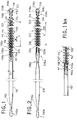
- the device of Figure 1 comprises an elongated cylindrical element 110 and a brush 112, provided at a first end 110a of the element 110, mounted on a longitudinal rod 114 and provided with bristles 116 substantially radial.
- the elongated cylindrical element was truncated, whose length can range from one to several meters, while its diameter is generally between 1 and 20 mm.
- this elongated cylindrical element consists of a smooth smooth fiber made plastic (such as Nylon, PVC or Teflon), for example by extrusion. It can also be made of reinforced plastic fiber. Of in general, the external surface of the element 110 is smooth. This element can therefore be simply coated with plastic.
- a protective cap 118 for example made of plastic, which has a rounded free end 118b, of diameter D2 substantially equal to the current diameter D1 of the fiber 110.
- current fiber diameter is meant the diameter of this last over most of its length, excluding any tightened parts. In fact, its current diameter also corresponds to its maximum diameter.
- the device comprises a member for holding the brush. Indeed, to increase efficiency, it is advantageous to provide the brush with a length relatively large.
- the holding member makes it possible to equip the device with brushes long, whose length is much greater than the diameter, for example between five and fifteen times the diameter, or even more.
- the holding member 120 of Figure 1 is mounted at the first end 110a of the fiber 110 and has an external diameter d1 substantially equal to the current diameter D1 of this fiber. It maintains the brush 112 over the entire length L 'of the latter. Indeed, the organ 120 protrudes beyond the end 110a of the fiber over a greater length to that of the brush. Similarly, the holding member 220 of FIG. 2, maintains the brush 212 over its entire length L ".
- the holding member 120 or 220 is constituted by a wire wound in propeller, whose turns 122 or 222 delimit a channel 124 or 224, suitable for receive the brush rod. On at least a section of this organ of holding, section whose length is at least equal to that of the brush, the turns are axially spaced from each other so as to allow the passage of the bristles of the brush.
- the bristles of the brush are preferably arranged in a helix and, on each turn of this propeller, grouped in groups of three or four hair or more.
- the spacing "e" between the turns of the holding member allows the passage of an entire turn of the bristles of the brush, and is therefore about three to twenty times the thickness of a hair.
- the pitch of the propeller of this organ is substantially equal to the pitch of the helix formed by the bristles of the brush.
- the end 110a of the fiber 110 is provided with a connection sleeve 126 capable of cooperating with the first end 120a of the retaining member 120 for connecting the latter to the fiber 110.
- This sleeve is substantially cylindrical and its current radius is smaller than the current radius of the fiber.
- the gap between these rays is substantially equal to the thickness of the wire which constitutes the holding member.
- the thread that constitutes the holding member may be metallic and it is preferable that it does not exceed not beyond the diametrical dimensions of the fiber to avoid scratching the duct that we clean.
- the hairs of the latter avoid any direct contact between the holding and the duct to be cleaned.
- the rod 114 of the brush is fixed to the first end 110a of the fiber.
- the end of this rod can indeed be engaged in a short axial bore of the fiber and be stuck in the latter. It then obviously passes through an axial bore of the sleeve 126.
- the brush is therefore constantly attached to fiber 110.
- the retaining member 120 of the Figure 1 is removable and can be mounted or removed at the first end of the fiber 110 by a screwing movement relative to the brush. In the mounting direction, the screwing movement continues until the end 120a of the holding member cooperates with the sleeve 126.
- the holding member 120 is fixed axially by screwing on the brush 112.
- the sleeve is constituted by an element attached and fixed to the end 110a of the fiber.
- the sleeve can indeed be consisting of a rigid piece, for example of metal, which while maintaining rigidly the end turns of the holding member makes it possible to initiate the curvature of the latter when the device is inserted into curves of the ducts to be cleaned. It is indeed important to prevent the holding member from is slightly offset radially from the fiber to avoid that it does not come into contact with the internal walls of the duct to be cleaned.
- the first end 110a of the fiber 110 has a cavity cylindrical 111.
- the sleeve 126 has a first part 126a housed in this cavity 111 and fixed to its walls.
- the sleeve has a second part 126b which protrudes beyond the first end 110a of the fiber. It is this second part which cooperates with the end 120a of the holding member.
- the external diameter of the second part 126b is less than or equal to the internal diameter of the holding member 120.
- This second part is used to guide the holding member during its screwing and especially, when this organ is in place, to prevent it from moving transversely to the axis of the rod 114.
- the sleeve has an axial hole of suitable size to that of the brush rod.
- the tip 118 has a first portion 118a of suitable diameter to that of the channel delimited by the turns of the holding member 120 and a second part 118b which has a rounded end. These two parts are connected to each other by a shoulder 118c capable of cooperate with the free end 120b of the holding member.
- the tip can be permanently fixed, by example by gluing, to the holding member 120, or be screwed into it last and, in this case, present a suitable thread.
- the second part 118b of the nozzle makes it possible to avoid any contact between this organ and the duct to be cleaned.
- Figure 1bis shows a mounting variant, using a sleeve cylindrical hollow 126 '.
- the end 110'a of the fiber 110 ' has a shoulder and an extreme portion of reduced diameter 111 '.
- the sleeve 126 ' is fitted onto this portion 111' and is fixed thereto. His external diameter is at most equal to that of the fiber 110 ′.
- the cylindrical cavity 127 'formed between the end of the fiber and the free end of the sleeve 126 ' serves as a housing for the first end 120'a of the holding member 120 '.
- This conformation avoids the travel of this first end 120'a relative to to the axis of the rod 114 'of the brush 112' on which the holding member is screwed.
- the first end 220a of the holding member is fixed to the sleeve 226.
- the brush 212 is then capable of being placed in said holding member by a screwing movement and to be released therefrom by a movement of unscrewing. It is held axially in the holding member thanks to the fact that its hairs pass between the turns of this latest.
- the sleeve 226 is substantially cylindrical and has a current radius smaller than the current radius of the fiber 210, the difference between these radii being substantially equal to the thickness of the wire which constitutes the holding member.
- the sleeve 226 is simply constituted by an extreme portion of reduced diameter of the end 210a of the fiber.
- the end 220a of the holding member is fixed to this sleeve 226 by any suitable means, such as gluing or screwing by force.
- the sleeve 226 may have a thread.
- the protective tip 218 has a first portion 218a, can be fixed to the rod 214 of the brush, of diameter adapted to that of the channel delimited by the turns of the holding member and connected to the rounded end 218b by a shoulder 218c capable of cooperating with the free end of the holding member.
- Brush 212 is therefore correctly positioned when the shoulder 218c abuts with the first turn of the free end 220b of the holding member.
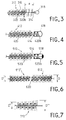
- Figures 3 to 5 show variants for which the tips can be metallic. To lighten these figures, only the regions end brushes are shown. The holding organs, likewise that the brushes, are of configurations similar to those previously described.
- the tip 318 is directly attached to the free end the rod 314 of the brush 312, by any suitable means such as crimping, bonding or screwing.
- the brush therefore protrudes a slight distance "a" beyond the free end 320b of the holding member 320. It is necessary however note that this free end is not aggressive since it is embedded in the bristles 316 of the brush.
- the distance "a" is low enough that the lack of support at the end of the brush does not affect its effectiveness or the strength of the rod.
- the diameter of the end piece 318 can be lower than that of the holding member.
- the end piece 418 covers the free end 420b of the member holding 420 and can be shrunk on the latter to be there definitely fixed.
- the rod 414 of the brush advantageously extends to the inside of the nozzle.
- the end piece 518 also covers the free end 520b of the holding member 520. However, this endpiece is directly fixed to the end of the rod 514 of the brush 512 by gluing, welding or any other analogous means.
- the assembly constituted by the brush 512 and the nozzle 518 can thus be removably mounted relative to the holding member 520.
- End caps 318, 418 and 518 are rounded to prevent damage ducts cleaned using the device.
- Figure 6 shows two brushes 612 and 612 'successively arranged in the holding member 620. These two brushes can therefore be arranged one after the other at the first end of the fiber. They have different diameters D and D '. They can be separated as shown in the figure, or joined by the same rod.
- FIG. 7 shows a brush 712 whose diameter varies over its length and increases between a small diameter D "and a large diameter D" '. This increase can be progressive as in the figure, in which case the brush is tapered. It can also be done gradually or in spurts, the brush may even have cylindrical portions and frustoconical portions. This conformation ensures that there is always a region of the brush in which the diameter of the bristles allows very effective cleaning of the duct.
- the brush 712 can be provided alone or associated with one or more other brushes such as cylindrical brushes 612 and 612 '.
- the fiber 110 of FIG. 1 has, in the vicinity of its second end 110b, a thinned section 110c whose flexibility is greater than that of its current part.
- this section is gradually thinned, which makes it possible to gradually vary the flexibility of the fiber in this region.
- This is also the case for fiber 210.
- the thinned section large flexibility, will be able to pass the elbows without difficulty and will therefore allow fully insert the device.
- the fiber 210 has another portion thinned 210d located near its first end 210a. This 210d portion provides significant local flexibility just before brushing 212.
- This second brush which can be fitted of a holding member similar to that which equips the first, is advantageously shorter and wider than the first. In this case, it is first the second brush which is inserted into the duct to be cleaned.
Landscapes
- Brushes (AREA)
- Cleaning In General (AREA)
- Surgical Instruments (AREA)
Applications Claiming Priority (2)
| Application Number | Priority Date | Filing Date | Title |
|---|---|---|---|
| FR9414363 | 1994-11-30 | ||
| FR9414363A FR2727334A1 (fr) | 1994-11-30 | 1994-11-30 | Dispositif de nettoyage de conduits d'instruments medicaux |
Publications (2)
| Publication Number | Publication Date |
|---|---|
| EP0714621A1 EP0714621A1 (fr) | 1996-06-05 |
| EP0714621B1 true EP0714621B1 (fr) | 1999-09-01 |
Family
ID=9469316
Family Applications (1)
| Application Number | Title | Priority Date | Filing Date |
|---|---|---|---|
| EP95402675A Expired - Lifetime EP0714621B1 (fr) | 1994-11-30 | 1995-11-28 | Dispositif de nettoyage de conduits d'instruments médicaux |
Country Status (5)
| Country | Link |
|---|---|
| US (1) | US5615439A (enExample) |
| EP (1) | EP0714621B1 (enExample) |
| AT (1) | ATE183898T1 (enExample) |
| DE (1) | DE69511825T2 (enExample) |
| FR (1) | FR2727334A1 (enExample) |
Families Citing this family (36)
| Publication number | Priority date | Publication date | Assignee | Title |
|---|---|---|---|---|
| US5964004A (en) * | 1996-09-24 | 1999-10-12 | Bean; Douglas Colin | Device for cleaning medical endoscopic tubes |
| USD394353S (en) | 1997-08-11 | 1998-05-19 | The Libman Company | Toilet bowl brush handle |
| US6725492B2 (en) * | 1998-11-25 | 2004-04-27 | Neosci Medical, Inc. | Cleaning brush for medical devices |
| FR2786675B1 (fr) | 1998-12-02 | 2001-02-23 | Technologie Avancee Medicale | Systeme de nettoyage de conduits d'instruments medicaux |
| US6295994B1 (en) * | 1999-12-21 | 2001-10-02 | Color Access, Inc. | Brush applicator with added helix |
| DE20010384U1 (de) | 2000-06-09 | 2001-10-11 | Fitjer, Holger H., 81669 München | Applikator, insbesondere Mascara-Bürstchen |
| US6354337B1 (en) * | 2000-08-28 | 2002-03-12 | The Pampered Chef, Ltd. | Oven baster and cleaning brush |
| US6484345B2 (en) * | 2001-02-13 | 2002-11-26 | Helix Medical, Inc. | Voice prosthesis brush |
| US20030213501A1 (en) * | 2002-04-06 | 2003-11-20 | Timothy Thomson | Apparatus and method for cleaning an endoscope |
| FR2842751B1 (fr) * | 2002-07-29 | 2004-10-15 | Odon Life Technology | Ecouvillon pour canal operateur d'endoscope et procede de fabrication de tels ecouvillons |
| US20040187892A1 (en) * | 2003-03-31 | 2004-09-30 | Maguire Walter L. | Scrubbing element with leader |
| US20040187893A1 (en) * | 2003-03-31 | 2004-09-30 | Maguire Walter L. | Scrubbing element with enzyme/hydrophilic |
| US7025068B2 (en) * | 2003-06-24 | 2006-04-11 | Geka Brush Gmbh | Applicator, in particular mascara brush |
| GB0402249D0 (en) * | 2004-02-02 | 2004-03-03 | Idi Technologies Ltd | Brush |
| US20060102200A1 (en) * | 2004-11-18 | 2006-05-18 | Bernard Esquenet | Cannula cleaning device |
| USD658388S1 (en) * | 2005-01-25 | 2012-05-01 | Atos Medical Ab | Brush |
| ES2265286B1 (es) * | 2005-07-18 | 2007-12-01 | Dols Industrial De Peluqueria, S.A. | "cepillo para el cabello". |
| JP2009119176A (ja) * | 2007-11-19 | 2009-06-04 | Junko Nakano | 液塗布具 |
| US8262645B2 (en) * | 2007-11-21 | 2012-09-11 | Actuated Medical, Inc. | Devices for clearing blockages in in-situ artificial lumens |
| EP3329955B1 (en) | 2009-02-06 | 2020-10-21 | Endoclear LLC | Device for cleaning endotracheal tubes |
| US8468637B2 (en) | 2009-02-06 | 2013-06-25 | Endoclear Llc | Mechanically-actuated endotracheal tube cleaning device |
| US9445714B2 (en) | 2010-03-29 | 2016-09-20 | Endoclear Llc | Endotracheal tube coupling adapters |
| EP2552293B1 (en) | 2010-03-29 | 2015-01-07 | Endoclear LLC | Airway cleaning and visualization |
| WO2012054480A2 (en) * | 2010-10-19 | 2012-04-26 | United States Endoscopy Group, Inc. | Cytology brush apparatus with improvements |
| US8668642B2 (en) | 2010-11-23 | 2014-03-11 | Covidien Lp | Port device including retractable endoscope cleaner |
| US9486129B2 (en) * | 2012-02-29 | 2016-11-08 | Risen Star Industries, Llc | Method and apparatus for cleaning an endoscope |
| US9615893B2 (en) | 2012-11-14 | 2017-04-11 | Covidien Lp | Seal cleaning obturator |
| EP2928517B2 (en) | 2012-12-04 | 2025-08-27 | SunMed Group Holdings, LLC | Suction cleaning devices |
| ES2647517T3 (es) * | 2014-03-10 | 2017-12-22 | Mybrush Gmbh | Cepillo para la limpieza interior de un catéter flexible |
| WO2015168693A1 (en) | 2014-05-02 | 2015-11-05 | United States Endoscopy Group, Inc. | Cleaning device for an endoscopic device |
| US10016575B2 (en) | 2014-06-03 | 2018-07-10 | Endoclear Llc | Cleaning devices, systems and methods |
| USD854837S1 (en) * | 2017-09-18 | 2019-07-30 | Lta Medical | Brush for cleaning medical devices |
| USD849346S1 (en) | 2017-11-14 | 2019-05-21 | Darline Lewis | CPAP mask-cleaning sponge |
| CN110038861B (zh) * | 2019-04-12 | 2021-06-22 | 吉林大学 | 一种消融导管用后清洁消毒装置 |
| US20210236235A1 (en) * | 2019-08-12 | 2021-08-05 | Dennis Werger | Apparatus for drying and sanitizing reusable tubular medical devices |
| CN112826427A (zh) * | 2021-02-25 | 2021-05-25 | 上海汤武医疗器械有限公司 | 一种软式内镜动力工具清洗刷 |
Family Cites Families (9)
| Publication number | Priority date | Publication date | Assignee | Title |
|---|---|---|---|---|
| CA491788A (en) * | 1953-04-07 | Boyko Emil | Flexible brush | |
| US1825929A (en) * | 1930-04-14 | 1931-10-06 | Gust H Voigt | Brush |
| US2421647A (en) * | 1943-04-22 | 1947-06-03 | Osborn Mfg Co | End brush |
| US2824322A (en) * | 1955-11-21 | 1958-02-25 | Nicholas J Angelica | Chamber cleaning tool |
| US3613664A (en) * | 1969-06-25 | 1971-10-19 | Marshall Eskridge | Controllable tip brush for medical use |
| US4167192A (en) * | 1977-08-15 | 1979-09-11 | Trisa Burstenfabrik Ag Triengen | Circular brush |
| US4512810A (en) * | 1984-01-18 | 1985-04-23 | International Harvester Company | Bolster pin and method for cleaning flask bushing |
| DE4022890A1 (de) * | 1990-07-18 | 1992-01-23 | Geka Brush Georg Karl Gmbh | Buerste, insbesondere mascara-buerste |
| US5168593A (en) * | 1991-11-01 | 1992-12-08 | Mill-Rose Laboratories, Inc. | Tool for cleaning endoscopes |
-
1994
- 1994-11-30 FR FR9414363A patent/FR2727334A1/fr active Granted
-
1995
- 1995-11-27 US US08/562,980 patent/US5615439A/en not_active Expired - Lifetime
- 1995-11-28 AT AT95402675T patent/ATE183898T1/de not_active IP Right Cessation
- 1995-11-28 DE DE69511825T patent/DE69511825T2/de not_active Expired - Lifetime
- 1995-11-28 EP EP95402675A patent/EP0714621B1/fr not_active Expired - Lifetime
Also Published As
| Publication number | Publication date |
|---|---|
| FR2727334A1 (fr) | 1996-05-31 |
| EP0714621A1 (fr) | 1996-06-05 |
| ATE183898T1 (de) | 1999-09-15 |
| DE69511825D1 (de) | 1999-10-07 |
| FR2727334B1 (enExample) | 1997-02-14 |
| US5615439A (en) | 1997-04-01 |
| DE69511825T2 (de) | 2000-03-09 |
Similar Documents
| Publication | Publication Date | Title |
|---|---|---|
| EP0714621B1 (fr) | Dispositif de nettoyage de conduits d'instruments médicaux | |
| EP0575478B1 (fr) | Filtre anti-embolie pulmonaire perfectionne et kit de presentation et mise en place correspondante | |
| CA2648069C (fr) | Protection pour endoscope et endoscope correspondant | |
| CH690088A5 (fr) | Guide tubulaire flexible orientable, notamment pour un dispositif médico-chirurgical. | |
| US5578056A (en) | Separable economically partially disposable flexible biopsy forceps | |
| FR2738736A1 (fr) | Instrument endoscopique a tige flexible | |
| EP0900033B1 (fr) | Brosse a dents dite transversale | |
| EP0214063A1 (fr) | Sonde intracorporelle et dispositif de montage des ballonnets d'une telle sonde | |
| CA2825523A1 (fr) | Dispositif de forage pour la realisation d'un canal osseux a profil courbe a l'interieur du corps d'une vertebre | |
| FR2710259A1 (fr) | Appareil applicateur de verre de contact. | |
| EP0441676A1 (fr) | Connecteur pour fibres optiques | |
| FR2513392A1 (fr) | Cellule de centrage pour raccordement de fibres optiques | |
| FR3047887A1 (fr) | Dispositif medical avec une partie de bequillage a ressort helicoidal | |
| FR2477006A1 (fr) | Appareil de transfert d'elements de reproduction animale, notamment d'embryons | |
| EP2043532B1 (fr) | Systeme intra-uterin recuperable | |
| CA2520294C (fr) | Dispositif de nettoyage des espaces inter-dentaires | |
| FR2946865A1 (fr) | Dispositif de traitement d'un conduit de circulation du sang | |
| EP2120818A1 (fr) | Pointe de micromanipulateur chirurgical, micromanipulateur chirurgical et procede de fabrication d'une pointe pour un tel micromanipulateur | |
| WO2009156665A2 (fr) | Composant de brosse a mascara, brosse a mascara et ensemble d'application de mascara | |
| FR2639237A1 (fr) | Catheter destine a etre introduit dans un canal corporel | |
| FR2786675A1 (fr) | Systeme de nettoyage de conduits d'instruments medicaux | |
| FR2814670A1 (fr) | Dispositif de filtration temporaire a raidisseur effile | |
| JPH03184011A (ja) | 工業用内視鏡の挿入部保護チューブ | |
| FR2917283A1 (fr) | Instrument de pose d'une prothese d'epaule. | |
| FR2894457A1 (fr) | Instrument endoscopique |
Legal Events
| Date | Code | Title | Description |
|---|---|---|---|
| PUAI | Public reference made under article 153(3) epc to a published international application that has entered the european phase |
Free format text: ORIGINAL CODE: 0009012 |
|
| AK | Designated contracting states |
Kind code of ref document: A1 Designated state(s): AT BE CH DE ES FR IT LI NL |
|
| 17P | Request for examination filed |
Effective date: 19961025 |
|
| GRAG | Despatch of communication of intention to grant |
Free format text: ORIGINAL CODE: EPIDOS AGRA |
|
| 17Q | First examination report despatched |
Effective date: 19980730 |
|
| GRAG | Despatch of communication of intention to grant |
Free format text: ORIGINAL CODE: EPIDOS AGRA |
|
| GRAH | Despatch of communication of intention to grant a patent |
Free format text: ORIGINAL CODE: EPIDOS IGRA |
|
| GRAH | Despatch of communication of intention to grant a patent |
Free format text: ORIGINAL CODE: EPIDOS IGRA |
|
| GRAA | (expected) grant |
Free format text: ORIGINAL CODE: 0009210 |
|
| AK | Designated contracting states |
Kind code of ref document: B1 Designated state(s): AT BE CH DE ES FR IT LI NL |
|
| PG25 | Lapsed in a contracting state [announced via postgrant information from national office to epo] |
Ref country code: NL Free format text: LAPSE BECAUSE OF FAILURE TO SUBMIT A TRANSLATION OF THE DESCRIPTION OR TO PAY THE FEE WITHIN THE PRESCRIBED TIME-LIMIT Effective date: 19990901 Ref country code: ES Free format text: THE PATENT HAS BEEN ANNULLED BY A DECISION OF A NATIONAL AUTHORITY Effective date: 19990901 |
|
| REF | Corresponds to: |
Ref document number: 183898 Country of ref document: AT Date of ref document: 19990915 Kind code of ref document: T |
|
| REG | Reference to a national code |
Ref country code: CH Ref legal event code: EP |
|
| REF | Corresponds to: |
Ref document number: 69511825 Country of ref document: DE Date of ref document: 19991007 |
|
| ITF | It: translation for a ep patent filed | ||
| REG | Reference to a national code |
Ref country code: CH Ref legal event code: NV Representative=s name: DIETLIN & CIE S.A. |
|
| NLV1 | Nl: lapsed or annulled due to failure to fulfill the requirements of art. 29p and 29m of the patents act | ||
| PLBE | No opposition filed within time limit |
Free format text: ORIGINAL CODE: 0009261 |
|
| STAA | Information on the status of an ep patent application or granted ep patent |
Free format text: STATUS: NO OPPOSITION FILED WITHIN TIME LIMIT |
|
| 26N | No opposition filed | ||
| PGFP | Annual fee paid to national office [announced via postgrant information from national office to epo] |
Ref country code: AT Payment date: 20021018 Year of fee payment: 8 |
|
| PGFP | Annual fee paid to national office [announced via postgrant information from national office to epo] |
Ref country code: CH Payment date: 20021118 Year of fee payment: 8 |
|
| PGFP | Annual fee paid to national office [announced via postgrant information from national office to epo] |
Ref country code: BE Payment date: 20021212 Year of fee payment: 8 |
|
| PG25 | Lapsed in a contracting state [announced via postgrant information from national office to epo] |
Ref country code: AT Free format text: LAPSE BECAUSE OF NON-PAYMENT OF DUE FEES Effective date: 20031128 |
|
| PG25 | Lapsed in a contracting state [announced via postgrant information from national office to epo] |
Ref country code: LI Free format text: LAPSE BECAUSE OF NON-PAYMENT OF DUE FEES Effective date: 20031130 Ref country code: CH Free format text: LAPSE BECAUSE OF NON-PAYMENT OF DUE FEES Effective date: 20031130 Ref country code: BE Free format text: LAPSE BECAUSE OF NON-PAYMENT OF DUE FEES Effective date: 20031130 |
|
| BERE | Be: lapsed |
Owner name: *LA TECHNOLOGIE AVANCEE MEDICALE Effective date: 20031130 |
|
| REG | Reference to a national code |
Ref country code: CH Ref legal event code: PL |
|
| PGFP | Annual fee paid to national office [announced via postgrant information from national office to epo] |
Ref country code: IT Payment date: 20061130 Year of fee payment: 12 |
|
| PG25 | Lapsed in a contracting state [announced via postgrant information from national office to epo] |
Ref country code: IT Free format text: LAPSE BECAUSE OF NON-PAYMENT OF DUE FEES Effective date: 20071128 |
|
| PGFP | Annual fee paid to national office [announced via postgrant information from national office to epo] |
Ref country code: DE Payment date: 20141113 Year of fee payment: 20 |
|
| PGFP | Annual fee paid to national office [announced via postgrant information from national office to epo] |
Ref country code: FR Payment date: 20141126 Year of fee payment: 20 |
|
| REG | Reference to a national code |
Ref country code: DE Ref legal event code: R071 Ref document number: 69511825 Country of ref document: DE |