EP0714621B1 - Cleaning device for ducts of medical instruments - Google Patents
Cleaning device for ducts of medical instruments Download PDFInfo
- Publication number
- EP0714621B1 EP0714621B1 EP95402675A EP95402675A EP0714621B1 EP 0714621 B1 EP0714621 B1 EP 0714621B1 EP 95402675 A EP95402675 A EP 95402675A EP 95402675 A EP95402675 A EP 95402675A EP 0714621 B1 EP0714621 B1 EP 0714621B1
- Authority
- EP
- European Patent Office
- Prior art keywords
- brush
- rod
- support member
- diameter
- sleeve
- Prior art date
- Legal status (The legal status is an assumption and is not a legal conclusion. Google has not performed a legal analysis and makes no representation as to the accuracy of the status listed.)
- Expired - Lifetime
Links
- 238000004140 cleaning Methods 0.000 title claims description 11
- 238000011838 internal investigation Methods 0.000 claims abstract description 3
- 230000008878 coupling Effects 0.000 claims 3
- 238000010168 coupling process Methods 0.000 claims 3
- 238000005859 coupling reaction Methods 0.000 claims 3
- 238000005070 sampling Methods 0.000 abstract description 5
- 238000004804 winding Methods 0.000 abstract 1
- 239000000835 fiber Substances 0.000 description 37
- 210000000056 organ Anatomy 0.000 description 7
- 210000004209 hair Anatomy 0.000 description 5
- 238000004026 adhesive bonding Methods 0.000 description 3
- 239000004033 plastic Substances 0.000 description 3
- 229920003023 plastic Polymers 0.000 description 3
- 238000011835 investigation Methods 0.000 description 2
- 230000001681 protective effect Effects 0.000 description 2
- 239000004677 Nylon Substances 0.000 description 1
- 239000004809 Teflon Substances 0.000 description 1
- 229920006362 Teflon® Polymers 0.000 description 1
- 238000005452 bending Methods 0.000 description 1
- 230000001680 brushing effect Effects 0.000 description 1
- 238000002788 crimping Methods 0.000 description 1
- 230000001627 detrimental effect Effects 0.000 description 1
- 238000001839 endoscopy Methods 0.000 description 1
- 238000001125 extrusion Methods 0.000 description 1
- 238000012423 maintenance Methods 0.000 description 1
- 239000002184 metal Substances 0.000 description 1
- 229920001778 nylon Polymers 0.000 description 1
- 230000003287 optical effect Effects 0.000 description 1
- 239000004800 polyvinyl chloride Substances 0.000 description 1
- 229920000915 polyvinyl chloride Polymers 0.000 description 1
- 230000000750 progressive effect Effects 0.000 description 1
- 239000002990 reinforced plastic Substances 0.000 description 1
- 238000006748 scratching Methods 0.000 description 1
- 230000002393 scratching effect Effects 0.000 description 1
- 239000007787 solid Substances 0.000 description 1
- 238000003466 welding Methods 0.000 description 1
Images
Classifications
-
- A—HUMAN NECESSITIES
- A46—BRUSHWARE
- A46B—BRUSHES
- A46B3/00—Brushes characterised by the way in which the bristles are fixed or joined in or on the brush body or carrier
- A46B3/18—Brushes characterised by the way in which the bristles are fixed or joined in or on the brush body or carrier the bristles being fixed on or between belts or wires
-
- A—HUMAN NECESSITIES
- A61—MEDICAL OR VETERINARY SCIENCE; HYGIENE
- A61B—DIAGNOSIS; SURGERY; IDENTIFICATION
- A61B90/00—Instruments, implements or accessories specially adapted for surgery or diagnosis and not covered by any of the groups A61B1/00 - A61B50/00, e.g. for luxation treatment or for protecting wound edges
- A61B90/70—Cleaning devices specially adapted for surgical instruments
- A61B2090/701—Cleaning devices specially adapted for surgical instruments for flexible tubular instruments, e.g. endoscopes
-
- A—HUMAN NECESSITIES
- A61—MEDICAL OR VETERINARY SCIENCE; HYGIENE
- A61B—DIAGNOSIS; SURGERY; IDENTIFICATION
- A61B90/00—Instruments, implements or accessories specially adapted for surgery or diagnosis and not covered by any of the groups A61B1/00 - A61B50/00, e.g. for luxation treatment or for protecting wound edges
- A61B90/70—Cleaning devices specially adapted for surgical instruments
-
- A—HUMAN NECESSITIES
- A61—MEDICAL OR VETERINARY SCIENCE; HYGIENE
- A61M—DEVICES FOR INTRODUCING MEDIA INTO, OR ONTO, THE BODY; DEVICES FOR TRANSDUCING BODY MEDIA OR FOR TAKING MEDIA FROM THE BODY; DEVICES FOR PRODUCING OR ENDING SLEEP OR STUPOR
- A61M25/00—Catheters; Hollow probes
- A61M2025/0019—Cleaning catheters or the like, e.g. for reuse of the device, for avoiding replacement
Definitions
- the present invention relates to a device for cleaning ducts medical instruments for internal investigation or sampling, comprising an elongate cylindrical member having a smooth outer surface and a brush, provided at a first end of said element, mounted on a longitudinal rod and having substantially radial bristles.
- instruments of investigation or internal sampling we mean instruments like those usually used to endoscopy examinations, presenting a conduit that is introduced into the patient's body and into which medical tools such as optical devices, sampling tools or tools surgical.
- This device must have sufficient radial dimensions weak to be able to fit into the conduit, the diameter of which is generally small, for example of the order of 1 to 20 mm. Furthermore, the device must be flexible enough to fit any bends in the duct and, in particular, to be able to perfectly clean the bifurcation zones. Despite its small radial dimensions and its flexibility, the device must have relative axial rigidity, i.e. sufficient resistance to pulling and pushing, so that it can be inserted, being pushed by a from its ends, along the entire length of the conduit which can reach one or two meters.
- US Patent 5,168,593 shows a cleaning device in which the brush is connected to the cylindrical support element via of a coil spring. More specifically, the rod of the brush is fixed to a first end of the spring, the other end of the latter being fixed to the elongated cylindrical member.
- the brush rod serving to support the bristles it is not possible to give it only radial flexibility, without making it equally axially flexible.
- a first solution is to provide it with a flexible rod.
- axial flexibility is detrimental to the introduction of the brush in the ducts and directly questions its effectiveness. Any so simply putting a long brush with a flexible rod is not satisfactory insofar as such a rod is not in itself enough solid and breaks after repeated bending.
- a second solution consists in making a very short brush (of length substantially equal to its diameter), with a rigid rod, in based on the fact that given the short length of the brush, it is not no need for the rod to bend strongly, even in areas with strong curvature.
- Such a brush has the disadvantage of being too short to properly clean some particularly dirty conduits.
- the invention aims to remedy the aforementioned drawbacks.
- the device further comprises a holding member of the brush, mounted at the first end of the fiber, of external diameter substantially equal to that of this fiber and capable of holding the brush over substantially the entire length of the latter, said member being consisting of a helically wound wire, the turns of which define a suitable channel to receive the rod of the brush, and having a section, of length substantially equal to that of the brush, on which the turns are spaced axially so as to allow the passage of the bristles of the brush between these turns.
- a holding member of the brush mounted at the first end of the fiber, of external diameter substantially equal to that of this fiber and capable of holding the brush over substantially the entire length of the latter, said member being consisting of a helically wound wire, the turns of which define a suitable channel to receive the rod of the brush, and having a section, of length substantially equal to that of the brush, on which the turns are spaced axially so as to allow the passage of the bristles of the brush between these turns.
- the invention makes it possible to use a brush long, mounted on a flexible rod, without this flexibility affecting the effectiveness of cleaning or inserting the brush into the conduit clean, this brush being held axially by the holding member, without this opposing the radial flexibility necessary for the passage in areas with strong curvatures.
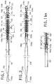
- the device of Figure 1 comprises an elongated cylindrical element 110 and a brush 112, provided at a first end 110a of the element 110, mounted on a longitudinal rod 114 and provided with bristles 116 substantially radial.
- the elongated cylindrical element was truncated, whose length can range from one to several meters, while its diameter is generally between 1 and 20 mm.
- this elongated cylindrical element consists of a smooth smooth fiber made plastic (such as Nylon, PVC or Teflon), for example by extrusion. It can also be made of reinforced plastic fiber. Of in general, the external surface of the element 110 is smooth. This element can therefore be simply coated with plastic.
- a protective cap 118 for example made of plastic, which has a rounded free end 118b, of diameter D2 substantially equal to the current diameter D1 of the fiber 110.
- current fiber diameter is meant the diameter of this last over most of its length, excluding any tightened parts. In fact, its current diameter also corresponds to its maximum diameter.
- the device comprises a member for holding the brush. Indeed, to increase efficiency, it is advantageous to provide the brush with a length relatively large.
- the holding member makes it possible to equip the device with brushes long, whose length is much greater than the diameter, for example between five and fifteen times the diameter, or even more.
- the holding member 120 of Figure 1 is mounted at the first end 110a of the fiber 110 and has an external diameter d1 substantially equal to the current diameter D1 of this fiber. It maintains the brush 112 over the entire length L 'of the latter. Indeed, the organ 120 protrudes beyond the end 110a of the fiber over a greater length to that of the brush. Similarly, the holding member 220 of FIG. 2, maintains the brush 212 over its entire length L ".
- the holding member 120 or 220 is constituted by a wire wound in propeller, whose turns 122 or 222 delimit a channel 124 or 224, suitable for receive the brush rod. On at least a section of this organ of holding, section whose length is at least equal to that of the brush, the turns are axially spaced from each other so as to allow the passage of the bristles of the brush.
- the bristles of the brush are preferably arranged in a helix and, on each turn of this propeller, grouped in groups of three or four hair or more.
- the spacing "e" between the turns of the holding member allows the passage of an entire turn of the bristles of the brush, and is therefore about three to twenty times the thickness of a hair.
- the pitch of the propeller of this organ is substantially equal to the pitch of the helix formed by the bristles of the brush.
- the end 110a of the fiber 110 is provided with a connection sleeve 126 capable of cooperating with the first end 120a of the retaining member 120 for connecting the latter to the fiber 110.
- This sleeve is substantially cylindrical and its current radius is smaller than the current radius of the fiber.
- the gap between these rays is substantially equal to the thickness of the wire which constitutes the holding member.
- the thread that constitutes the holding member may be metallic and it is preferable that it does not exceed not beyond the diametrical dimensions of the fiber to avoid scratching the duct that we clean.
- the hairs of the latter avoid any direct contact between the holding and the duct to be cleaned.
- the rod 114 of the brush is fixed to the first end 110a of the fiber.
- the end of this rod can indeed be engaged in a short axial bore of the fiber and be stuck in the latter. It then obviously passes through an axial bore of the sleeve 126.
- the brush is therefore constantly attached to fiber 110.
- the retaining member 120 of the Figure 1 is removable and can be mounted or removed at the first end of the fiber 110 by a screwing movement relative to the brush. In the mounting direction, the screwing movement continues until the end 120a of the holding member cooperates with the sleeve 126.
- the holding member 120 is fixed axially by screwing on the brush 112.
- the sleeve is constituted by an element attached and fixed to the end 110a of the fiber.
- the sleeve can indeed be consisting of a rigid piece, for example of metal, which while maintaining rigidly the end turns of the holding member makes it possible to initiate the curvature of the latter when the device is inserted into curves of the ducts to be cleaned. It is indeed important to prevent the holding member from is slightly offset radially from the fiber to avoid that it does not come into contact with the internal walls of the duct to be cleaned.
- the first end 110a of the fiber 110 has a cavity cylindrical 111.
- the sleeve 126 has a first part 126a housed in this cavity 111 and fixed to its walls.
- the sleeve has a second part 126b which protrudes beyond the first end 110a of the fiber. It is this second part which cooperates with the end 120a of the holding member.
- the external diameter of the second part 126b is less than or equal to the internal diameter of the holding member 120.
- This second part is used to guide the holding member during its screwing and especially, when this organ is in place, to prevent it from moving transversely to the axis of the rod 114.
- the sleeve has an axial hole of suitable size to that of the brush rod.
- the tip 118 has a first portion 118a of suitable diameter to that of the channel delimited by the turns of the holding member 120 and a second part 118b which has a rounded end. These two parts are connected to each other by a shoulder 118c capable of cooperate with the free end 120b of the holding member.
- the tip can be permanently fixed, by example by gluing, to the holding member 120, or be screwed into it last and, in this case, present a suitable thread.
- the second part 118b of the nozzle makes it possible to avoid any contact between this organ and the duct to be cleaned.
- Figure 1bis shows a mounting variant, using a sleeve cylindrical hollow 126 '.
- the end 110'a of the fiber 110 ' has a shoulder and an extreme portion of reduced diameter 111 '.
- the sleeve 126 ' is fitted onto this portion 111' and is fixed thereto. His external diameter is at most equal to that of the fiber 110 ′.
- the cylindrical cavity 127 'formed between the end of the fiber and the free end of the sleeve 126 ' serves as a housing for the first end 120'a of the holding member 120 '.
- This conformation avoids the travel of this first end 120'a relative to to the axis of the rod 114 'of the brush 112' on which the holding member is screwed.
- the first end 220a of the holding member is fixed to the sleeve 226.
- the brush 212 is then capable of being placed in said holding member by a screwing movement and to be released therefrom by a movement of unscrewing. It is held axially in the holding member thanks to the fact that its hairs pass between the turns of this latest.
- the sleeve 226 is substantially cylindrical and has a current radius smaller than the current radius of the fiber 210, the difference between these radii being substantially equal to the thickness of the wire which constitutes the holding member.
- the sleeve 226 is simply constituted by an extreme portion of reduced diameter of the end 210a of the fiber.
- the end 220a of the holding member is fixed to this sleeve 226 by any suitable means, such as gluing or screwing by force.
- the sleeve 226 may have a thread.
- the protective tip 218 has a first portion 218a, can be fixed to the rod 214 of the brush, of diameter adapted to that of the channel delimited by the turns of the holding member and connected to the rounded end 218b by a shoulder 218c capable of cooperating with the free end of the holding member.
- Brush 212 is therefore correctly positioned when the shoulder 218c abuts with the first turn of the free end 220b of the holding member.
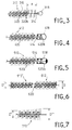
- Figures 3 to 5 show variants for which the tips can be metallic. To lighten these figures, only the regions end brushes are shown. The holding organs, likewise that the brushes, are of configurations similar to those previously described.
- the tip 318 is directly attached to the free end the rod 314 of the brush 312, by any suitable means such as crimping, bonding or screwing.
- the brush therefore protrudes a slight distance "a" beyond the free end 320b of the holding member 320. It is necessary however note that this free end is not aggressive since it is embedded in the bristles 316 of the brush.
- the distance "a" is low enough that the lack of support at the end of the brush does not affect its effectiveness or the strength of the rod.
- the diameter of the end piece 318 can be lower than that of the holding member.
- the end piece 418 covers the free end 420b of the member holding 420 and can be shrunk on the latter to be there definitely fixed.
- the rod 414 of the brush advantageously extends to the inside of the nozzle.
- the end piece 518 also covers the free end 520b of the holding member 520. However, this endpiece is directly fixed to the end of the rod 514 of the brush 512 by gluing, welding or any other analogous means.
- the assembly constituted by the brush 512 and the nozzle 518 can thus be removably mounted relative to the holding member 520.
- End caps 318, 418 and 518 are rounded to prevent damage ducts cleaned using the device.
- Figure 6 shows two brushes 612 and 612 'successively arranged in the holding member 620. These two brushes can therefore be arranged one after the other at the first end of the fiber. They have different diameters D and D '. They can be separated as shown in the figure, or joined by the same rod.
- FIG. 7 shows a brush 712 whose diameter varies over its length and increases between a small diameter D "and a large diameter D" '. This increase can be progressive as in the figure, in which case the brush is tapered. It can also be done gradually or in spurts, the brush may even have cylindrical portions and frustoconical portions. This conformation ensures that there is always a region of the brush in which the diameter of the bristles allows very effective cleaning of the duct.
- the brush 712 can be provided alone or associated with one or more other brushes such as cylindrical brushes 612 and 612 '.
- the fiber 110 of FIG. 1 has, in the vicinity of its second end 110b, a thinned section 110c whose flexibility is greater than that of its current part.
- this section is gradually thinned, which makes it possible to gradually vary the flexibility of the fiber in this region.
- This is also the case for fiber 210.
- the thinned section large flexibility, will be able to pass the elbows without difficulty and will therefore allow fully insert the device.
- the fiber 210 has another portion thinned 210d located near its first end 210a. This 210d portion provides significant local flexibility just before brushing 212.
- This second brush which can be fitted of a holding member similar to that which equips the first, is advantageously shorter and wider than the first. In this case, it is first the second brush which is inserted into the duct to be cleaned.
Abstract
Description
La présente invention concerne un dispositif de nettoyage de conduits d'instruments médicaux d'investigation ou de prélèvement interne, comprenant un élément cylindrique allongé ayant une surface externe lisse et une brosse, prévue à une première extrémité dudit élément, montée sur une tige longitudinale et présentant des poils sensiblement radiaux.The present invention relates to a device for cleaning ducts medical instruments for internal investigation or sampling, comprising an elongate cylindrical member having a smooth outer surface and a brush, provided at a first end of said element, mounted on a longitudinal rod and having substantially radial bristles.
Par instruments médicaux d'investigation ou de prélèvement interne, on entend des instruments comme ceux qui sont habituellement utilisés pour les examens d'endoscopie, présentant un conduit qu'on introduit dans le corps du patient et dans lequel on insère des outils médicaux tels que des appareils optiques, des outils de prélèvement ou encore des outils chirurgicaux.By medical instruments of investigation or internal sampling, we mean instruments like those usually used to endoscopy examinations, presenting a conduit that is introduced into the patient's body and into which medical tools such as optical devices, sampling tools or tools surgical.
De tels instruments sont relativement coûteux et doivent donc pouvoir être utilisés plusieurs fois. Entre deux utilisations, ils doivent subir un nettoyage rigoureux, puis être décontaminés ou stérilisés. Le nettoyage de l'intérieur des conduits s'avère très délicat et nécessite l'utilisation, à la manière d'un écouvillon, d'un dispositif du type précité.Such instruments are relatively expensive and therefore must be able to be used several times. Between two uses, they must undergo a rigorous cleaning, then be decontaminated or sterilized. Cleaning from the inside of the conduits is very delicate and requires the use, at the like a swab, a device of the aforementioned type.
Ce dispositif doit présenter des dimensions radiales suffisamment faibles pour pouvoir s'insérer dans le conduit, dont le diamètre est en général petit, par exemple de l'ordre de 1 à 20 mm. Par ailleurs, le dispositif doit être suffisamment flexible pour pouvoir épouser les coudes éventuels du conduit et, notamment, pour pouvoir parfaitement nettoyer les zones de bifurcation. Malgré ses faibles dimensions radiales et sa flexibilité, le dispositif doit présenter une relative rigidité axiale, c'est-à-dire une tenue suffisante à la traction et à la poussée, afin de pouvoir être inséré, en étant poussé par une de ses extrémités, dans toute la longueur du conduit qui peut atteindre un ou deux mètres.This device must have sufficient radial dimensions weak to be able to fit into the conduit, the diameter of which is generally small, for example of the order of 1 to 20 mm. Furthermore, the device must be flexible enough to fit any bends in the duct and, in particular, to be able to perfectly clean the bifurcation zones. Despite its small radial dimensions and its flexibility, the device must have relative axial rigidity, i.e. sufficient resistance to pulling and pushing, so that it can be inserted, being pushed by a from its ends, along the entire length of the conduit which can reach one or two meters.
Le brevet US 5 168 593 montre un dispositif de nettoyage dans lequel la brosse est raccordée à l'élément cylindrique de support par l'intermédiaire d'un ressort hélicoïdal. Plus précisément, la tige de la brosse est fixée à une première extrémité du ressort, l'autre extrémité de ce dernier étant fixée à l'élément cylindrique allongé.US Patent 5,168,593 shows a cleaning device in which the brush is connected to the cylindrical support element via of a coil spring. More specifically, the rod of the brush is fixed to a first end of the spring, the other end of the latter being fixed to the elongated cylindrical member.
Ceci permet de rendre flexible la liaison entre la brosse et l'élément cylindrique.This makes the connection between the brush and the element flexible. cylindrical.
Malheureusement, ces dispositions ne confèrent aucune flexibilité à la brosse en elle-même. Unfortunately, these provisions do not give flexibility to the brush itself.
La tige de la brosse servant de support aux poils, il n'est pas possible de lui conférer seulement une flexibilité radiale, sans la rendre également axialement flexible.The brush rod serving to support the bristles, it is not possible to give it only radial flexibility, without making it equally axially flexible.
Pour permettre à la brosse de passer dans des zones des conduits à forte courbure, une première solution consiste à la doter d'une tige flexible. Malheureusement, la flexibilité axiale est nuisible à l'introduction de la brosse dans les conduits et met directement en cause son efficacité. De toute façon, le simple fait de doter une brosse longue d'une tige flexible n'est pas satisfaisant dans la mesure où une telle tige n'est pas en elle-même assez solide et se casse après des flexions répétées.To allow the brush to pass through areas of the strong curvature, a first solution is to provide it with a flexible rod. Unfortunately, axial flexibility is detrimental to the introduction of the brush in the ducts and directly questions its effectiveness. Any so simply putting a long brush with a flexible rod is not satisfactory insofar as such a rod is not in itself enough solid and breaks after repeated bending.
Une deuxième solution consiste à réaliser une brosse très courte (de longueur sensiblement égale à son diamètre), dotée d'une tige rigide, en s'appuyant sur le fait qu'étant donné la faible longueur de la brosse, il n'est pas nécessaire que la tige se plie fortement, même dans des zones à fortes courbure. Une telle brosse présente l'inconvénient d'être trop courte pour correctement nettoyer certains conduits particulièrement sales.A second solution consists in making a very short brush (of length substantially equal to its diameter), with a rigid rod, in based on the fact that given the short length of the brush, it is not no need for the rod to bend strongly, even in areas with strong curvature. Such a brush has the disadvantage of being too short to properly clean some particularly dirty conduits.
Le fait de conférer au dispositif une souplesse locale dans la zone de liaison entre la brosse et l'élément cylindrique de support (lui-même suffisamment souple radialement et suffisamment rigide axialement) ne suffit donc pas à assurer la fiabilité du dispositif.Giving the device local flexibility in the area of connection between the brush and the cylindrical support element (itself sufficiently flexible radially and sufficiently rigid axially) does not therefore not sufficient to ensure the reliability of the device.
L'invention a pour but de remédier aux inconvénients précités.The invention aims to remedy the aforementioned drawbacks.
Dans ce but, le dispositif comporte, en outre, un organe de maintien de la brosse, monté à la première extrémité de la fibre, de diamètre externe sensiblement égal à celui de cette fibre et susceptible de maintenir la brosse sur sensiblement toute la longueur de cette dernière, ledit organe étant constitué par un fil enroulé en hélice, dont les spires délimitent un canal apte à recevoir la tige de la brosse, et présentant un tronçon, de longueur sensiblement égale à celle de la brosse, sur lequel les spires sont espacées axialement de manière à permettre le passage des poils de la brosse entre ces spires.For this purpose, the device further comprises a holding member of the brush, mounted at the first end of the fiber, of external diameter substantially equal to that of this fiber and capable of holding the brush over substantially the entire length of the latter, said member being consisting of a helically wound wire, the turns of which define a suitable channel to receive the rod of the brush, and having a section, of length substantially equal to that of the brush, on which the turns are spaced axially so as to allow the passage of the bristles of the brush between these turns.
Grâce à ces dispositions, l'invention permet d'utiliser une brosse longue, montée sur une tige flexible, sans que cette flexibilité ne nuise à l'efficacité du nettoyage ou à l'insertion de la brosse dans le conduit à nettoyer, cette brosse étant maintenue axialement par l'organe de maintien, sans que celui-ci ne s'oppose à la flexibilité radiale nécessaire au passage dans les zones à fortes courbures. Thanks to these provisions, the invention makes it possible to use a brush long, mounted on a flexible rod, without this flexibility affecting the effectiveness of cleaning or inserting the brush into the conduit clean, this brush being held axially by the holding member, without this opposing the radial flexibility necessary for the passage in areas with strong curvatures.
L'invention sera bien comprise et ses avantages apparaítront mieux à la lecture de la description détaillée qui suit, de modes de réalisation représentés à titre d'exemples non limitatifs.The invention will be well understood and its advantages will appear better at reading the following detailed description of embodiments shown as nonlimiting examples.
La description se réfère aux dessins annexés sur lesquels :
- la figure 1 montre en élévation latérale un premier mode de réalisation du dispositif selon l'invention,
- la figure 1bis montre un détail d'une variante du mode de réalisation de la figure 1,
- la figure 2 présente un deuxième mode de réalisation,
- les figure 3 à 7 sont des vues partielles illustrant des variantes de réalisation.
- FIG. 1 shows in side elevation a first embodiment of the device according to the invention,
- FIG. 1a shows a detail of a variant of the embodiment of FIG. 1,
- FIG. 2 shows a second embodiment,
- Figures 3 to 7 are partial views illustrating alternative embodiments.
Le dispositif de la figure 1 comprend un élément cylindrique allongé
110 et une brosse 112, prévue à une première extrémité 110a de l'élément
110, montée sur une tige longitudinale 114 et pourvue de poils 116
sensiblement radiaux.The device of Figure 1 comprises an elongated
Pour alléger le dessin, on a tronqué l'élément cylindrique allongé,
dont la longueur peut aller de un à plusieurs mètres, tandis que son diamètre
est en général compris entre 1 et 20 mm. Dans l'exemple représenté, cet
élément cylindrique allongé est constitué par une fibre lisse pleine réalisée
en matière plastique (telle que Nylon, PVC ou Téflon), par exemple par
extrusion. Il peut également être constitué par une fibre plastique armée. De
manière générale, la surface externe de l'élément 110 est lisse. Cet élément
peut donc être simplement revêtu par du plastique.To lighten the design, the elongated cylindrical element was truncated,
whose length can range from one to several meters, while its diameter
is generally between 1 and 20 mm. In the example shown, this
elongated cylindrical element consists of a smooth smooth fiber made
plastic (such as Nylon, PVC or Teflon), for example by
extrusion. It can also be made of reinforced plastic fiber. Of
in general, the external surface of the
L'extrémité du dispositif située du côté de la brosse 112 est munie
d'un embout de protection 118, par exemple en matière plastique, qui
présente une extrémité libre 118b arrondie, de diamètre D2 sensiblement
égal au diamètre courant D1 de la fibre 110.The end of the device located on the side of the
Par diamètre courant de la fibre, on entend le diamètre de cette dernière sur la majeure partie de sa longueur, à l'exclusion d'éventuelles parties resserrées. En fait, son diamètre courant correspond également à son diamètre maximal.By current fiber diameter is meant the diameter of this last over most of its length, excluding any tightened parts. In fact, its current diameter also corresponds to its maximum diameter.
Le dispositif comporte un organe de maintien de la brosse. En effet, pour augmenter l'efficacité, on a intérêt à doter la brosse d'une longueur relativement importante.The device comprises a member for holding the brush. Indeed, to increase efficiency, it is advantageous to provide the brush with a length relatively large.
Comme on l'a indiqué précédemment, lorsque la brosse est longue, il faut qu'elle soit flexible pour pouvoir épouser les courbes des conduits d'instruments qu'elle nettoie. En fait, les mêmes exigences en matière de flexibilité radiale et de relative rigidité axiale s'appliquent à la brosse et au reste du dispositif. Une simple tige flexible longue ne satisfait pas à ces exigences et risque de se casser.As mentioned above, when the brush is long, it it must be flexible to be able to follow the curves of the conduits of instruments that she cleans. In fact, the same requirements for radial flexibility and relative axial stiffness apply to the brush and rest of the device. A simple long flexible rod does not meet these requirements and risk of breaking.
L'organe de maintien permet d'équiper le dispositif de brosses longues, dont la longueur est nettement supérieure au diamètre, par exemple comprise entre cinq et quinze fois le diamètre, voire davantage.The holding member makes it possible to equip the device with brushes long, whose length is much greater than the diameter, for example between five and fifteen times the diameter, or even more.
L'organe de maintien 120 de la figure 1 est monté à la première
extrémité 110a de la fibre 110 et présente un diamètre externe d1
sensiblement égal au diamètre courant D1 de cette fibre. Il maintient la
brosse 112 sur toute la longueur L' de cette dernière. En effet, l'organe 120
dépasse au-delà de l'extrémité 110a de la fibre sur une longueur supérieure
à celle de la brosse. De même, l'organe de maintien 220 de la figure 2,
maintient la brosse 212 sur toute sa longueur L".The
L'organe de maintien 120 ou 220 est constitué par un fil enroulé en
hélice, dont les spires 122 ou 222 délimitent un canal 124 ou 224, apte à
recevoir la tige de la brosse. Sur au moins un tronçon de cet organe de
maintien, tronçon dont la longueur est au moins égale à celle de la brosse,
les spires sont espacées axialement les unes des autres de manière à
permettre le passage des poils de la brosse.The
En fait, les poils de la brosse sont de préférence disposés en hélice et, sur chaque spire de cette hélice, regroupés par groupes de trois ou quatre poils ou davantage. L'espacement "e" entre les spires de l'organe de maintien permet le passage d'une spire entière des poils de la brosse, et est donc de l'ordre de trois à vingt fois l'épaisseur d'un poil.In fact, the bristles of the brush are preferably arranged in a helix and, on each turn of this propeller, grouped in groups of three or four hair or more. The spacing "e" between the turns of the holding member allows the passage of an entire turn of the bristles of the brush, and is therefore about three to twenty times the thickness of a hair.
Comme on le voit sur les figures 1 et 2, dans le tronçon de l'organe de maintien sur lesquels les spires sont écartées, le pas de l'hélice de cet organe est sensiblement égal au pas de l'hélice que forment les poils de la brosse. On comprend donc, comme on le précisera dans la suite, que la brosse et l'organe de maintien peuvent être mis en place l'une par rapport à l'autre par un mouvement de vissage.As seen in Figures 1 and 2, in the section of the support on which the turns are separated, the pitch of the propeller of this organ is substantially equal to the pitch of the helix formed by the bristles of the brush. We therefore understand, as will be explained below, that the brush and the holding member can be placed in relation to each other by a screwing movement.
Sur la figure 1, l'extrémité 110a de la fibre 110 est munie d'un
manchon de raccordement 126 susceptible de coopérer avec la première
extrémité 120a de l'organe de maintien 120 pour raccorder ce dernier à la
fibre 110. Ce manchon est sensiblement cylindrique et son rayon courant est
inférieur au rayon courant de la fibre. L'écart entre ces rayons est
sensiblement égal à l'épaisseur du fil qui constitue l'organe de maintien. On
s'assure ainsi, même dans la région de raccordement de la fibre et de
l'organe de maintien, que le diamètre externe de cet organe est inférieur ou
sensiblement égal au diamètre courant de la fibre. En fait, le fil qui constitue
l'organe de maintien peut être métallique et il est préférable qu'il ne dépasse
pas au-delà des dimensions diamétrales de la fibre pour éviter de rayer le
conduit que l'on nettoie. On peut en revanche sans dommage, dans la mesure
où la fibre est lisse, faire en sorte que le diamètre externe de l'organe de
maintien soit légèrement inférieur au diamètre de la fibre.In FIG. 1, the
A cet égard, il faut noter que, sur le tronçon qui supporte la brosse, les poils de cette dernière évitent tout contact direct entre l'organe de maintien et le conduit à nettoyer.In this regard, it should be noted that, on the section which supports the brush, the hairs of the latter avoid any direct contact between the holding and the duct to be cleaned.
Sur la figure 1, la tige 114 de la brosse est fixée à la première
extrémité 110a de la fibre. L'extrémité de cette tige peut en effet être
engagée dans un court alésage axial de la fibre et être collée dans ce dernier.
Elle passe alors évidemment à travers un alésage axial du manchon 126. La
brosse est donc constamment solidaire de la fibre 110.In FIG. 1, the
Entre deux nettoyages, il importe de décontaminer et de nettoyer le
dispositif. A cette occasion, il est bien sûr préférable de pouvoir totalement
accéder aux poils de la brosse. Pour ce faire, l'organe de maintien 120 de la
figure 1 est démontable et il peut être monté ou démonté à la première
extrémité de la fibre 110 par un mouvement de vissage par rapport à la
brosse. Dans le sens du montage, le mouvement de vissage se continue
jusqu'à ce que l'extrémité 120a de l'organe de maintien coopère avec le
manchon 126.Between two cleanings, it is important to decontaminate and clean the
device. On this occasion, it is of course better to be able to totally
access the bristles of the brush. To do this, the retaining
L'organe de maintien 120 est fixé axialement par vissage sur la brosse
112.The holding
On voit sur la figure 1 que le manchon est constitué par un élément
rapporté et fixé à l'extrémité 110a de la fibre. Le manchon peut en effet être
constitué par une pièce rigide, par exemple en métal, qui en maintenant
rigidement les spires d'extrémité de l'organe de maintien permet d'initier la
courbure de ce dernier lorsque le dispositif est inséré dans des courbes des
conduits à nettoyer. Il importe en effet d'éviter que l'organe de maintien ne
se retrouve légèrement décalé radialement par rapport à la fibre pour éviter
qu'il ne vienne au contact des parois internes du conduit à nettoyer. We see in Figure 1 that the sleeve is constituted by an element
attached and fixed to the
La première extrémité 110a de la fibre 110 présente une cavité
cylindrique 111. Le manchon 126 présente une première partie 126a logée
dans cette cavité 111 et fixée à ses parois. Le manchon présente une
deuxième partie 126b qui dépasse au-delà de la première extrémité 110a de
la fibre. C'est cette deuxième partie qui coopère avec l'extrémité 120a de
l'organe de maintien. Le diamètre externe de la deuxième partie 126b est
inférieur ou égal au diamètre interne de l'organe de maintien 120. Cette
deuxième partie sert à guider l'organe de maintien lors de son vissage et
surtout, lorsque cet organe est en place, à éviter qu'il ne se déplace
transversalement à l'axe de la tige 114. Comme on l'a évoqué
précédemment, le manchon présente un perçage axial de dimension adaptée
à celle de la tige de la brosse.The
L'embout 118 présente une première portion 118a de diamètre adapté
à celui du canal délimité par les spires de l'organe de maintien 120 et une
deuxième partie 118b qui présente une extrémité arrondie. Ces deux parties
sont raccordées l'une à l'autre par un épaulement 118c susceptible de
coopérer avec l'extrémité libre 120b de l'organe de maintien. En fait, dans le
mode de réalisation de la figure 1, l'embout peut être définitivement fixé, par
exemple par collage, à l'organe de maintien 120, ou être vissé dans ce
dernier et, dans ce cas, présenter un filetage adapté.The
La deuxième partie 118b de l'embout, dont le diamètre est supérieur
au diamètre externe de l'organe de maintien 120, permet d'éviter tout contact
entre cet organe et le conduit à nettoyer.The
La figure 1bis montre une variante de montage, utilisant un manchon
cylindrique creux 126'. Dans cette variante, l'extrémité 110'a de la fibre 110'
présente un épaulement et une portion extrême de diamètre réduit 111'. Le
manchon 126' est emmanché sur cette portion 111' et y est fixé. Son
diamètre externe est tout au plus égal à celui de la fibre 110'.Figure 1bis shows a mounting variant, using a sleeve
cylindrical hollow 126 '. In this variant, the end 110'a of the fiber 110 '
has a shoulder and an extreme portion of reduced diameter 111 '. The
sleeve 126 'is fitted onto this portion 111' and is fixed thereto. His
external diameter is at most equal to that of the
Dans cette position, la cavité cylindrique 127' ménagée entre l'extrémité de la fibre et l'extrémité libre du manchon 126' sert de logement à la première extrémité 120'a de l'organe de maintien 120'. Cette conformation permet d'éviter le débattement de cette première extrémité 120'a par rapport à l'axe de la tige 114' de la brosse 112' sur laquelle l'organe de maintien est vissé.In this position, the cylindrical cavity 127 'formed between the end of the fiber and the free end of the sleeve 126 'serves as a housing for the first end 120'a of the holding member 120 '. This conformation avoids the travel of this first end 120'a relative to to the axis of the rod 114 'of the brush 112' on which the holding member is screwed.
Dans le mode de réalisation de la figure 2, sur laquelle les éléments
communs à la figure 1 sont affectés des mêmes références, augmentées de
100, la première extrémité 220a de l'organe de maintien est fixée au
manchon 226. La brosse 212 est alors susceptible d'être mise en place dans
ledit organe de maintien par un mouvement de vissage et d'en être dégagé
par un mouvement de dévissage. Elle est maintenue axialement dans
l'organe de maintien grâce au fait que ses poils passent entre les spires de ce
dernier. A l'instar du manchon 126, le manchon 226 est sensiblement
cylindrique et présente un rayon courant inférieur au rayon courant de la
fibre 210, l'écart entre ces rayons étant sensiblement égal à l'épaisseur du fil
qui constitue l'organe de maintien.In the embodiment of Figure 2, in which the elements
common in FIG. 1 are given the same references, increased by
100, the
Dans l'exemple représenté, le manchon 226 est simplement constitué
par une portion extrême de diamètre réduit de l'extrémité 210a de la fibre.
On peut évidemment de la même façon utiliser un manchon analogue au
manchon 126 précédemment décrit. Il n'est cependant pas nécessaire qu'il
présente un perçage axial dans la mesure où la tige de la brosse n'y est pas
engagée.In the example shown, the
L'extrémité 220a de l'organe de maintien est fixée à ce manchon 226
par tout moyen approprié, tel que le collage ou le vissage à force. Dans ce
dernier cas, le manchon 226 peut présenter un filetage.The
L'embout de protection 218 présente une première portion 218a,
pouvant être fixée à la tige 214 de la brosse, de diamètre adapté à celui du
canal délimité par les spires de l'organe de maintien et raccordée à
l'extrémité arrondie 218b par un épaulement 218c susceptible de coopérer
avec l'extrémité libre de l'organe de maintien. La brosse 212 est donc
correctement mise en place lorsque l'épaulement 218c vient en butée avec la
première spire de l'extrémité libre 220b de l'organe de maintien.The
Les figures 3 à 5 montrent des variantes pour lesquelles les embouts peuvent être métalliques. Pour alléger ces figures, seules les régions d'extrémité des brosses sont représentées. Les organes de maintien, de même que les brosses, sont de configurations analogues à celles précédemment décrites.Figures 3 to 5 show variants for which the tips can be metallic. To lighten these figures, only the regions end brushes are shown. The holding organs, likewise that the brushes, are of configurations similar to those previously described.
Sur la figure 3, l'embout 318 est directement fixé à l'extrémité libre
de la tige 314 de la brosse 312, par tout moyen approprié tel que sertissage,
collage ou vissage. La brosse dépasse donc sur une légère distance "a"
au-delà de l'extrémité libre 320b de l'organe de maintien 320. Il faut
toutefois noter que cette extrémité libre n'est pas agressive puisqu'elle est
noyée dans les poils 316 de la brosse. De plus, la distance "a" est
suffisamment faible pour que l'absence de maintien à l'extrémité de la brosse
ne nuise ni à son efficacité, ni à la solidité de la tige. Le diamètre de
l'embout 318 peut être inférieur à celui de l'organe de maintien.In Figure 3, the
Sur la figure 4, l'embout 418 coiffe l'extrémité libre 420b de l'organe
de maintien 420 et peut être rétreint sur cette dernière pour y être
définitivement fixé. La tige 414 de la brosse s'étend avantageusement
jusqu'à l'intérieur de l'embout.In FIG. 4, the
Sur la figure 5, l'embout 518 coiffe également extrémité libre 520b de
l'organe de maintien 520. Cependant, cet embout est directement fixé à
l'extrémité de la tige 514 de la brosse 512 par collage, soudure ou tout autre
moyen analogue. L'ensemble constitué par la brosse 512 et l'embout 518
peut ainsi être monté amovible par rapport à l'organe de maintien 520.In FIG. 5, the
Les embouts 318, 418 et 518 sont arrondis pour éviter d'endommager les conduits nettoyés à l'aide du dispositif.End caps 318, 418 and 518 are rounded to prevent damage ducts cleaned using the device.
La figure 6 montre deux brosses 612 et 612' successivement
disposées dans l'organe de maintien 620. Ces deux brosses peuvent donc
être disposées l'une à la suite de l'autre à la première extrémité de la fibre.
Elles présentent des diamètres D et D' différents. Elles peuvent être séparées
comme le montre la figure, ou réunies par la même tige.Figure 6 shows two
On a en effet constaté que le nettoyage d'un conduit est plus efficace lorsque le diamètre des poils de la brosse utilisée est très légèrement supérieur au diamètre interne de ce conduit. Il se trouve que le diamètre des conduits des instruments médicaux d'investigation ou de prélèvement interne varie selon le type d'examen ou d'opération que l'on réalise avec ces instruments, la morphologie ou encore l'age du patient. Le dispositif équipé de plusieurs brosses de diamètre différent permet donc de nettoyer, avec la même efficacité, différents instruments. Selon le diamètre du conduit nettoyé, l'une des brosses sera davantage mise à contribution, tandis que les poils de la ou des autres pourront se rabattre axialement ou ne pas entrer en contact avec le conduit à nettoyer.It has indeed been found that cleaning a duct is more effective when the bristle diameter of the brush used is very slightly greater than the internal diameter of this conduit. It turns out that the diameter of the conduits for medical instruments for investigation or sampling internal varies according to the type of examination or operation that is carried out with these instruments, morphology or the age of the patient. The equipped device several brushes of different diameter therefore makes it possible to clean, with the same efficiency, different instruments. According to the diameter of the duct cleaned, one of the brushes will be used more, while the hairs of the others may fall axially or not come in contact with the duct to be cleaned.
La figure 7 montre une brosse 712 dont le diamètre varie sur sa
longueur et augmente entre un petit diamètre D" et un grand diamètre D"'.
Cette augmentation peut être progressive comme sur la figure, auquel cas la
brosse est tronconique. Elle peut également se faire graduellement ou par à-coups,
la brosse pouvant même présenter des portions cylindriques et des
portions tronconiques. Cette conformation permet d'assurer qu'il existe
toujours une région de la brosse dans laquelle le diamètre des poils permet
un nettoyage très efficace du conduit.FIG. 7 shows a
La brosse 712 peut être prévue seule ou associée à une ou plusieurs
autres brosses telles que les brosses cylindriques 612 et 612'.The
La fibre 110 de la figure 1 présente, au voisinage de sa deuxième
extrémité 110b, une section amincie 110c dont la flexibilité est supérieure à
celle de sa partie courante. De préférence, cette section est progressivement
amincie, ce qui permet de faire varier progressivement la flexibilité de la
fibre dans cette région. C'est également le cas de la fibre 210. Dans certains
cas, par exemple pour le nettoyage de conduits présentant localement de très
fortes courbures, il est en effet préférable d'insérer d'abord le dispositif par la
deuxième extrémité 110b ou 210b de la fibre. La section amincie, de grande
flexibilité, pourra passer les coudes sans difficulté et permettra donc
d'insérer totalement le dispositif.The
On constate sur la figure 2 que la fibre 210 présente une autre portion
amincie 210d située au voisinage de sa première extrémité 210a. Cette
portion 210d confère une flexibilité locale importante juste avant la brosse
212.It can be seen in FIG. 2 that the
On peut doter le dispositif d'une deuxième brosse située à la deuxième extrémité de la fibre. Cette deuxième brosse, qui peut être équipée d'un organe de maintien analogue à celui qui équipe la première, est avantageusement plus courte et plus large que la première. Dans ce cas, c'est d'abord la deuxième brosse que l'on insère dans le conduit à nettoyer.You can equip the device with a second brush located at the second end of the fiber. This second brush, which can be fitted of a holding member similar to that which equips the first, is advantageously shorter and wider than the first. In this case, it is first the second brush which is inserted into the duct to be cleaned.
Claims (16)
- A device for cleaning the ducts of medical instruments for internal investigation or sample-taking, the device comprising an elongate cylindrical element (110, 210) constituted by a rod and having a smooth outside surface and a brush (112, 212) provided at a first end (110a, 210a) of said element, the brush being mounted on a longitudinal spine (114, 214) and having substantially radial bristles (116, 216),
characterised in that the device further includes a support member (120, 220) for supporting the brush (112, 212), mounted at the first end (110a, 210a) of the rod (110, 210), the outside diameter (d1) of the support member being substantially equal to that of the rod, and the support member being suitable for supporting the brush substantially over the entire length (L', L'') thereof, said member being constituted by a helically wound wire whose turns (122, 222) define a channel (124, 224) suitable for receiving the spine (114, 214) of the brush, and having a length substantially equal to the length of the brush over which length the turns are spaced apart axially so as to allow the bristles (116, 216) of the brush to pass between them. - A device according to claim 1, characterised in that the first end (110a, 210a) of the rod (110, 210) is provided with a coupling sleeve (126, 226) suitable for co-operating with a first end (120a, 220a) of the support member (120, 220) for coupling it to the rod, said sleeve being substantially cylindrical and having a running radius that is smaller than the running radius of the rod, the difference between said radii being substantially equal to the thickness of the wire constituting the support member (120, 220).
- A device according to claim 1, characterised in that the first end (110'a) of the rod (110') has a portion (111') of smaller diameter and is provided with a hollow cylindrical sleeve (126') fitted on said portion (111'), and in that the cylindrical cavity (127') provided between the end (110'a) of the rod and the free end of the sleeve serves as a housing for the first end (120'a) of the support member (120').
- A device according to any one of claims 1 to 3, characterised in that the spine (114, 114') of the brush (112, 112') is fixed to the first end (110a, 110'a) of the rod (110, 110'), and in that the support member (120, 120') is suitable for being mounted at the first end of the rod (110, 110') by screwing motion relative to the brush (112, 112').
- A device according to claim 3 or 4, characterised in that the first end (110a) of the rod (110) has a cylindrical cavity (111), and in that the coupling sleeve (126) has a first portion (126a) housed in said cavity (111) and fixed to the walls thereof, a second portion (126b) projecting beyond the first end (110a) of the rod (110) and suitable for cooperating with the first end (120a) of the support member (120), and an axial bore of dimensions adapted to those of the spine (114) of the brush.
- A device according to claim 1 or 2, characterised in that the first end of the support member (220a) is fixed to the sleeve (126), and in that the brush (212) is suitable for being installed in said support member (220) by screwing motion.
- A device according to any one of claims 1 to 6, characterised in that the length (L, L', L'') of the brush is greater than three times the diameter (D, D') of said brush.
- A device according to any one of claims 1 to 7, characterised in that the diameter (D'' D''') of the brush (712) varies along its length.
- A device according to any one of claims 1 to 8, characterised in that it includes at least two brushes (612, 612') disposed one after the other at the first end of the rod (110, 110', 210), and having different diameters (D, D').
- A device according to any one of claims 1 to 9, characterised in that the rod (110, 210) has, in the vicinity of at least one of its ends (110b, 210b; 210a), a section that is progressively reduced (110c, 210c; 210d) of greater flexibility than the running portion of said rod.
- A device according to any one of claims 1 to 10, characterised in that it includes an endpiece (118, 218, 318, 418, 518) mounted at the end of the device opposite the second end of the rod.
- A device according to claim 11, characterised in that the endpiece (118, 418) is fixed to the free end (120b, 420b) of the support member (120, 420).
- A device according to claim 11, characterised in that the endpiece (218, 318, 518) is fixed to the free end of the spine (214, 314, 514) of the brush.
- A device according to any one of claims 11 to 13, characterised in that the endpiece (418, 518) is fitted over the free end (420b, 520b) of the support member (420, 520).
- A device according to claim 11 or 12, characterised in that the endpiece (118, 218) has a first portion (118a, 218a) of a diameter that matches that of the channel defined by the turns of the support member (120, 220) and united to the rounded end (118b, 218b) of said endpiece by a shoulder (118c, 218c) suitable for co-operating with the free end (120b, 220b) of the support member (120, 220).
- A device according to any one of claims 1 to 15, characterised in that it includes a second brush disposed at the second end of the rod.
Applications Claiming Priority (2)
| Application Number | Priority Date | Filing Date | Title |
|---|---|---|---|
| FR9414363 | 1994-11-30 | ||
| FR9414363A FR2727334A1 (en) | 1994-11-30 | 1994-11-30 | DEVICE FOR CLEANING MEDICAL DEVICE CONDUITS |
Publications (2)
| Publication Number | Publication Date |
|---|---|
| EP0714621A1 EP0714621A1 (en) | 1996-06-05 |
| EP0714621B1 true EP0714621B1 (en) | 1999-09-01 |
Family
ID=9469316
Family Applications (1)
| Application Number | Title | Priority Date | Filing Date |
|---|---|---|---|
| EP95402675A Expired - Lifetime EP0714621B1 (en) | 1994-11-30 | 1995-11-28 | Cleaning device for ducts of medical instruments |
Country Status (5)
| Country | Link |
|---|---|
| US (1) | US5615439A (en) |
| EP (1) | EP0714621B1 (en) |
| AT (1) | ATE183898T1 (en) |
| DE (1) | DE69511825T2 (en) |
| FR (1) | FR2727334A1 (en) |
Families Citing this family (32)
| Publication number | Priority date | Publication date | Assignee | Title |
|---|---|---|---|---|
| US5964004A (en) * | 1996-09-24 | 1999-10-12 | Bean; Douglas Colin | Device for cleaning medical endoscopic tubes |
| US6725492B2 (en) * | 1998-11-25 | 2004-04-27 | Neosci Medical, Inc. | Cleaning brush for medical devices |
| FR2786675B1 (en) | 1998-12-02 | 2001-02-23 | Technologie Avancee Medicale | SYSTEM FOR CLEANING MEDICAL INSTRUMENT CONDUITS |
| US6295994B1 (en) * | 1999-12-21 | 2001-10-02 | Color Access, Inc. | Brush applicator with added helix |
| US6354337B1 (en) * | 2000-08-28 | 2002-03-12 | The Pampered Chef, Ltd. | Oven baster and cleaning brush |
| US6484345B2 (en) * | 2001-02-13 | 2002-11-26 | Helix Medical, Inc. | Voice prosthesis brush |
| US20030213501A1 (en) * | 2002-04-06 | 2003-11-20 | Timothy Thomson | Apparatus and method for cleaning an endoscope |
| FR2842751B1 (en) * | 2002-07-29 | 2004-10-15 | Odon Life Technology | SWITCH FOR ENDOSCOPE OPERATING CHANNEL AND METHOD FOR MANUFACTURING SUCH SWIVELS |
| US20040187892A1 (en) * | 2003-03-31 | 2004-09-30 | Maguire Walter L. | Scrubbing element with leader |
| US20040187893A1 (en) * | 2003-03-31 | 2004-09-30 | Maguire Walter L. | Scrubbing element with enzyme/hydrophilic |
| US7025068B2 (en) * | 2003-06-24 | 2006-04-11 | Geka Brush Gmbh | Applicator, in particular mascara brush |
| GB0402249D0 (en) * | 2004-02-02 | 2004-03-03 | Idi Technologies Ltd | Brush |
| US20060102200A1 (en) * | 2004-11-18 | 2006-05-18 | Bernard Esquenet | Cannula cleaning device |
| ES2265286B1 (en) * | 2005-07-18 | 2007-12-01 | Dols Industrial De Peluqueria, S.A. | "HAIR BRUSH". |
| JP2009119176A (en) * | 2007-11-19 | 2009-06-04 | Junko Nakano | Liquid applicator |
| US8262645B2 (en) * | 2007-11-21 | 2012-09-11 | Actuated Medical, Inc. | Devices for clearing blockages in in-situ artificial lumens |
| DK2393538T3 (en) | 2009-02-06 | 2017-11-27 | Endoclear Llc | Devices for cleaning endotracheal tubes |
| WO2011126812A1 (en) | 2010-03-29 | 2011-10-13 | Endoclear, Llc | Airway cleaning and visualization |
| US8468637B2 (en) | 2009-02-06 | 2013-06-25 | Endoclear Llc | Mechanically-actuated endotracheal tube cleaning device |
| US9445714B2 (en) | 2010-03-29 | 2016-09-20 | Endoclear Llc | Endotracheal tube coupling adapters |
| US8968213B2 (en) * | 2010-10-19 | 2015-03-03 | United States Endoscopy Group, Inc. | Cytology brush apparatus with improvements |
| US8668642B2 (en) | 2010-11-23 | 2014-03-11 | Covidien Lp | Port device including retractable endoscope cleaner |
| US9486129B2 (en) * | 2012-02-29 | 2016-11-08 | Risen Star Industries, Llc | Method and apparatus for cleaning an endoscope |
| US9615893B2 (en) | 2012-11-14 | 2017-04-11 | Covidien Lp | Seal cleaning obturator |
| US10004863B2 (en) | 2012-12-04 | 2018-06-26 | Endoclear Llc | Closed suction cleaning devices, systems and methods |
| NO2918220T3 (en) * | 2014-03-10 | 2018-01-27 | ||
| US9968247B2 (en) | 2014-05-02 | 2018-05-15 | United States Endoscopy, Inc. | Cleaning device for an endoscopic device |
| EP3151898B1 (en) | 2014-06-03 | 2021-03-24 | Endoclear LLC | Cleaning devices, systems and methods |
| USD854837S1 (en) * | 2017-09-18 | 2019-07-30 | Lta Medical | Brush for cleaning medical devices |
| USD849346S1 (en) | 2017-11-14 | 2019-05-21 | Darline Lewis | CPAP mask-cleaning sponge |
| CN110038861B (en) * | 2019-04-12 | 2021-06-22 | 吉林大学 | Back cleaning and disinfecting device for ablation catheter |
| US20210236235A1 (en) * | 2019-08-12 | 2021-08-05 | Dennis Werger | Apparatus for drying and sanitizing reusable tubular medical devices |
Family Cites Families (9)
| Publication number | Priority date | Publication date | Assignee | Title |
|---|---|---|---|---|
| CA491788A (en) * | 1953-04-07 | Boyko Emil | Flexible brush | |
| US1825929A (en) * | 1930-04-14 | 1931-10-06 | Gust H Voigt | Brush |
| US2421647A (en) * | 1943-04-22 | 1947-06-03 | Osborn Mfg Co | End brush |
| US2824322A (en) * | 1955-11-21 | 1958-02-25 | Nicholas J Angelica | Chamber cleaning tool |
| US3613664A (en) * | 1969-06-25 | 1971-10-19 | Marshall Eskridge | Controllable tip brush for medical use |
| US4167192A (en) * | 1977-08-15 | 1979-09-11 | Trisa Burstenfabrik Ag Triengen | Circular brush |
| US4512810A (en) * | 1984-01-18 | 1985-04-23 | International Harvester Company | Bolster pin and method for cleaning flask bushing |
| DE4022890A1 (en) * | 1990-07-18 | 1992-01-23 | Geka Brush Georg Karl Gmbh | BRUSH, ESPECIALLY MASCARA BRUSH |
| US5168593A (en) * | 1991-11-01 | 1992-12-08 | Mill-Rose Laboratories, Inc. | Tool for cleaning endoscopes |
-
1994
- 1994-11-30 FR FR9414363A patent/FR2727334A1/en active Granted
-
1995
- 1995-11-27 US US08/562,980 patent/US5615439A/en not_active Expired - Lifetime
- 1995-11-28 DE DE69511825T patent/DE69511825T2/en not_active Expired - Lifetime
- 1995-11-28 AT AT95402675T patent/ATE183898T1/en not_active IP Right Cessation
- 1995-11-28 EP EP95402675A patent/EP0714621B1/en not_active Expired - Lifetime
Also Published As
| Publication number | Publication date |
|---|---|
| FR2727334A1 (en) | 1996-05-31 |
| DE69511825D1 (en) | 1999-10-07 |
| EP0714621A1 (en) | 1996-06-05 |
| FR2727334B1 (en) | 1997-02-14 |
| ATE183898T1 (en) | 1999-09-15 |
| DE69511825T2 (en) | 2000-03-09 |
| US5615439A (en) | 1997-04-01 |
Similar Documents
| Publication | Publication Date | Title |
|---|---|---|
| EP0714621B1 (en) | Cleaning device for ducts of medical instruments | |
| EP0575478B1 (en) | Improved pulmonary embolism prevention filter and associated positioning and fitting kit | |
| EP0097575B1 (en) | Plug for an optical fibre connector, and a connector comprising such a plug | |
| CH690088A5 (en) | steerable flexible tubular guide, in particular for a medical surgical device. | |
| CA2648069C (en) | Protection for endoscope, and corresponding endoscope | |
| EP1057457B1 (en) | Biliary shunt prosthesis | |
| FR2738736A1 (en) | ENDOSCOPIC INSTRUMENT WITH FLEXIBLE ROD | |
| FR2742058A1 (en) | FOLDABLE ANCHOR BARBON PROBES FOR AN IMPLANT MEDICAL DEVICE, IN PARTICULAR FOR A CARDIAC STIMULATOR | |
| FR2532027A1 (en) | TIGHTENING AND TENSIONING DEVICE FOR FRAGILE CABLES, ESPECIALLY FOR OPTICAL FIBER CABLES | |
| EP0441676A1 (en) | Connector for optical fibres | |
| FR2513392A1 (en) | CENTERING CELL FOR FIBER OPTIC CONNECTION | |
| FR2710259A1 (en) | Device for inserting a contact lens | |
| FR3047887A1 (en) | MEDICAL DEVICE WITH HELICOIDAL SPRING LAPING PART | |
| EP2043532B1 (en) | Recoverable intra-uterine system | |
| CA2520294C (en) | Device for cleaning inter-dental spaces | |
| FR2946865A1 (en) | DEVICE FOR TREATING A BLOOD CIRCULATION CONDUIT | |
| WO2008090271A1 (en) | Surgical micromanipulator tip, surgical micromanipulator and method for producing a tip for one such micromanipulator | |
| FR2786675A1 (en) | SYSTEM FOR CLEANING MEDICAL INSTRUMENT CONDUITS | |
| FR2814670A1 (en) | Implantable blood clot filter has catheter of varying rigidity along its length and constant for at least half its length from distal end | |
| FR3036610A1 (en) | SALIVARY ROLLER HOLDER PUSHED LANGUAGE FOR SALIVE PUMP | |
| JPH03184011A (en) | Protective tube for insertion part of industrial endoscope | |
| FR2894457A1 (en) | ENDOSCOPIC INSTRUMENT | |
| FR3095120A1 (en) | Endoscope and fibroscope cleaning cable | |
| FR2945954A1 (en) | Intubation probe for introduction into trachea of patient during anesthesia and nasal intubation, has internal tube inserted into external tube, where surfaces of respective tubes define receiving housing of ducts | |
| FR3047886A1 (en) | MEDICAL DEVICE WITH A LIMITED DISTANCE DISTAL HEAD |
Legal Events
| Date | Code | Title | Description |
|---|---|---|---|
| PUAI | Public reference made under article 153(3) epc to a published international application that has entered the european phase |
Free format text: ORIGINAL CODE: 0009012 |
|
| AK | Designated contracting states |
Kind code of ref document: A1 Designated state(s): AT BE CH DE ES FR IT LI NL |
|
| 17P | Request for examination filed |
Effective date: 19961025 |
|
| GRAG | Despatch of communication of intention to grant |
Free format text: ORIGINAL CODE: EPIDOS AGRA |
|
| 17Q | First examination report despatched |
Effective date: 19980730 |
|
| GRAG | Despatch of communication of intention to grant |
Free format text: ORIGINAL CODE: EPIDOS AGRA |
|
| GRAH | Despatch of communication of intention to grant a patent |
Free format text: ORIGINAL CODE: EPIDOS IGRA |
|
| GRAH | Despatch of communication of intention to grant a patent |
Free format text: ORIGINAL CODE: EPIDOS IGRA |
|
| GRAA | (expected) grant |
Free format text: ORIGINAL CODE: 0009210 |
|
| AK | Designated contracting states |
Kind code of ref document: B1 Designated state(s): AT BE CH DE ES FR IT LI NL |
|
| PG25 | Lapsed in a contracting state [announced via postgrant information from national office to epo] |
Ref country code: NL Free format text: LAPSE BECAUSE OF FAILURE TO SUBMIT A TRANSLATION OF THE DESCRIPTION OR TO PAY THE FEE WITHIN THE PRESCRIBED TIME-LIMIT Effective date: 19990901 Ref country code: ES Free format text: THE PATENT HAS BEEN ANNULLED BY A DECISION OF A NATIONAL AUTHORITY Effective date: 19990901 |
|
| REF | Corresponds to: |
Ref document number: 183898 Country of ref document: AT Date of ref document: 19990915 Kind code of ref document: T |
|
| REG | Reference to a national code |
Ref country code: CH Ref legal event code: EP |
|
| REF | Corresponds to: |
Ref document number: 69511825 Country of ref document: DE Date of ref document: 19991007 |
|
| ITF | It: translation for a ep patent filed |
Owner name: JACOBACCI & PERANI S.P.A. |
|
| REG | Reference to a national code |
Ref country code: CH Ref legal event code: NV Representative=s name: DIETLIN & CIE S.A. |
|
| NLV1 | Nl: lapsed or annulled due to failure to fulfill the requirements of art. 29p and 29m of the patents act | ||
| PLBE | No opposition filed within time limit |
Free format text: ORIGINAL CODE: 0009261 |
|
| STAA | Information on the status of an ep patent application or granted ep patent |
Free format text: STATUS: NO OPPOSITION FILED WITHIN TIME LIMIT |
|
| 26N | No opposition filed | ||
| PGFP | Annual fee paid to national office [announced via postgrant information from national office to epo] |
Ref country code: AT Payment date: 20021018 Year of fee payment: 8 |
|
| PGFP | Annual fee paid to national office [announced via postgrant information from national office to epo] |
Ref country code: CH Payment date: 20021118 Year of fee payment: 8 |
|
| PGFP | Annual fee paid to national office [announced via postgrant information from national office to epo] |
Ref country code: BE Payment date: 20021212 Year of fee payment: 8 |
|
| PG25 | Lapsed in a contracting state [announced via postgrant information from national office to epo] |
Ref country code: AT Free format text: LAPSE BECAUSE OF NON-PAYMENT OF DUE FEES Effective date: 20031128 |
|
| PG25 | Lapsed in a contracting state [announced via postgrant information from national office to epo] |
Ref country code: LI Free format text: LAPSE BECAUSE OF NON-PAYMENT OF DUE FEES Effective date: 20031130 Ref country code: CH Free format text: LAPSE BECAUSE OF NON-PAYMENT OF DUE FEES Effective date: 20031130 Ref country code: BE Free format text: LAPSE BECAUSE OF NON-PAYMENT OF DUE FEES Effective date: 20031130 |
|
| BERE | Be: lapsed |
Owner name: *LA TECHNOLOGIE AVANCEE MEDICALE Effective date: 20031130 |
|
| REG | Reference to a national code |
Ref country code: CH Ref legal event code: PL |
|
| PGFP | Annual fee paid to national office [announced via postgrant information from national office to epo] |
Ref country code: IT Payment date: 20061130 Year of fee payment: 12 |
|
| PG25 | Lapsed in a contracting state [announced via postgrant information from national office to epo] |
Ref country code: IT Free format text: LAPSE BECAUSE OF NON-PAYMENT OF DUE FEES Effective date: 20071128 |
|
| PGFP | Annual fee paid to national office [announced via postgrant information from national office to epo] |
Ref country code: DE Payment date: 20141113 Year of fee payment: 20 |
|
| PGFP | Annual fee paid to national office [announced via postgrant information from national office to epo] |
Ref country code: FR Payment date: 20141126 Year of fee payment: 20 |
|
| REG | Reference to a national code |
Ref country code: DE Ref legal event code: R071 Ref document number: 69511825 Country of ref document: DE |