EP0713041B1 - Anschlussende eines Leitungselementes - Google Patents
Anschlussende eines Leitungselementes Download PDFInfo
- Publication number
- EP0713041B1 EP0713041B1 EP95115671A EP95115671A EP0713041B1 EP 0713041 B1 EP0713041 B1 EP 0713041B1 EP 95115671 A EP95115671 A EP 95115671A EP 95115671 A EP95115671 A EP 95115671A EP 0713041 B1 EP0713041 B1 EP 0713041B1
- Authority
- EP
- European Patent Office
- Prior art keywords
- connection end
- end according
- trough
- cutting
- peak
- Prior art date
- Legal status (The legal status is an assumption and is not a legal conclusion. Google has not performed a legal analysis and makes no representation as to the accuracy of the status listed.)
- Expired - Lifetime
Links
- 238000005520 cutting process Methods 0.000 claims description 39
- 238000000926 separation method Methods 0.000 claims description 9
- 238000003466 welding Methods 0.000 claims description 4
- 239000002184 metal Substances 0.000 claims description 2
- 239000000463 material Substances 0.000 description 6
- 238000000034 method Methods 0.000 description 6
- 238000013461 design Methods 0.000 description 2
- 238000004519 manufacturing process Methods 0.000 description 2
- 238000012545 processing Methods 0.000 description 2
- 239000007858 starting material Substances 0.000 description 2
- 238000004804 winding Methods 0.000 description 2
- 230000015572 biosynthetic process Effects 0.000 description 1
- 238000004140 cleaning Methods 0.000 description 1
- 230000006835 compression Effects 0.000 description 1
- 238000007906 compression Methods 0.000 description 1
- 230000000694 effects Effects 0.000 description 1
- 238000013508 migration Methods 0.000 description 1
- 230000005012 migration Effects 0.000 description 1
- 238000012856 packing Methods 0.000 description 1
- XLYOFNOQVPJJNP-UHFFFAOYSA-N water Substances O XLYOFNOQVPJJNP-UHFFFAOYSA-N 0.000 description 1
Images


Classifications
-
- F—MECHANICAL ENGINEERING; LIGHTING; HEATING; WEAPONS; BLASTING
- F16—ENGINEERING ELEMENTS AND UNITS; GENERAL MEASURES FOR PRODUCING AND MAINTAINING EFFECTIVE FUNCTIONING OF MACHINES OR INSTALLATIONS; THERMAL INSULATION IN GENERAL
- F16L—PIPES; JOINTS OR FITTINGS FOR PIPES; SUPPORTS FOR PIPES, CABLES OR PROTECTIVE TUBING; MEANS FOR THERMAL INSULATION IN GENERAL
- F16L11/00—Hoses, i.e. flexible pipes
- F16L11/14—Hoses, i.e. flexible pipes made of rigid material, e.g. metal or hard plastics
- F16L11/15—Hoses, i.e. flexible pipes made of rigid material, e.g. metal or hard plastics corrugated
Definitions
- the invention relates to a connection end of a line element made of metal in the form of a hose or bellows with a corrugation surrounding the screw thread, which is separated from a hose or bellows of greater length by jet cutting.
- Such hoses or bellows can be made from a seamless tube by attaching the helical corrugation.
- the tube can be single or multi-walled with possibly different materials for the individual walls.
- the hoses or bellows can also be produced by helical winding of a single or multi-layer, wavy pre-profiled tape, the bandwidth comprising at least two adjacent wave crests with an intermediate wave trough or two adjacent wave troughs with an intermediate wave crest.
- different material can be selected for the individual belt layers in the case of multilayer belts.
- Such wound hoses or bellows are also suitable, in which the wave crests are covered on the inside by an axially extending piece of tape.
- the hoses or bellows and thus the line element usually have a circular cross section.
- an oval or polygonal, i.e. polygonal cross section is also possible.
- the cutting process described produces an uneven, burr-cut edge that still has to be cleaned by deburring.
- the chips generated during sawing and deburring must also be removed, so that subsequent cleaning is required.
- the object of the invention is therefore to produce and design the connection ends of a line element of the type mentioned at the outset in such a way that they can easily be further processed by connection to connection parts or the like even in non-specialized companies.
- This object is achieved in that the separation process along the bottom of a wave trough or the crest of a wave crest over the largest circumferential part of the line element and subsequently deviating therefrom Direction of the intersection of the intersection of the adjacent wave crest or wave trough is completed.
- this can include an angle in the range from 0 ° to 90 ° with the axis of the line element, it having proven to be advantageous that the deviating cutting direction encloses an angle in the range of 30 to 60 ° with the axis of the line element.
- the deviating cutting direction for crossing the adjacent wave crest or wave trough encloses an angle in the range of 90 ° with the section line given along a wave trough or wave crest.
- the end of the line element is axially compressed onto the block, at least except for the formation of a closing plane lying transverse to the axis of the line element. If the end of the line element is compressed in this manner according to the invention, a smooth end-face annular surface of the line element is created, by means of which the line element can be connected to further components without particular difficulties and thus also in less specialized companies. If the end of the line element is compressed axially onto the block via at least the part of a shaft up to several shafts, there is sufficient material at the ends of the line element to easily carry out the welded connection with further parts. In this context, it will be sufficient if the end of the line element is compressed axially onto the block by up to three shafts. As already indicated, both at the beginning and even at the end of the block, waves can only be partially captured, depending on how this proves to be useful for the positioning and the desired thickness of the block.
- the line element is provided with a continuous or interrupted weld seam in the manner of a quilting seam along the cutting line running in the wave trough or on the wave crest before the jet cutting.
- This weld seam can be arranged on the cutting line and would then be cut in the middle when it was cut.
- the weld seam can also be arranged in two mutually parallel rows on one side of the cutting line. The weld seam ensures that the multiple layers are kept close together in their tight packing, especially for the upsetting process and for further processing of the line element.
- a laser welding device can also be used for the production of the weld seam mentioned, so that as a result the same device can be used both for producing the weld seam and for carrying out the cutting process.
- the cut line course arranged along the wave trough or wave crest over the circumference of the line element into several sections, each with an intermediate crossing of a wave crest or wave trough is divided.
- the dividing line runs over part of the circumference of the line element in a wave trough, then crosses the neighboring wave crest, then runs again over a circumferential part along the wave trough reached with it, etc.
- Figure 1 shows a helical corrugated line element 1 with wave crests 2 and troughs 3.
- This line element is four-walled by helically winding a correspondingly pre-profiled tape.
- this tape is wound from left to right and accordingly has a rear edge 4 visible from the outside and a front edge 5 visible from the inside.
- a cutting laser beam is guided through the bottom of a trough 6, for example at point 7, starting at the point of the valley, to point 8, from where it finally deviates from this cutting direction is returned to point 7 at an angle 9 to axis 10 of line element 1 while crossing wave crest 11.
- a laser beam directed essentially towards the line element 1 can be used, for the device of which it is only essential that the beam is also optionally moved radially to the line element 1 along the section line shown, which is usually done by numerical control.
- the angle 9 has a size in the range of 60 °. Depending on the individual circumstances, other angles between 0 and 90 ° can also be considered here.
- the left end of the line element 1 As far as the left end of the line element 1 is concerned, it is produced in a corresponding manner. If line elements 1 are progressively separated from longer starting material from left to right, then the left end of line element 1 has practically stopped at the starting material when the previous line element has been separated.
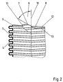
- Figure 2 shows the right end of the line element 1 according to Figure 1 again in a partial enlargement. It can also be seen there that the cutting line forming the end edge 12 can be accompanied by a previously produced stitch seam 13 from welding points.
- the line element according to FIGS. 1 and 2 is axially compressed at its ends after the separation in order to give it end planes 14, 15 which are located transversely to the axis 10 of the line element.
- one or more shafts 2 can be fully or partially detected by the upsetting process, so that at the ends of the Pipe element sufficient material is available for welding to further components. In the simplest case, it may be sufficient to carry out the compression only for the area around the positions 7 and 8.
Landscapes
- Engineering & Computer Science (AREA)
- General Engineering & Computer Science (AREA)
- Mechanical Engineering (AREA)
- Rigid Pipes And Flexible Pipes (AREA)
- Laser Beam Processing (AREA)
Applications Claiming Priority (2)
| Application Number | Priority Date | Filing Date | Title |
|---|---|---|---|
| DE4439218A DE4439218A1 (de) | 1994-11-03 | 1994-11-03 | Anschlußende eines Leitungselementes |
| DE4439218 | 1994-11-03 |
Publications (3)
| Publication Number | Publication Date |
|---|---|
| EP0713041A2 EP0713041A2 (de) | 1996-05-22 |
| EP0713041A3 EP0713041A3 (2) | 1996-06-26 |
| EP0713041B1 true EP0713041B1 (de) | 1997-12-29 |
Family
ID=6532364
Family Applications (1)
| Application Number | Title | Priority Date | Filing Date |
|---|---|---|---|
| EP95115671A Expired - Lifetime EP0713041B1 (de) | 1994-11-03 | 1995-10-05 | Anschlussende eines Leitungselementes |
Country Status (2)
| Country | Link |
|---|---|
| EP (1) | EP0713041B1 (2) |
| DE (2) | DE4439218A1 (2) |
Families Citing this family (2)
| Publication number | Priority date | Publication date | Assignee | Title |
|---|---|---|---|---|
| DE102012214044A1 (de) * | 2012-08-08 | 2014-05-22 | Witzenmann Gmbh | Verfahren und Vorrichtung zum Trennen von Wickelschläuchen |
| DE102013105678B4 (de) | 2013-06-03 | 2023-07-27 | Witzenmann Gmbh | Verfahren zum Trennen von Wickelschläuchen |
Family Cites Families (4)
| Publication number | Priority date | Publication date | Assignee | Title |
|---|---|---|---|---|
| US4063355A (en) * | 1976-08-30 | 1977-12-20 | I-T-E Imperial Corporation | Cutter for helically corrugated tube for flexible gas insulated cable |
| DE2645946C2 (de) * | 1976-10-12 | 1982-08-19 | Witzenmann GmbH, Metallschlauch-Fabrik Pforzheim, 7530 Pforzheim | Mehrlagiges Wellrohr für Abgasleitungen von Brennkraftmaschinen |
| DE3329178A1 (de) * | 1983-08-12 | 1985-02-21 | Felten & Guilleaume Energietechnik GmbH, 5000 Köln | Abmantelungs- und trennvorrichtung fuer ringfoermig gewellte fernwaermerohre |
| DE9406824U1 (de) * | 1994-03-31 | 1994-06-16 | Witzenmann GmbH, Metallschlauch-Fabrik Pforzheim, 75175 Pforzheim | Anschlußende für Wickelschläuche |
-
1994
- 1994-11-03 DE DE4439218A patent/DE4439218A1/de not_active Withdrawn
-
1995
- 1995-10-05 EP EP95115671A patent/EP0713041B1/de not_active Expired - Lifetime
- 1995-10-05 DE DE59501166T patent/DE59501166D1/de not_active Expired - Lifetime
Also Published As
| Publication number | Publication date |
|---|---|
| DE4439218A1 (de) | 1996-05-09 |
| EP0713041A3 (2) | 1996-06-26 |
| EP0713041A2 (de) | 1996-05-22 |
| DE59501166D1 (de) | 1998-02-05 |
Similar Documents
| Publication | Publication Date | Title |
|---|---|---|
| DE2827188C2 (de) | Bohrlochsieb | |
| DE69706275T2 (de) | Verfahren zur Herstellung eines Leitrohrs für einen Kernreaktor-brennstabbündel, Formdorn für ein derartiges Leitrohr und dadurch hergestelltes Leitrohr | |
| DE3315217A1 (de) | Schachtsieb mit verbindungsstueck und verfahren zu deren herstellung | |
| DE2806538A1 (de) | Verfahren zur herstellung einer kette von tueten | |
| DE2541257A1 (de) | Verfahren zum schweissen von rohren | |
| DE3420740A1 (de) | Drahtseil fuer die uebertragung eines drehmomentes | |
| DE1944587B2 (de) | Grossrohr mit schraubengangfoermig gewickelter mehrschich tiger wandlung und verfahren zu seiner herstellung | |
| EP0713041B1 (de) | Anschlussende eines Leitungselementes | |
| EP0674964B1 (de) | Verfahren zur Herstellung eines Anschlussendes für Wickelschläuche | |
| DE2853912A1 (de) | Abgasleitung fuer eine brennkraftmaschine | |
| EP0995352A1 (de) | Konditionierwalze und Verfahren zu deren Herstellung für Feldhäcksler | |
| DE2548853B2 (de) | Vorrichtung zur Herstellung von metallenen Ringrohlingen | |
| CH649013A5 (de) | Vorrichtung zum wellen von rohren. | |
| DE3825739A1 (de) | Verfahren zum herstellen von aufloesewalzenringen | |
| EP0182001B1 (de) | Verfahren und Vorrichtung zum Herstellen eines flexiblen Wellrohres sowie nach dem Verfahren hergestelltes flexibles Wellrohr | |
| DE2540273A1 (de) | Mehrlagiger wellschlauch | |
| DE4317333A1 (de) | Vorrichtung zum Dämpfen von Schwingungen in Abgasleitungen von Kraftfahrzeugen | |
| DE69907051T2 (de) | Flexibler Metallschlauch mit laminarer Strömung und Verfahren zu seiner Herstellung | |
| DE69807381T2 (de) | Verfahren zum Schneiden eines Rohrendes und zum Schweissen dieses Rohrendes an einem Werkstück | |
| DE2660703C2 (de) | Wellrohr für Lüftungsanlagen | |
| WO2020156783A1 (de) | Schraubennahtrohr sowie verfahren zur herstellung eines schraubennahtrohrs | |
| DE1807913A1 (de) | Sieb- oder Filterkoerper und Verfahren zu seiner Herstellung | |
| DE3541113C2 (2) | ||
| DE2406710A1 (de) | Verfahren zur herstellung von rohren mit polygonalem querschnitt und vorrichtung zur durchfuehrung des verfahrens | |
| DE1100118B (de) | Verfahren zur Herstellung von koaxialen Hochfrequenzleitungen und elektrischen Kabeln mit einem gerillten Aussenleiter bzw. metallenen Kabelmantel |
Legal Events
| Date | Code | Title | Description |
|---|---|---|---|
| PUAI | Public reference made under article 153(3) epc to a published international application that has entered the european phase |
Free format text: ORIGINAL CODE: 0009012 |
|
| PUAL | Search report despatched |
Free format text: ORIGINAL CODE: 0009013 |
|
| AK | Designated contracting states |
Kind code of ref document: A2 Designated state(s): DE FR GB IT |
|
| AK | Designated contracting states |
Kind code of ref document: A3 Designated state(s): DE FR GB IT |
|
| 17P | Request for examination filed |
Effective date: 19960529 |
|
| GRAG | Despatch of communication of intention to grant |
Free format text: ORIGINAL CODE: EPIDOS AGRA |
|
| 17Q | First examination report despatched |
Effective date: 19970502 |
|
| GRAG | Despatch of communication of intention to grant |
Free format text: ORIGINAL CODE: EPIDOS AGRA |
|
| GRAH | Despatch of communication of intention to grant a patent |
Free format text: ORIGINAL CODE: EPIDOS IGRA |
|
| GRAH | Despatch of communication of intention to grant a patent |
Free format text: ORIGINAL CODE: EPIDOS IGRA |
|
| GRAA | (expected) grant |
Free format text: ORIGINAL CODE: 0009210 |
|
| AK | Designated contracting states |
Kind code of ref document: B1 Designated state(s): DE FR GB IT |
|
| ITF | It: translation for a ep patent filed | ||
| GBT | Gb: translation of ep patent filed (gb section 77(6)(a)/1977) |
Effective date: 19971229 |
|
| REF | Corresponds to: |
Ref document number: 59501166 Country of ref document: DE Date of ref document: 19980205 |
|
| ET | Fr: translation filed | ||
| PLBE | No opposition filed within time limit |
Free format text: ORIGINAL CODE: 0009261 |
|
| STAA | Information on the status of an ep patent application or granted ep patent |
Free format text: STATUS: NO OPPOSITION FILED WITHIN TIME LIMIT |
|
| 26N | No opposition filed | ||
| REG | Reference to a national code |
Ref country code: GB Ref legal event code: IF02 |
|
| PGFP | Annual fee paid to national office [announced via postgrant information from national office to epo] |
Ref country code: GB Payment date: 20081024 Year of fee payment: 14 |
|
| PG25 | Lapsed in a contracting state [announced via postgrant information from national office to epo] |
Ref country code: GB Free format text: LAPSE BECAUSE OF NON-PAYMENT OF DUE FEES Effective date: 20091005 |
|
| PGFP | Annual fee paid to national office [announced via postgrant information from national office to epo] |
Ref country code: FR Payment date: 20111103 Year of fee payment: 17 |
|
| REG | Reference to a national code |
Ref country code: FR Ref legal event code: ST Effective date: 20130628 |
|
| PG25 | Lapsed in a contracting state [announced via postgrant information from national office to epo] |
Ref country code: FR Free format text: LAPSE BECAUSE OF NON-PAYMENT OF DUE FEES Effective date: 20121031 |
|
| PGFP | Annual fee paid to national office [announced via postgrant information from national office to epo] |
Ref country code: DE Payment date: 20141027 Year of fee payment: 20 |
|
| PGFP | Annual fee paid to national office [announced via postgrant information from national office to epo] |
Ref country code: IT Payment date: 20141029 Year of fee payment: 20 |
|
| REG | Reference to a national code |
Ref country code: DE Ref legal event code: R071 Ref document number: 59501166 Country of ref document: DE |