EP0710596B1 - Vorrichtung zum An- und Abkuppeln von Förderelementen bezüglich eines Antriebsmechanismus - Google Patents
Vorrichtung zum An- und Abkuppeln von Förderelementen bezüglich eines Antriebsmechanismus Download PDFInfo
- Publication number
- EP0710596B1 EP0710596B1 EP95202795A EP95202795A EP0710596B1 EP 0710596 B1 EP0710596 B1 EP 0710596B1 EP 95202795 A EP95202795 A EP 95202795A EP 95202795 A EP95202795 A EP 95202795A EP 0710596 B1 EP0710596 B1 EP 0710596B1
- Authority
- EP
- European Patent Office
- Prior art keywords
- rotatable element
- connection
- coupling bar
- stop
- conveyor
- Prior art date
- Legal status (The legal status is an assumption and is not a legal conclusion. Google has not performed a legal analysis and makes no representation as to the accuracy of the status listed.)
- Expired - Lifetime
Links
- 230000008878 coupling Effects 0.000 title claims abstract description 31
- 238000010168 coupling process Methods 0.000 title claims abstract description 31
- 238000005859 coupling reaction Methods 0.000 title claims abstract description 31
- 230000007246 mechanism Effects 0.000 title claims abstract description 16
- 230000006835 compression Effects 0.000 claims description 8
- 238000007906 compression Methods 0.000 claims description 8
- 238000004904 shortening Methods 0.000 claims description 2
- 230000033001 locomotion Effects 0.000 description 5
- 230000002159 abnormal effect Effects 0.000 description 1
- 230000005540 biological transmission Effects 0.000 description 1
Images

Classifications
-
- B—PERFORMING OPERATIONS; TRANSPORTING
- B61—RAILWAYS
- B61B—RAILWAY SYSTEMS; EQUIPMENT THEREFOR NOT OTHERWISE PROVIDED FOR
- B61B10/00—Power and free systems
- B61B10/02—Power and free systems with suspended vehicles
- B61B10/025—Coupling and uncoupling means between power track abd vehicles
-
- B—PERFORMING OPERATIONS; TRANSPORTING
- B61—RAILWAYS
- B61B—RAILWAY SYSTEMS; EQUIPMENT THEREFOR NOT OTHERWISE PROVIDED FOR
- B61B10/00—Power and free systems
- B61B10/04—Power and free systems with vehicles rolling trackless on the ground
Definitions
- This invention concerns a device for coupling and/or uncoupling conveyor elements in relation to a driving mechanism.
- the invention concerns driving mechanisms which mainly consist of a continuously moving driving element, such as an endless drag chain and conveyor elements, which usually consist of trolleys, and which are coupled to such a drag chain by means of a coupling part provided onto it, such as a drag pin, which works in conjunction with the driving element.
- a continuously moving driving element such as an endless drag chain and conveyor elements, which usually consist of trolleys, and which are coupled to such a drag chain by means of a coupling part provided onto it, such as a drag pin, which works in conjunction with the driving element.
- the known devices are disadvantageous in that they are easily damaged. This damage is caused when the above-mentioned rotatable element jams and the driving element continuous to exert a force on it, whereby either parts break off, or gears are damaged, or also the driving element is put out of order.
- the invention aims to provide a solution to this.
- the invention concerns a device for coupling and/or uncoupling conveyor elements in relation to a driving mechanism, consisting of a rotatable element in which is provided a guide for a drag pin of a conveyor element, and driving means to rotate the rotatable element, such that a conveyor element, as a result of the rotation of the rotatable element and by putting it in a given angular position, can be uncoupled from and/or coupled to the driving mechanism, characterized in that means are provided between the driving means and the rotatable element which can give way when the rotatable element jams.
- connection can give way should the rotatable element jam, and the driving means can continue to function normally without being excessively loaded, such that any damage to these driving means is excluded.
- the above-mentioned means consist of an elastic, deformable connection.
- the connection hereby preferably offers some initial resistance against the deformation, which is so great that a deformation only occurs when there is a jam.
- connection will consist of axially slidable parts in between which are provided springs.
- connection can be provided with a spring which allows at least for an extension of the connection. According to a variant, it can be provided with a spring which allows at least for a shortening of the connection.
- the device will be designed double-acting, such that the connection can give way in both directions, in other words such that it can both be elongated and compressed under a normal load.
- the invention is especially useful in the case of a positive drive, such as a drive by means of an electric motor.
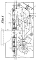
- the invention concerns a device 1 for uncoupling and/or coupling conveyor elements 2, such as a trolley, in relation to a driving mechanism, in particular a driving element 3 thereof, such as a drag chain.
- the conveyor element 2 can hereby be moved by means of a drag pin 4 or such.
- the drag pin 4 can hereby be taken along by a protrusion 5 provided on the driving element 3.
- the above-mentioned device 1 for coupling and/or uncoupling the conveyor elements 2 in relation to the driving element 3 consists of a rotatable element 6 in which is provided a guide 7 for a drag pin 4 of a conveyor element 2 and driving means 8 to rotate the rotatable element 6, such that a conveyor element 2 can be uncoupled from and/or coupled to the driving element 3 by turning the rotatable element 6 and by putting it in a given angular position.
- the rotatable element 6 can have various forms, but it preferably consists of a disc which can rotate around a pivot 9, whereas the guide 7 provided in it consists of a recess which is confined by two guiding edges 10 and 11.
- the guiding edge 10 stretches such that the drag pin 4 of an approaching conveyor element 2 is guided outside the path of the driving element 3 according to the course X represented in figure 2.
- the above-mentioned driving means 8 consist of an electric motor 13 and a crank mechanism 14 which is driven by the motor 13 and which converts the rotating movement R in a to and fro rocking motion T of the rotatable element 6.
- This crank mechanism 14 may for example consist of a crank rotating around a pivot 15, in the shape of a disc 16 which is driven by the motor 13 via a gear transmission 17, and a connecting rod 18 which is connected to the disc 16 by means of a pivot 19 on the one hand, and which is connected to the rotatable element 6 by means of a pivot 20 on the other hand.
- means 21 are provided between the driving means 8 and the rotatable element 6 which can give way when the rotatable element 6 jams.
- these means 21 are part of the above-mentioned connecting rod 18. It is clear, however, that these means 21 can also be provided in another place.
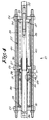
- these means 21 preferably consist of an elastic, deformable connection, in this case between the pivots 19 and 20, which is designed such that it offers some initial resistance against deformation, so that when the device 1 functions normally, there is no or almost no deformation and the distance between the pivots 19 and 20 remains unaltered, but when the rotatable element 6 jams, the connection can be elastically elongated and/or compressed, such that the driving means 8 can carry out a normal working cycle.
- the above-mentioned elastic, deformable connection preferably consists of a cylinder 22 with two end walls 23 and 24 and a dividing wall 25; a first coupling bar 26 which can be moved in the cylinder 22, which goes through the first end wall 23 and which is coupled to the driving means 8, whereby this coupling bar 26 is provided with a stop 27 which cooperates with a first side 28 of the dividing wall 25, whereby this stop 27 prevents the first coupling bar 26 from being pushed in the cylinder 22; a first compression spring 29 which is provided between the inside 30 of the first end wall 23 and a stop 31 on the first coupling bar 26; a second coupling bar 32 which can be moved in the cylinder 22 which goes through the second end wall 24 and which is connected to the rotatable element 6, whereby this coupling bar 32 is provided with a stop 33 which cooperates with the inside 34 of the second end wall 24, whereby this stop 33 prevents the second coupling bar 32 from sliding out of the cylinder 22; and a second compression spring 35 which is provided
- the cylinder 22 is preferably composed of two cylinder parts 38 and 39 which are respectively provided between the end wall 23 and the dividing wall 25 on the one hand, and between the dividing wall 25 and the end wall 24 on the other hand, whereby the whole is held together by means of rods 40 which go through the walls 23, 24 and 25.
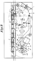
- the device 1 can possibly be equipped with a mechanical interlock 41 which can interlock the rotatable element 6 in the above-mentioned position A in order to prevent the element 6 from turning when a drag pin 4 slides along the guiding edge 10.
- This interlock 41 preferably consists of a rotatable arm 42 with a first pawl 43 which can mesh in a recess 44 in the rotatable element 6 and a second pawl 45 which cooperates with the perimeter of a disc driven by the motor 13, in this case the above-mentioned disc 16, and which takes place in a recess 46 on the perimeter of this disc 16, whereby the interlock 41 is switched on when the second pawl 45 moves in the recess 46 of the disc 16.
- the arm 42 is hereby forced into one direction by means of a spring 47.
- the above-mentioned connection is hereby provided with a play 48 which allows for a rotation of the disc 16 over a small angle without the rotatable element 6 being moved, whereby this play 48 is so large that the interlock can be uncoupled during this rotation.
- this play 48 can be obtained by using such a compression spring 29 or by mounting this compression spring 29 such that it allows for a free movement of the first coupling bar 26 in relation to the cylinder 22 over a certain distance D.
- a slidable connecting piece 49 which retains the compression spring 29 and which is provided with a stop 50 which can cooperate with the stop 31.
- the first coupling bar 26 can hereby move freely between a position in which the stop 27 makes contact with the side 28 and a position in which the stop 31 acts on the compression spring 29 through the intervention of the connecting piece 49.
- the device 1 can be equipped with additional accessories.
- a guide 54 which can be moved against the force of a spring 53 which makes sure that the conveyor element 2 is gradually slowed down via the drag pin 4 when it is uncoupled from the driving element 3.
- the rotatable element 6 When an approaching conveyor element 2 must be uncoupled, the rotatable element 6 is maintained in the rest position A.
- the drag pin 4 which is taken along by the drag chain then makes contact with the guiding edge 10 and is forced in the guide 7 as represented in figure 2.
- the drag pin 4 As the drag pin 4 is situated outside the path of the drag chain, in particular of the protrusions 5, the drag movement is interrupted and the conveyor element comes to a standstill.
- crank mechanism 4 In order to drag the conveyor element 2, the crank mechanism 4 is moved to and from over one cycle by making the disc 16, via the control of the motor 13, make one rotation.
- the first coupling bar 26 of figure 4 is shifted to the left, over the distance D, without following the cylinder 22 and the second coupling bar 32.
- the rotatable element 6 keeps standing still during this movement.
- the pawl 45 is forced out of the recess 46, the interlocking 41 comes loose.
- the short standstill of the rotatable element 6 makes it possible to freely take the pawl 43 out of the recess 44.
- the position of the figures 1 and 2 preferably forms the rest position, but that this is not necessarily so.
- the motor 13 can be controlled in various manners. According to one possibility, use can be made of a servomotor which each time carries out a specific rotation. According to another possibility, an interruption contact can be provided on the arm 42.
Landscapes
- Engineering & Computer Science (AREA)
- Transportation (AREA)
- Mechanical Engineering (AREA)
- Transmission Devices (AREA)
- Intermediate Stations On Conveyors (AREA)
- Gear Transmission (AREA)
- Flanged Joints, Insulating Joints, And Other Joints (AREA)
- Delivering By Means Of Belts And Rollers (AREA)
- Attitude Control For Articles On Conveyors (AREA)
Claims (10)
- Vorrichtung zum Ankuppeln und/oder Abkuppeln von Förderelementen bezüglich eines Antriebsmechanismus, bestehend aus einem drehbaren Element (6), worin eine Führung (7) für einen Mitnehmerzapfen (4) eines Förderelements (2) angebracht ist, und Antriebsmittel (8) zum Verdrehen des drehbaren Elements (6), derart, daß ein Förderelement (2), als Resultat der Verdrehung des drehbaren Elements (6) und indem es in eine vorgegebene Winkelposition versetzt wird, von dem Antriebsmechanismus abgekuppelt und/oder damit gekuppelt werden kann, dadurch gekennzeichnet, daß Mittel (21) zwischen den Antriebsmitteln (8) und dem drehbaren Element (6) vorgesehen sind, die nachgeben können, wenn das drehbare Element (6) festläuft.
- Vorrichtung gemäß Anspruch 1, dadurch gekennzeichnet, daß die oben erwähnten Mittel (21) aus einer elastischen, verformbaren Verbindung bestehen.
- Vorrichtung gemäß Anspruch 2, dadurch gekennzeichnet, daß die Verbindung der Verformung einen Anfangswiderstand entgegensetzt, der so groß ist, daß eine Verformung nur stattfindet, wenn ein Festlaufen vorliegt.
- Vorrichtung gemäß Anspruch 2 oder 3, dadurch gekennzeichnet, daß die oben erwähnte Verbindung aus axial verschiebbaren Teilen besteht, zwischen denen Federn (29-35) vorgesehen sind.
- Vorrichtung gemäß Anspruch 4, dadurch gekennzeichnet, daß die oben erwähnte Verbindung zumindest mit einer Feder (29) versehen ist, die eine Verlängerung der Verbindung gestattet.
- Vorrichtung gemäß Anspruch 4 oder 5, dadurch gekennzeichnet, daß die oben erwähnte Verbindung zumindest mit einer Feder (35) versehen ist, die ein Verkürzen der Verbindung gestattet.
- Vorrichtung gemäß Anspruch 4, 5 oder 6, dadurch gekennzeichnet, daß die Verbindung hauptsächlich aus einem Zylinder (22) mit zwei Endwänden (23-24) und einer Zwischenwand (25) besteht; einer ersten, im Zylinder (22) bewegbaren Kupplungsstange (26), die durch die erste Endwand (23) geht und die mit den Antriebsmitteln (8) gekuppelt ist, wobei diese Kupplungsstange (26) mit einem Anschlag (27) versehen ist, der mit einer ersten Seite (28) der Zwischenwand (25) zusammenwirkt, wobei dieser Anschlag (27) das Eindrücken der ersten Kupplungsstange (26) in den Zylinder (22) verhindert; einer ersten Druckfeder (29), die zwischen der Innenseite (30) der ersten Endwand (23) und einem Anschlag (31) auf der ersten Kupplungsstange (26) vorgesehen ist; einer zweiten, im Zylinder (22) bewegbaren Kupplungsstange (32), die durch die zweite Endwand (24) geht und die mit dem drehbaren Element (6) verbunden ist, wobei diese Kupplungsstange (32) mit einem Anschlag (33) versehen ist, der mit der zweiten Endwand (24) zusammenwirkt, wobei dieser Anschlag (33) das Herausschieben der zweiten Kupplungsstange (32) aus dem Zylinder (22) verhindert; und einer zweiten Druckfeder (35), die zwischen der zweiten Seite (36) der Zwischenwand (25) und einem Anschlag (37) auf der zweiten Kupplungsstange (32) vorgesehen ist.
- Vorrichtung gemäß einem der vorangehenden Ansprüche, dadurch gekennzeichnet, daß die Antriebsmittel (8) einen Elektromotor (13) verwenden.
- Vorrichtung gemäß Anspruch 8 und einem der Ansprüche 2 bis 7, dadurch gekennzeichnet, daß die oben erwähnte Verbindung Teil einer Kurbelstange (18) zwischen einer vom Motor (13) angetriebenen Kurbel und dem oben erwähnten drehbaren Element (6) ist.
- Vorrichtung gemäß Anspruch 9, dadurch gekennzeichnet, daß sie mit einer mechanischen Verriegelung (41) versehen ist, die das drehbare Element (6) in der Position (A) verriegeln kann, wobei ein Förderelement (2) zum Stillstand gebracht wird; dadurch, daß diese Verriegelung (41) aus einem drehbaren Arm (42) mit einer ersten Sperrklinke (43), die in eine Aussparung (44) im drehbaren Element (6) eingreifen kann, besteht, und einer zweiten Sperrklinke (45), die mit dem Umfang einer vom Motor (13) angetriebenen Scheibe (16) zusammenwirkt und die sich in eine Aussparung (46) auf dem Umfang dieser Scheibe (16) einpassen kann, wobei die Verriegelung (41) eingeschaltet wird, wenn die zweite Sperrklinke (45) sich in die Aussparung (46) der Scheibe (16) bewegt; und dadurch, daß die Verbindung mit einem Spiel (48) versehen ist, das ein Verdrehen der Scheibe (16) über einen kleinen Winkel gestattet, ohne daß das drehbare Element (6) bewegt wird, wobei dieses Spiel (48) so groß ist, daß die Verriegelung (41) während dieses Verdrehens ausgekuppelt wird.
Applications Claiming Priority (2)
| Application Number | Priority Date | Filing Date | Title |
|---|---|---|---|
| BE9400999A BE1008851A3 (nl) | 1994-11-03 | 1994-11-03 | Inrichting voor het ontkoppelen en/of koppelen van transportelementen t.o.v. een aandrijfmechanisme. |
| BE9400999 | 1994-11-03 |
Publications (2)
| Publication Number | Publication Date |
|---|---|
| EP0710596A1 EP0710596A1 (de) | 1996-05-08 |
| EP0710596B1 true EP0710596B1 (de) | 1999-07-28 |
Family
ID=3888457
Family Applications (1)
| Application Number | Title | Priority Date | Filing Date |
|---|---|---|---|
| EP95202795A Expired - Lifetime EP0710596B1 (de) | 1994-11-03 | 1995-10-17 | Vorrichtung zum An- und Abkuppeln von Förderelementen bezüglich eines Antriebsmechanismus |
Country Status (9)
| Country | Link |
|---|---|
| EP (1) | EP0710596B1 (de) |
| JP (1) | JPH08208018A (de) |
| AT (1) | ATE182532T1 (de) |
| AU (1) | AU688124B2 (de) |
| BE (1) | BE1008851A3 (de) |
| CZ (1) | CZ285995A3 (de) |
| DE (1) | DE69511041T2 (de) |
| HU (1) | HUT72998A (de) |
| PL (1) | PL311220A1 (de) |
Families Citing this family (1)
| Publication number | Priority date | Publication date | Assignee | Title |
|---|---|---|---|---|
| WO2011108071A1 (ja) * | 2010-03-02 | 2011-09-09 | メタルエンジニアリング株式会社 | 台車搬送装置 |
Family Cites Families (5)
| Publication number | Priority date | Publication date | Assignee | Title |
|---|---|---|---|---|
| US3648618A (en) * | 1970-03-09 | 1972-03-14 | Cutler Hammer Inc | Subfloor conveyor system and dolly therefor |
| US3796915A (en) * | 1970-10-16 | 1974-03-12 | Agfa Gevaert Ag | Illumination installation |
| US4020768A (en) * | 1975-07-21 | 1977-05-03 | Si Handling Systems, Inc. | Tow line accumulator |
| JPH05259478A (ja) * | 1992-03-12 | 1993-10-08 | Fuji Electric Co Ltd | 半導体圧力センサの製造方法 |
| BE1005998A3 (nl) * | 1992-06-18 | 1994-04-12 | Egemin Elekt Goeder Marine Ind | Werkwijze en inrichting voor het ontkoppelen en/of koppelen en/of gekoppeld houden van transportelementen aan een aandrijfmechanisme. |
-
1994
- 1994-11-03 BE BE9400999A patent/BE1008851A3/nl not_active IP Right Cessation
-
1995
- 1995-10-17 DE DE69511041T patent/DE69511041T2/de not_active Expired - Fee Related
- 1995-10-17 EP EP95202795A patent/EP0710596B1/de not_active Expired - Lifetime
- 1995-10-17 AT AT95202795T patent/ATE182532T1/de not_active IP Right Cessation
- 1995-10-24 AU AU34434/95A patent/AU688124B2/en not_active Ceased
- 1995-10-27 JP JP7280507A patent/JPH08208018A/ja active Pending
- 1995-10-30 HU HU9503097A patent/HUT72998A/hu unknown
- 1995-11-01 CZ CZ952859A patent/CZ285995A3/cs unknown
- 1995-11-02 PL PL95311220A patent/PL311220A1/xx unknown
Also Published As
| Publication number | Publication date |
|---|---|
| AU688124B2 (en) | 1998-03-05 |
| DE69511041T2 (de) | 1999-12-30 |
| HU9503097D0 (en) | 1995-12-28 |
| AU3443495A (en) | 1996-05-09 |
| DE69511041D1 (de) | 1999-09-02 |
| JPH08208018A (ja) | 1996-08-13 |
| EP0710596A1 (de) | 1996-05-08 |
| PL311220A1 (en) | 1996-05-13 |
| BE1008851A3 (nl) | 1996-08-06 |
| CZ285995A3 (en) | 1996-07-17 |
| HUT72998A (en) | 1996-06-28 |
| ATE182532T1 (de) | 1999-08-15 |
Similar Documents
| Publication | Publication Date | Title |
|---|---|---|
| US4267875A (en) | Sliding clutch for venetian blind | |
| FI79986C (fi) | Kollisionsskyddsanordning foer fabriksinterna transportfordon. | |
| CN101425401B (zh) | 装备有螺旋弹簧型机械制动器的电动机械致动器 | |
| US5275250A (en) | Vehicle steering control device | |
| SU1524811A3 (ru) | Устройство дл соединени ремизных рам ремизоподъемного механизма ткацкого станка с ремизоподъемной кареткой | |
| EP0710596B1 (de) | Vorrichtung zum An- und Abkuppeln von Förderelementen bezüglich eines Antriebsmechanismus | |
| DK173190B1 (da) | Fremgangsmåde og apparat til tryk- og /eller trækkraftoverføring | |
| US5406750A (en) | Chain operator for windows | |
| JP3824381B2 (ja) | セーフティースイッチ | |
| US6247580B1 (en) | Actuator for a bi-directional conveyor belt | |
| US4294553A (en) | Ribbon feed mechanism | |
| CN112943027A (zh) | 具有防夹手功能的开关装置及舱体 | |
| US5954108A (en) | Drive unit for a vertical blind | |
| KR102168537B1 (ko) | 개스스프링과 움직도르래를 이용한 반자동식 슬라이딩 도어 | |
| EP4524434A1 (de) | Parkvorrichtung und parksystem für kraftfahrzeug und kraftfahrzeug | |
| US5050644A (en) | Coupling arrangement for a loom harness shaft | |
| KR100916081B1 (ko) | 가역벨트의 진행방향에 따른 크리너 선택장치 | |
| EP1413701B1 (de) | Sicherheitsvorrichtung für ein sektionales Schliesselement, z.B. Tür, Haupttür, Tor oder dergleichen | |
| ITMI941060A1 (it) | Dispositivo per l'azionamento automatico di un cavalletto | |
| SU1315698A1 (ru) | Кантователь | |
| EP1835104B1 (de) | Sicherheitsvorrichtung für ein sektionales Schliesselement, z.B. Tür, Haupttür, Tor oder dergleichen | |
| KR100661726B1 (ko) | 차량용 자동변속장치 | |
| CN112109114B (zh) | 一种开关门机构及机器人 | |
| JPS5919620Y2 (ja) | 変速連動装置における変速指示ア−ム | |
| SU1057270A1 (ru) | Головка схвата манипул тора |
Legal Events
| Date | Code | Title | Description |
|---|---|---|---|
| PUAI | Public reference made under article 153(3) epc to a published international application that has entered the european phase |
Free format text: ORIGINAL CODE: 0009012 |
|
| AK | Designated contracting states |
Kind code of ref document: A1 Designated state(s): AT CH DE DK ES FR GB GR IE IT LI LU MC NL PT SE |
|
| 17P | Request for examination filed |
Effective date: 19960523 |
|
| GRAG | Despatch of communication of intention to grant |
Free format text: ORIGINAL CODE: EPIDOS AGRA |
|
| 17Q | First examination report despatched |
Effective date: 19981001 |
|
| GRAG | Despatch of communication of intention to grant |
Free format text: ORIGINAL CODE: EPIDOS AGRA |
|
| GRAH | Despatch of communication of intention to grant a patent |
Free format text: ORIGINAL CODE: EPIDOS IGRA |
|
| GRAH | Despatch of communication of intention to grant a patent |
Free format text: ORIGINAL CODE: EPIDOS IGRA |
|
| GRAA | (expected) grant |
Free format text: ORIGINAL CODE: 0009210 |
|
| AK | Designated contracting states |
Kind code of ref document: B1 Designated state(s): AT CH DE DK ES FR GB GR IE IT LI LU MC NL PT SE |
|
| PG25 | Lapsed in a contracting state [announced via postgrant information from national office to epo] |
Ref country code: SE Free format text: LAPSE BECAUSE OF FAILURE TO SUBMIT A TRANSLATION OF THE DESCRIPTION OR TO PAY THE FEE WITHIN THE PRESCRIBED TIME-LIMIT Effective date: 19990728 Ref country code: NL Free format text: LAPSE BECAUSE OF FAILURE TO SUBMIT A TRANSLATION OF THE DESCRIPTION OR TO PAY THE FEE WITHIN THE PRESCRIBED TIME-LIMIT Effective date: 19990728 Ref country code: LI Free format text: LAPSE BECAUSE OF FAILURE TO SUBMIT A TRANSLATION OF THE DESCRIPTION OR TO PAY THE FEE WITHIN THE PRESCRIBED TIME-LIMIT Effective date: 19990728 Ref country code: IT Free format text: LAPSE BECAUSE OF FAILURE TO SUBMIT A TRANSLATION OF THE DESCRIPTION OR TO PAY THE FEE WITHIN THE PRE;WARNING: LAPSES OF ITALIAN PATENTS WITH EFFECTIVE DATE BEFORE 2007 MAY HAVE OCCURRED AT ANY TIME BEFORE 2007. THE CORRECT EFFECTIVE DATE MAY BE DIFFERENT FROM THE ONE RECORDED.SCRIBED TIME-LIMIT Effective date: 19990728 Ref country code: GR Free format text: LAPSE BECAUSE OF NON-PAYMENT OF DUE FEES Effective date: 19990728 Ref country code: FR Free format text: LAPSE BECAUSE OF FAILURE TO SUBMIT A TRANSLATION OF THE DESCRIPTION OR TO PAY THE FEE WITHIN THE PRESCRIBED TIME-LIMIT Effective date: 19990728 Ref country code: ES Free format text: THE PATENT HAS BEEN ANNULLED BY A DECISION OF A NATIONAL AUTHORITY Effective date: 19990728 Ref country code: CH Free format text: LAPSE BECAUSE OF FAILURE TO SUBMIT A TRANSLATION OF THE DESCRIPTION OR TO PAY THE FEE WITHIN THE PRESCRIBED TIME-LIMIT Effective date: 19990728 Ref country code: AT Free format text: LAPSE BECAUSE OF FAILURE TO SUBMIT A TRANSLATION OF THE DESCRIPTION OR TO PAY THE FEE WITHIN THE PRESCRIBED TIME-LIMIT Effective date: 19990728 |
|
| REF | Corresponds to: |
Ref document number: 182532 Country of ref document: AT Date of ref document: 19990815 Kind code of ref document: T |
|
| REG | Reference to a national code |
Ref country code: CH Ref legal event code: EP |
|
| REF | Corresponds to: |
Ref document number: 69511041 Country of ref document: DE Date of ref document: 19990902 |
|
| PGFP | Annual fee paid to national office [announced via postgrant information from national office to epo] |
Ref country code: SE Payment date: 19991004 Year of fee payment: 5 |
|
| REG | Reference to a national code |
Ref country code: IE Ref legal event code: FG4D |
|
| PGFP | Annual fee paid to national office [announced via postgrant information from national office to epo] |
Ref country code: NL Payment date: 19991026 Year of fee payment: 5 |
|
| PG25 | Lapsed in a contracting state [announced via postgrant information from national office to epo] |
Ref country code: PT Free format text: LAPSE BECAUSE OF FAILURE TO SUBMIT A TRANSLATION OF THE DESCRIPTION OR TO PAY THE FEE WITHIN THE PRESCRIBED TIME-LIMIT Effective date: 19991028 Ref country code: DK Free format text: LAPSE BECAUSE OF FAILURE TO SUBMIT A TRANSLATION OF THE DESCRIPTION OR TO PAY THE FEE WITHIN THE PRESCRIBED TIME-LIMIT Effective date: 19991028 |
|
| EN | Fr: translation not filed | ||
| NLV1 | Nl: lapsed or annulled due to failure to fulfill the requirements of art. 29p and 29m of the patents act | ||
| REG | Reference to a national code |
Ref country code: CH Ref legal event code: PL |
|
| PLBE | No opposition filed within time limit |
Free format text: ORIGINAL CODE: 0009261 |
|
| STAA | Information on the status of an ep patent application or granted ep patent |
Free format text: STATUS: NO OPPOSITION FILED WITHIN TIME LIMIT |
|
| 26N | No opposition filed | ||
| PGFP | Annual fee paid to national office [announced via postgrant information from national office to epo] |
Ref country code: LU Payment date: 20010918 Year of fee payment: 7 |
|
| PGFP | Annual fee paid to national office [announced via postgrant information from national office to epo] |
Ref country code: IE Payment date: 20010920 Year of fee payment: 7 |
|
| PGFP | Annual fee paid to national office [announced via postgrant information from national office to epo] |
Ref country code: MC Payment date: 20010925 Year of fee payment: 7 |
|
| PGFP | Annual fee paid to national office [announced via postgrant information from national office to epo] |
Ref country code: DE Payment date: 20011008 Year of fee payment: 7 |
|
| PGFP | Annual fee paid to national office [announced via postgrant information from national office to epo] |
Ref country code: GB Payment date: 20011016 Year of fee payment: 7 |
|
| REG | Reference to a national code |
Ref country code: GB Ref legal event code: IF02 |
|
| PG25 | Lapsed in a contracting state [announced via postgrant information from national office to epo] |
Ref country code: LU Free format text: LAPSE BECAUSE OF NON-PAYMENT OF DUE FEES Effective date: 20021017 Ref country code: IE Free format text: LAPSE BECAUSE OF NON-PAYMENT OF DUE FEES Effective date: 20021017 Ref country code: GB Free format text: LAPSE BECAUSE OF NON-PAYMENT OF DUE FEES Effective date: 20021017 |
|
| PG25 | Lapsed in a contracting state [announced via postgrant information from national office to epo] |
Ref country code: MC Free format text: LAPSE BECAUSE OF NON-PAYMENT OF DUE FEES Effective date: 20030501 Ref country code: DE Free format text: LAPSE BECAUSE OF NON-PAYMENT OF DUE FEES Effective date: 20030501 |
|
| GBPC | Gb: european patent ceased through non-payment of renewal fee |
Effective date: 20021017 |
|
| REG | Reference to a national code |
Ref country code: IE Ref legal event code: MM4A |