EP0710596B1 - Device for coupling and/or uncoupling conveyor elements in relation to a driving mechanism - Google Patents
Device for coupling and/or uncoupling conveyor elements in relation to a driving mechanism Download PDFInfo
- Publication number
- EP0710596B1 EP0710596B1 EP95202795A EP95202795A EP0710596B1 EP 0710596 B1 EP0710596 B1 EP 0710596B1 EP 95202795 A EP95202795 A EP 95202795A EP 95202795 A EP95202795 A EP 95202795A EP 0710596 B1 EP0710596 B1 EP 0710596B1
- Authority
- EP
- European Patent Office
- Prior art keywords
- rotatable element
- connection
- coupling bar
- stop
- conveyor
- Prior art date
- Legal status (The legal status is an assumption and is not a legal conclusion. Google has not performed a legal analysis and makes no representation as to the accuracy of the status listed.)
- Expired - Lifetime
Links
Images

Classifications
-
- B—PERFORMING OPERATIONS; TRANSPORTING
- B61—RAILWAYS
- B61B—RAILWAY SYSTEMS; EQUIPMENT THEREFOR NOT OTHERWISE PROVIDED FOR
- B61B10/00—Power and free systems
- B61B10/02—Power and free systems with suspended vehicles
- B61B10/025—Coupling and uncoupling means between power track abd vehicles
-
- B—PERFORMING OPERATIONS; TRANSPORTING
- B61—RAILWAYS
- B61B—RAILWAY SYSTEMS; EQUIPMENT THEREFOR NOT OTHERWISE PROVIDED FOR
- B61B10/00—Power and free systems
- B61B10/04—Power and free systems with vehicles rolling trackless on the ground
Definitions
- This invention concerns a device for coupling and/or uncoupling conveyor elements in relation to a driving mechanism.
- the invention concerns driving mechanisms which mainly consist of a continuously moving driving element, such as an endless drag chain and conveyor elements, which usually consist of trolleys, and which are coupled to such a drag chain by means of a coupling part provided onto it, such as a drag pin, which works in conjunction with the driving element.
- a continuously moving driving element such as an endless drag chain and conveyor elements, which usually consist of trolleys, and which are coupled to such a drag chain by means of a coupling part provided onto it, such as a drag pin, which works in conjunction with the driving element.
- the known devices are disadvantageous in that they are easily damaged. This damage is caused when the above-mentioned rotatable element jams and the driving element continuous to exert a force on it, whereby either parts break off, or gears are damaged, or also the driving element is put out of order.
- the invention aims to provide a solution to this.
- the invention concerns a device for coupling and/or uncoupling conveyor elements in relation to a driving mechanism, consisting of a rotatable element in which is provided a guide for a drag pin of a conveyor element, and driving means to rotate the rotatable element, such that a conveyor element, as a result of the rotation of the rotatable element and by putting it in a given angular position, can be uncoupled from and/or coupled to the driving mechanism, characterized in that means are provided between the driving means and the rotatable element which can give way when the rotatable element jams.
- connection can give way should the rotatable element jam, and the driving means can continue to function normally without being excessively loaded, such that any damage to these driving means is excluded.
- the above-mentioned means consist of an elastic, deformable connection.
- the connection hereby preferably offers some initial resistance against the deformation, which is so great that a deformation only occurs when there is a jam.
- connection will consist of axially slidable parts in between which are provided springs.
- connection can be provided with a spring which allows at least for an extension of the connection. According to a variant, it can be provided with a spring which allows at least for a shortening of the connection.
- the device will be designed double-acting, such that the connection can give way in both directions, in other words such that it can both be elongated and compressed under a normal load.
- the invention is especially useful in the case of a positive drive, such as a drive by means of an electric motor.
- the invention concerns a device 1 for uncoupling and/or coupling conveyor elements 2, such as a trolley, in relation to a driving mechanism, in particular a driving element 3 thereof, such as a drag chain.
- the conveyor element 2 can hereby be moved by means of a drag pin 4 or such.
- the drag pin 4 can hereby be taken along by a protrusion 5 provided on the driving element 3.
- the above-mentioned device 1 for coupling and/or uncoupling the conveyor elements 2 in relation to the driving element 3 consists of a rotatable element 6 in which is provided a guide 7 for a drag pin 4 of a conveyor element 2 and driving means 8 to rotate the rotatable element 6, such that a conveyor element 2 can be uncoupled from and/or coupled to the driving element 3 by turning the rotatable element 6 and by putting it in a given angular position.
- the rotatable element 6 can have various forms, but it preferably consists of a disc which can rotate around a pivot 9, whereas the guide 7 provided in it consists of a recess which is confined by two guiding edges 10 and 11.
- the guiding edge 10 stretches such that the drag pin 4 of an approaching conveyor element 2 is guided outside the path of the driving element 3 according to the course X represented in figure 2.
- the above-mentioned driving means 8 consist of an electric motor 13 and a crank mechanism 14 which is driven by the motor 13 and which converts the rotating movement R in a to and fro rocking motion T of the rotatable element 6.
- This crank mechanism 14 may for example consist of a crank rotating around a pivot 15, in the shape of a disc 16 which is driven by the motor 13 via a gear transmission 17, and a connecting rod 18 which is connected to the disc 16 by means of a pivot 19 on the one hand, and which is connected to the rotatable element 6 by means of a pivot 20 on the other hand.
- means 21 are provided between the driving means 8 and the rotatable element 6 which can give way when the rotatable element 6 jams.
- these means 21 are part of the above-mentioned connecting rod 18. It is clear, however, that these means 21 can also be provided in another place.
- these means 21 preferably consist of an elastic, deformable connection, in this case between the pivots 19 and 20, which is designed such that it offers some initial resistance against deformation, so that when the device 1 functions normally, there is no or almost no deformation and the distance between the pivots 19 and 20 remains unaltered, but when the rotatable element 6 jams, the connection can be elastically elongated and/or compressed, such that the driving means 8 can carry out a normal working cycle.
- the above-mentioned elastic, deformable connection preferably consists of a cylinder 22 with two end walls 23 and 24 and a dividing wall 25; a first coupling bar 26 which can be moved in the cylinder 22, which goes through the first end wall 23 and which is coupled to the driving means 8, whereby this coupling bar 26 is provided with a stop 27 which cooperates with a first side 28 of the dividing wall 25, whereby this stop 27 prevents the first coupling bar 26 from being pushed in the cylinder 22; a first compression spring 29 which is provided between the inside 30 of the first end wall 23 and a stop 31 on the first coupling bar 26; a second coupling bar 32 which can be moved in the cylinder 22 which goes through the second end wall 24 and which is connected to the rotatable element 6, whereby this coupling bar 32 is provided with a stop 33 which cooperates with the inside 34 of the second end wall 24, whereby this stop 33 prevents the second coupling bar 32 from sliding out of the cylinder 22; and a second compression spring 35 which is provided
- the cylinder 22 is preferably composed of two cylinder parts 38 and 39 which are respectively provided between the end wall 23 and the dividing wall 25 on the one hand, and between the dividing wall 25 and the end wall 24 on the other hand, whereby the whole is held together by means of rods 40 which go through the walls 23, 24 and 25.
- the device 1 can possibly be equipped with a mechanical interlock 41 which can interlock the rotatable element 6 in the above-mentioned position A in order to prevent the element 6 from turning when a drag pin 4 slides along the guiding edge 10.
- This interlock 41 preferably consists of a rotatable arm 42 with a first pawl 43 which can mesh in a recess 44 in the rotatable element 6 and a second pawl 45 which cooperates with the perimeter of a disc driven by the motor 13, in this case the above-mentioned disc 16, and which takes place in a recess 46 on the perimeter of this disc 16, whereby the interlock 41 is switched on when the second pawl 45 moves in the recess 46 of the disc 16.
- the arm 42 is hereby forced into one direction by means of a spring 47.
- the above-mentioned connection is hereby provided with a play 48 which allows for a rotation of the disc 16 over a small angle without the rotatable element 6 being moved, whereby this play 48 is so large that the interlock can be uncoupled during this rotation.
- this play 48 can be obtained by using such a compression spring 29 or by mounting this compression spring 29 such that it allows for a free movement of the first coupling bar 26 in relation to the cylinder 22 over a certain distance D.
- a slidable connecting piece 49 which retains the compression spring 29 and which is provided with a stop 50 which can cooperate with the stop 31.
- the first coupling bar 26 can hereby move freely between a position in which the stop 27 makes contact with the side 28 and a position in which the stop 31 acts on the compression spring 29 through the intervention of the connecting piece 49.
- the device 1 can be equipped with additional accessories.
- a guide 54 which can be moved against the force of a spring 53 which makes sure that the conveyor element 2 is gradually slowed down via the drag pin 4 when it is uncoupled from the driving element 3.
- the rotatable element 6 When an approaching conveyor element 2 must be uncoupled, the rotatable element 6 is maintained in the rest position A.
- the drag pin 4 which is taken along by the drag chain then makes contact with the guiding edge 10 and is forced in the guide 7 as represented in figure 2.
- the drag pin 4 As the drag pin 4 is situated outside the path of the drag chain, in particular of the protrusions 5, the drag movement is interrupted and the conveyor element comes to a standstill.
- crank mechanism 4 In order to drag the conveyor element 2, the crank mechanism 4 is moved to and from over one cycle by making the disc 16, via the control of the motor 13, make one rotation.
- the first coupling bar 26 of figure 4 is shifted to the left, over the distance D, without following the cylinder 22 and the second coupling bar 32.
- the rotatable element 6 keeps standing still during this movement.
- the pawl 45 is forced out of the recess 46, the interlocking 41 comes loose.
- the short standstill of the rotatable element 6 makes it possible to freely take the pawl 43 out of the recess 44.
- the position of the figures 1 and 2 preferably forms the rest position, but that this is not necessarily so.
- the motor 13 can be controlled in various manners. According to one possibility, use can be made of a servomotor which each time carries out a specific rotation. According to another possibility, an interruption contact can be provided on the arm 42.
Landscapes
- Engineering & Computer Science (AREA)
- Transportation (AREA)
- Mechanical Engineering (AREA)
- Transmission Devices (AREA)
- Intermediate Stations On Conveyors (AREA)
- Attitude Control For Articles On Conveyors (AREA)
- Gear Transmission (AREA)
- Flanged Joints, Insulating Joints, And Other Joints (AREA)
- Delivering By Means Of Belts And Rollers (AREA)
Abstract
Description
- This invention concerns a device for coupling and/or uncoupling conveyor elements in relation to a driving mechanism.
- In particular, the invention concerns driving mechanisms which mainly consist of a continuously moving driving element, such as an endless drag chain and conveyor elements, which usually consist of trolleys, and which are coupled to such a drag chain by means of a coupling part provided onto it, such as a drag pin, which works in conjunction with the driving element.
It is known that for coupling and/or uncoupling conveyor elements in relation to the driving mechanism, use can be made of an element which can be rotated by means of driving means in which is provided a guide for a drag pin of a conveyor element, such that a conveyor element, due to the rotation of the rotatable element so as to place it in a given angular position, can be uncoupled from and/or coupled to the drag device, as the drag pin is either put out of the path followed by the driving mechanism, or is put back into this path by means of the above-mentioned guide. - However, the known devices are disadvantageous in that they are easily damaged. This damage is caused when the above-mentioned rotatable element jams and the driving element continuous to exert a force on it, whereby either parts break off, or gears are damaged, or also the driving element is put out of order.
- The invention aims to provide a solution to this.
- To this end, the invention concerns a device for coupling and/or uncoupling conveyor elements in relation to a driving mechanism, consisting of a rotatable element in which is provided a guide for a drag pin of a conveyor element, and driving means to rotate the rotatable element, such that a conveyor element, as a result of the rotation of the rotatable element and by putting it in a given angular position, can be uncoupled from and/or coupled to the driving mechanism, characterized in that means are provided between the driving means and the rotatable element which can give way when the rotatable element jams.
- Due to the fact that such means are applied, the connection can give way should the rotatable element jam, and the driving means can continue to function normally without being excessively loaded, such that any damage to these driving means is excluded.
- According to a preferred embodiment, the above-mentioned means consist of an elastic, deformable connection. The connection hereby preferably offers some initial resistance against the deformation, which is so great that a deformation only occurs when there is a jam.
- In a constructional simple embodiment, the abovementioned connection will consist of axially slidable parts in between which are provided springs.
- The above-mentioned connection can be provided with a spring which allows at least for an extension of the connection. According to a variant, it can be provided with a spring which allows at least for a shortening of the connection.
- Preferably, however, in order to optimally exclude damages, the device will be designed double-acting, such that the connection can give way in both directions, in other words such that it can both be elongated and compressed under a normal load.
- The invention is especially useful in the case of a positive drive, such as a drive by means of an electric motor.
- In order to better explain the characteristics of the invention, the following preferred embodiment is described as an example only without being limitative in any way, with reference to the accompanying drawings, in which:
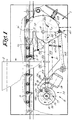
- figure 1 shows a top view of a device according to the invention, whereby a part of a conveyor element is also represented;
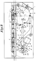
- figures 2 and 3 show the device from figure 1 in other positions, however without the conveyor element being represented;
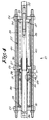
- figure 4 shows a section of the part which is indicated in figure 1 with F4 to a larger scale.
-
- As represented in figure 1, the invention concerns a
device 1 for uncoupling and/or coupling conveyor elements 2, such as a trolley, in relation to a driving mechanism, in particular adriving element 3 thereof, such as a drag chain. - As is known, the conveyor element 2 can hereby be moved by means of a
drag pin 4 or such. Thedrag pin 4 can hereby be taken along by aprotrusion 5 provided on thedriving element 3. - The above-mentioned
device 1 for coupling and/or uncoupling the conveyor elements 2 in relation to thedriving element 3 consists of arotatable element 6 in which is provided aguide 7 for adrag pin 4 of a conveyor element 2 and driving means 8 to rotate therotatable element 6, such that a conveyor element 2 can be uncoupled from and/or coupled to the drivingelement 3 by turning therotatable element 6 and by putting it in a given angular position. - The
rotatable element 6 can have various forms, but it preferably consists of a disc which can rotate around apivot 9, whereas theguide 7 provided in it consists of a recess which is confined by two guidingedges - When the disc is in a first position A, as represented in the figures 1 and 2, the guiding
edge 10 stretches such that thedrag pin 4 of an approaching conveyor element 2 is guided outside the path of thedriving element 3 according to the course X represented in figure 2. - By rotating the
rotatable element 6 into a position B, as represented in figure 3, theguiding edge 11 makes sure that thedrag pin 4 is forced back into the path of thedriving element 3 over afixed guide 12. - In the example represented, the above-mentioned driving means 8 consist of an
electric motor 13 and acrank mechanism 14 which is driven by themotor 13 and which converts the rotating movement R in a to and fro rocking motion T of therotatable element 6. Thiscrank mechanism 14 may for example consist of a crank rotating around apivot 15, in the shape of adisc 16 which is driven by themotor 13 via agear transmission 17, and a connectingrod 18 which is connected to thedisc 16 by means of apivot 19 on the one hand, and which is connected to therotatable element 6 by means of apivot 20 on the other hand. - According to the invention, means 21 are provided between the driving means 8 and the
rotatable element 6 which can give way when therotatable element 6 jams. - In the example represented, these means 21 are part of the above-mentioned connecting
rod 18. It is clear, however, that these means 21 can also be provided in another place. - As described in the introduction, these means 21 preferably consist of an elastic, deformable connection, in this case between the
pivots device 1 functions normally, there is no or almost no deformation and the distance between thepivots rotatable element 6 jams, the connection can be elastically elongated and/or compressed, such that the driving means 8 can carry out a normal working cycle. - As represented in figure 4, the above-mentioned elastic, deformable connection preferably consists of a
cylinder 22 with twoend walls wall 25; afirst coupling bar 26 which can be moved in thecylinder 22, which goes through thefirst end wall 23 and which is coupled to the driving means 8, whereby thiscoupling bar 26 is provided with astop 27 which cooperates with afirst side 28 of the dividingwall 25, whereby thisstop 27 prevents thefirst coupling bar 26 from being pushed in thecylinder 22; afirst compression spring 29 which is provided between theinside 30 of thefirst end wall 23 and astop 31 on thefirst coupling bar 26; asecond coupling bar 32 which can be moved in thecylinder 22 which goes through thesecond end wall 24 and which is connected to therotatable element 6, whereby thiscoupling bar 32 is provided with astop 33 which cooperates with theinside 34 of thesecond end wall 24, whereby thisstop 33 prevents thesecond coupling bar 32 from sliding out of thecylinder 22; and asecond compression spring 35 which is provided between thesecond side 36 of the dividingwall 25 and astop 37 on thesecond coupling bar 32. - In order to obtain a constructional simple design, the
cylinder 22 is preferably composed of twocylinder parts end wall 23 and the dividingwall 25 on the one hand, and between the dividingwall 25 and theend wall 24 on the other hand, whereby the whole is held together by means ofrods 40 which go through thewalls - The
device 1 can possibly be equipped with amechanical interlock 41 which can interlock therotatable element 6 in the above-mentioned position A in order to prevent theelement 6 from turning when adrag pin 4 slides along the guidingedge 10. - This
interlock 41 preferably consists of arotatable arm 42 with afirst pawl 43 which can mesh in arecess 44 in therotatable element 6 and asecond pawl 45 which cooperates with the perimeter of a disc driven by themotor 13, in this case the above-mentioneddisc 16, and which takes place in arecess 46 on the perimeter of thisdisc 16, whereby theinterlock 41 is switched on when thesecond pawl 45 moves in therecess 46 of thedisc 16. Thearm 42 is hereby forced into one direction by means of aspring 47. - According to the invention, the above-mentioned connection is hereby provided with a
play 48 which allows for a rotation of thedisc 16 over a small angle without therotatable element 6 being moved, whereby thisplay 48 is so large that the interlock can be uncoupled during this rotation. As represented in figure 4, thisplay 48 can be obtained by using such acompression spring 29 or by mounting thiscompression spring 29 such that it allows for a free movement of thefirst coupling bar 26 in relation to thecylinder 22 over a certain distance D. In the example represented, use is made to this end of a slidable connectingpiece 49 which retains thecompression spring 29 and which is provided with astop 50 which can cooperate with thestop 31. Thefirst coupling bar 26 can hereby move freely between a position in which thestop 27 makes contact with theside 28 and a position in which thestop 31 acts on thecompression spring 29 through the intervention of the connectingpiece 49. - It is clear that the
device 1 can be equipped with additional accessories. - Depending on the way in which the
device 1 must be controlled, use can be made for example of detectors and/or an encoder which are not represented in the drawings to determine the position of thedisc 16. - Further, use can be made of a
guide 54 which can be moved against the force of aspring 53 which makes sure that the conveyor element 2 is gradually slowed down via thedrag pin 4 when it is uncoupled from thedriving element 3. - The working of the
device 1 can be derived from the accompanying drawings and is mainly as follows. - When an approaching conveyor element 2 must be uncoupled, the
rotatable element 6 is maintained in the rest position A. Thedrag pin 4 which is taken along by the drag chain then makes contact with the guidingedge 10 and is forced in theguide 7 as represented in figure 2. As thedrag pin 4 is situated outside the path of the drag chain, in particular of theprotrusions 5, the drag movement is interrupted and the conveyor element comes to a standstill. - In order to drag the conveyor element 2, the
crank mechanism 4 is moved to and from over one cycle by making thedisc 16, via the control of themotor 13, make one rotation. - First, the
first coupling bar 26 of figure 4 is shifted to the left, over the distance D, without following thecylinder 22 and thesecond coupling bar 32. Therotatable element 6 keeps standing still during this movement. As thepawl 45 is forced out of therecess 46, the interlocking 41 comes loose. The short standstill of therotatable element 6 makes it possible to freely take thepawl 43 out of therecess 44. - As the
crank 16 is moved further, thestop 31 makes contact with thestop 50. Since thespring 29 will only be compressed under abnormally large forces, thecylinder 22 and thecoupling bar 32 are drawn along, so that therotatable element 6 is brought in the position B of figure 3 and the above-mentioneddrag pin 4 is brought back in the path of thedriving element 3, and consequently is taken along by thisdriving element 3. - As the
crank 16 is moved still further, therotatable element 6 is turned back in the position A. - When the
rotatable element 6 jams, for any reason whatsoever, for example because adrag pin 4 becomes locked in an abnormal way between theelement 6 and another part of the device, the security device is activated, which implies that themotor 13 can continue to work normally without the disadvantages occurring as mentioned in the introduction. In a concrete manner, this means that, in the example represented, thespring 29 will be compressed when theelement 6 is jammed as the connectingrod 18 moves to the left, and that thespring 35 will be compressed when theelement 6 is jammed as the connectingrod 18 moves to the right, so that in both cases thepivot 19 can move, whereas thepivot 20 stands still. - It should be noted that the position of the figures 1 and 2 preferably forms the rest position, but that this is not necessarily so. In order to obtain that the driving means 8 are always stopped in the rest position, the
motor 13 can be controlled in various manners. According to one possibility, use can be made of a servomotor which each time carries out a specific rotation. According to another possibility, an interruption contact can be provided on thearm 42. - The present invention is by no means limited to the embodiment described as an example and represented in the drawings; on the contrary, such a device for uncoupling and/or coupling a conveyor element 2 in relation to a drag mechanism can be made in various forms and dimensions while still remaining within the scope of the invention.
Claims (10)
- Device for coupling and/or uncoupling conveyor elements in relation to a driving mechanism, consisting of a rotatable element (6) in which is provided a guide (7) for a drag pin (4) of a conveyor element (2) and driving means (8) to rotate the rotatable element (6), such that a conveyor element (2), as a result of the rotation of the rotatable element (6) and by putting it in a given angular position, can be uncoupled from and/or coupled to the driving mechanism, characterized in that means (21) are provided between the driving means (8) and the rotatable element (6) which can give way when the rotatable element (6) jams.
- Device according to claim 1, characterized in that the above-mentioned means (21) consist of an elastic, deformable connection.
- Device according to claim 2, characterized in that the connection offers some initial resistance against the deformation, which is so great that a deformation only occurs when there is a jam.
- Device according to claim 2 or 3, characterized in that the above-mentioned connection consists of axially slidable parts in between which are provided springs (29-35).
- Device according to claim 4, characterized in that the above-mentioned connection is at least provided with a spring (29) which allows for an extension of the connection.
- Device according to claim 4 or 5, characterized in that the above-mentioned connection is at least provided with a spring (35) which allows for a shortening of the connection.
- Device according to claim 4, 5 or 6, characterized in that the connection mainly consists of a cylinder (22) with two end walls (23-24) and a dividing wall (25); a first coupling bar (26) which can be moved in the cylinder (22), which goes through the first end wall (23) and which is coupled to the driving means (8), whereby this coupling bar (26) is provided with a stop (27) which cooperates with a first side (28) of the dividing wall (25), whereby this stop (27) prevents the first coupling bar (26) from being pushed in the cylinder (22); a first compression spring (29) which is provided between the inside (30) of the first end wall (23) and a stop (31) on the first coupling bar (26); a second coupling bar (32) which can be moved in the cylinder (22) which goes through the second end wall (24) and which is connected to the rotatable element (6), whereby this coupling bar (32) is provided with a stop (33) which cooperates with the second end wall (24), whereby this stop (33) prevents the second coupling bar (32) from sliding out of the cylinder (22); and a second compression spring (35) which is provided between the second side (36) of the dividing wall (25) and a stop (37) on the second coupling bar (32).
- Device according to any of the preceding claims, characterized in that the driving means (8) make use of an electric motor (13).
- Device according to claim 8 and any of claims 2 to 7, characterized in that the above-mentioned connection is part of a connecting rod (18) between a crank driven by the motor (13) and the above-mentioned rotatable element (6).
- Device according to claim 9, characterized in that it is provided with a mechanical interlock (41) which can interlock the rotatable element (6) in the position (A) whereby a conveyor element (2) is brought to a standstill; in that this interlock (41) consists of a rotatable arm (42) with a first pawl (43) which can mesh in a recess (44) in the rotatable element (6) and a second pawl (45) which cooperates with the perimeter of a disc (16) driven by the motor (13), and which can take place in a recess (46) on the perimeter of this disc (16), whereby the interlock (41) is switched on when the second pawl (45) moves in the recess (46) of the disc (16); and in that the connection is provided with a play (48) which allows for a rotation of the disc (16) over a small angle without the rotatable element (6) being moved, whereby this play (48) is so large that the interlock (41) can be uncoupled during this rotation.
Applications Claiming Priority (2)
| Application Number | Priority Date | Filing Date | Title |
|---|---|---|---|
| BE9400999A BE1008851A3 (en) | 1994-11-03 | 1994-11-03 | DEVICE FOR RELEASING AND / OR LINKING ELEMENTS OF TRANSPORT TOV a drive mechanism. |
| BE9400999 | 1994-11-03 |
Publications (2)
| Publication Number | Publication Date |
|---|---|
| EP0710596A1 EP0710596A1 (en) | 1996-05-08 |
| EP0710596B1 true EP0710596B1 (en) | 1999-07-28 |
Family
ID=3888457
Family Applications (1)
| Application Number | Title | Priority Date | Filing Date |
|---|---|---|---|
| EP95202795A Expired - Lifetime EP0710596B1 (en) | 1994-11-03 | 1995-10-17 | Device for coupling and/or uncoupling conveyor elements in relation to a driving mechanism |
Country Status (9)
| Country | Link |
|---|---|
| EP (1) | EP0710596B1 (en) |
| JP (1) | JPH08208018A (en) |
| AT (1) | ATE182532T1 (en) |
| AU (1) | AU688124B2 (en) |
| BE (1) | BE1008851A3 (en) |
| CZ (1) | CZ285995A3 (en) |
| DE (1) | DE69511041T2 (en) |
| HU (1) | HUT72998A (en) |
| PL (1) | PL311220A1 (en) |
Families Citing this family (1)
| Publication number | Priority date | Publication date | Assignee | Title |
|---|---|---|---|---|
| JP5548255B2 (en) * | 2010-03-02 | 2014-07-16 | メタルエンジニアリング株式会社 | Cart carrier |
Family Cites Families (5)
| Publication number | Priority date | Publication date | Assignee | Title |
|---|---|---|---|---|
| US3648618A (en) * | 1970-03-09 | 1972-03-14 | Cutler Hammer Inc | Subfloor conveyor system and dolly therefor |
| US3796915A (en) * | 1970-10-16 | 1974-03-12 | Agfa Gevaert Ag | Illumination installation |
| US4020768A (en) * | 1975-07-21 | 1977-05-03 | Si Handling Systems, Inc. | Tow line accumulator |
| JPH05259478A (en) * | 1992-03-12 | 1993-10-08 | Fuji Electric Co Ltd | Manufacture of semiconductor pressure sensor |
| BE1005998A3 (en) * | 1992-06-18 | 1994-04-12 | Egemin Elekt Goeder Marine Ind | Method and device for releasing and / or feedback and / or linked like transport elements to drive mechanism. |
-
1994
- 1994-11-03 BE BE9400999A patent/BE1008851A3/en not_active IP Right Cessation
-
1995
- 1995-10-17 AT AT95202795T patent/ATE182532T1/en not_active IP Right Cessation
- 1995-10-17 DE DE69511041T patent/DE69511041T2/en not_active Expired - Fee Related
- 1995-10-17 EP EP95202795A patent/EP0710596B1/en not_active Expired - Lifetime
- 1995-10-24 AU AU34434/95A patent/AU688124B2/en not_active Ceased
- 1995-10-27 JP JP7280507A patent/JPH08208018A/en active Pending
- 1995-10-30 HU HU9503097A patent/HUT72998A/en unknown
- 1995-11-01 CZ CZ952859A patent/CZ285995A3/en unknown
- 1995-11-02 PL PL95311220A patent/PL311220A1/en unknown
Also Published As
| Publication number | Publication date |
|---|---|
| BE1008851A3 (en) | 1996-08-06 |
| DE69511041T2 (en) | 1999-12-30 |
| AU688124B2 (en) | 1998-03-05 |
| HU9503097D0 (en) | 1995-12-28 |
| DE69511041D1 (en) | 1999-09-02 |
| PL311220A1 (en) | 1996-05-13 |
| HUT72998A (en) | 1996-06-28 |
| JPH08208018A (en) | 1996-08-13 |
| EP0710596A1 (en) | 1996-05-08 |
| ATE182532T1 (en) | 1999-08-15 |
| AU3443495A (en) | 1996-05-09 |
| CZ285995A3 (en) | 1996-07-17 |
Similar Documents
| Publication | Publication Date | Title |
|---|---|---|
| US5169223A (en) | Telescopic cover apparatus | |
| US4267875A (en) | Sliding clutch for venetian blind | |
| CN101425401B (en) | Electromagnetic actuator equipped with a mechanical brake of the type with a wound-coil spring | |
| US5275250A (en) | Vehicle steering control device | |
| EP0710596B1 (en) | Device for coupling and/or uncoupling conveyor elements in relation to a driving mechanism | |
| CN111609130B (en) | Emergency parking device for vehicle and vehicle with same | |
| EP0624703A1 (en) | Chain operator for windows | |
| DK173190B1 (en) | Method and apparatus for pressure and / or traction transmission | |
| JP3824381B2 (en) | Safety switch | |
| US4294553A (en) | Ribbon feed mechanism | |
| US6247580B1 (en) | Actuator for a bi-directional conveyor belt | |
| JPS6325101B2 (en) | ||
| US5050644A (en) | Coupling arrangement for a loom harness shaft | |
| US5954108A (en) | Drive unit for a vertical blind | |
| US4118886A (en) | Toy elevator safety override drive mechanism | |
| WO2014003453A1 (en) | Linear motion apparatus for refrigerator | |
| KR100916081B1 (en) | Device for selecting a cleaner through a direction of reversible belt | |
| EP1413701B1 (en) | Safety device for a sectional closing element, such as a door, a main door, a gate or suchlike | |
| ITMI941060A1 (en) | DEVICE FOR AUTOMATIC OPERATION OF A STAND | |
| EP1835104B1 (en) | Safety device for a sectional frame such as a door, main door, gate or suchlike | |
| CN112109114B (en) | Door opening and closing mechanism and robot | |
| CN217502551U (en) | Manual unlocking device for gear shifter and gear shifter | |
| KR100244357B1 (en) | Cassette loading apparatus | |
| JPS5919620Y2 (en) | Gear shift instruction arm in gear shift interlocking device | |
| SU1315698A1 (en) | Turn-over device |
Legal Events
| Date | Code | Title | Description |
|---|---|---|---|
| PUAI | Public reference made under article 153(3) epc to a published international application that has entered the european phase |
Free format text: ORIGINAL CODE: 0009012 |
|
| AK | Designated contracting states |
Kind code of ref document: A1 Designated state(s): AT CH DE DK ES FR GB GR IE IT LI LU MC NL PT SE |
|
| 17P | Request for examination filed |
Effective date: 19960523 |
|
| GRAG | Despatch of communication of intention to grant |
Free format text: ORIGINAL CODE: EPIDOS AGRA |
|
| 17Q | First examination report despatched |
Effective date: 19981001 |
|
| GRAG | Despatch of communication of intention to grant |
Free format text: ORIGINAL CODE: EPIDOS AGRA |
|
| GRAH | Despatch of communication of intention to grant a patent |
Free format text: ORIGINAL CODE: EPIDOS IGRA |
|
| GRAH | Despatch of communication of intention to grant a patent |
Free format text: ORIGINAL CODE: EPIDOS IGRA |
|
| GRAA | (expected) grant |
Free format text: ORIGINAL CODE: 0009210 |
|
| AK | Designated contracting states |
Kind code of ref document: B1 Designated state(s): AT CH DE DK ES FR GB GR IE IT LI LU MC NL PT SE |
|
| PG25 | Lapsed in a contracting state [announced via postgrant information from national office to epo] |
Ref country code: SE Free format text: LAPSE BECAUSE OF FAILURE TO SUBMIT A TRANSLATION OF THE DESCRIPTION OR TO PAY THE FEE WITHIN THE PRESCRIBED TIME-LIMIT Effective date: 19990728 Ref country code: NL Free format text: LAPSE BECAUSE OF FAILURE TO SUBMIT A TRANSLATION OF THE DESCRIPTION OR TO PAY THE FEE WITHIN THE PRESCRIBED TIME-LIMIT Effective date: 19990728 Ref country code: LI Free format text: LAPSE BECAUSE OF FAILURE TO SUBMIT A TRANSLATION OF THE DESCRIPTION OR TO PAY THE FEE WITHIN THE PRESCRIBED TIME-LIMIT Effective date: 19990728 Ref country code: IT Free format text: LAPSE BECAUSE OF FAILURE TO SUBMIT A TRANSLATION OF THE DESCRIPTION OR TO PAY THE FEE WITHIN THE PRE;WARNING: LAPSES OF ITALIAN PATENTS WITH EFFECTIVE DATE BEFORE 2007 MAY HAVE OCCURRED AT ANY TIME BEFORE 2007. THE CORRECT EFFECTIVE DATE MAY BE DIFFERENT FROM THE ONE RECORDED.SCRIBED TIME-LIMIT Effective date: 19990728 Ref country code: GR Free format text: LAPSE BECAUSE OF NON-PAYMENT OF DUE FEES Effective date: 19990728 Ref country code: FR Free format text: LAPSE BECAUSE OF FAILURE TO SUBMIT A TRANSLATION OF THE DESCRIPTION OR TO PAY THE FEE WITHIN THE PRESCRIBED TIME-LIMIT Effective date: 19990728 Ref country code: ES Free format text: THE PATENT HAS BEEN ANNULLED BY A DECISION OF A NATIONAL AUTHORITY Effective date: 19990728 Ref country code: CH Free format text: LAPSE BECAUSE OF FAILURE TO SUBMIT A TRANSLATION OF THE DESCRIPTION OR TO PAY THE FEE WITHIN THE PRESCRIBED TIME-LIMIT Effective date: 19990728 Ref country code: AT Free format text: LAPSE BECAUSE OF FAILURE TO SUBMIT A TRANSLATION OF THE DESCRIPTION OR TO PAY THE FEE WITHIN THE PRESCRIBED TIME-LIMIT Effective date: 19990728 |
|
| REF | Corresponds to: |
Ref document number: 182532 Country of ref document: AT Date of ref document: 19990815 Kind code of ref document: T |
|
| REG | Reference to a national code |
Ref country code: CH Ref legal event code: EP |
|
| REF | Corresponds to: |
Ref document number: 69511041 Country of ref document: DE Date of ref document: 19990902 |
|
| PGFP | Annual fee paid to national office [announced via postgrant information from national office to epo] |
Ref country code: SE Payment date: 19991004 Year of fee payment: 5 |
|
| REG | Reference to a national code |
Ref country code: IE Ref legal event code: FG4D |
|
| PGFP | Annual fee paid to national office [announced via postgrant information from national office to epo] |
Ref country code: NL Payment date: 19991026 Year of fee payment: 5 |
|
| PG25 | Lapsed in a contracting state [announced via postgrant information from national office to epo] |
Ref country code: PT Free format text: LAPSE BECAUSE OF FAILURE TO SUBMIT A TRANSLATION OF THE DESCRIPTION OR TO PAY THE FEE WITHIN THE PRESCRIBED TIME-LIMIT Effective date: 19991028 Ref country code: DK Free format text: LAPSE BECAUSE OF FAILURE TO SUBMIT A TRANSLATION OF THE DESCRIPTION OR TO PAY THE FEE WITHIN THE PRESCRIBED TIME-LIMIT Effective date: 19991028 |
|
| EN | Fr: translation not filed | ||
| NLV1 | Nl: lapsed or annulled due to failure to fulfill the requirements of art. 29p and 29m of the patents act | ||
| REG | Reference to a national code |
Ref country code: CH Ref legal event code: PL |
|
| PLBE | No opposition filed within time limit |
Free format text: ORIGINAL CODE: 0009261 |
|
| STAA | Information on the status of an ep patent application or granted ep patent |
Free format text: STATUS: NO OPPOSITION FILED WITHIN TIME LIMIT |
|
| 26N | No opposition filed | ||
| PGFP | Annual fee paid to national office [announced via postgrant information from national office to epo] |
Ref country code: LU Payment date: 20010918 Year of fee payment: 7 |
|
| PGFP | Annual fee paid to national office [announced via postgrant information from national office to epo] |
Ref country code: IE Payment date: 20010920 Year of fee payment: 7 |
|
| PGFP | Annual fee paid to national office [announced via postgrant information from national office to epo] |
Ref country code: MC Payment date: 20010925 Year of fee payment: 7 |
|
| PGFP | Annual fee paid to national office [announced via postgrant information from national office to epo] |
Ref country code: DE Payment date: 20011008 Year of fee payment: 7 |
|
| PGFP | Annual fee paid to national office [announced via postgrant information from national office to epo] |
Ref country code: GB Payment date: 20011016 Year of fee payment: 7 |
|
| REG | Reference to a national code |
Ref country code: GB Ref legal event code: IF02 |
|
| PG25 | Lapsed in a contracting state [announced via postgrant information from national office to epo] |
Ref country code: LU Free format text: LAPSE BECAUSE OF NON-PAYMENT OF DUE FEES Effective date: 20021017 Ref country code: IE Free format text: LAPSE BECAUSE OF NON-PAYMENT OF DUE FEES Effective date: 20021017 Ref country code: GB Free format text: LAPSE BECAUSE OF NON-PAYMENT OF DUE FEES Effective date: 20021017 |
|
| PG25 | Lapsed in a contracting state [announced via postgrant information from national office to epo] |
Ref country code: MC Free format text: LAPSE BECAUSE OF NON-PAYMENT OF DUE FEES Effective date: 20030501 Ref country code: DE Free format text: LAPSE BECAUSE OF NON-PAYMENT OF DUE FEES Effective date: 20030501 |
|
| GBPC | Gb: european patent ceased through non-payment of renewal fee |
Effective date: 20021017 |
|
| REG | Reference to a national code |
Ref country code: IE Ref legal event code: MM4A |