EP0709918B1 - Bloc de connexion multipolaire à double rangée - Google Patents
Bloc de connexion multipolaire à double rangée Download PDFInfo
- Publication number
- EP0709918B1 EP0709918B1 EP95113808A EP95113808A EP0709918B1 EP 0709918 B1 EP0709918 B1 EP 0709918B1 EP 95113808 A EP95113808 A EP 95113808A EP 95113808 A EP95113808 A EP 95113808A EP 0709918 B1 EP0709918 B1 EP 0709918B1
- Authority
- EP
- European Patent Office
- Prior art keywords
- connecting pin
- casing
- level
- receiving means
- pin strip
- Prior art date
- Legal status (The legal status is an assumption and is not a legal conclusion. Google has not performed a legal analysis and makes no representation as to the accuracy of the status listed.)
- Expired - Lifetime
Links
- 230000005405 multipole Effects 0.000 claims abstract description 9
- 229920003023 plastic Polymers 0.000 claims description 3
- 239000004033 plastic Substances 0.000 claims description 3
- 239000000463 material Substances 0.000 claims 1
- 239000011810 insulating material Substances 0.000 abstract 1
- 238000004519 manufacturing process Methods 0.000 description 5
- 239000011324 bead Substances 0.000 description 4
- 238000012986 modification Methods 0.000 description 2
- 230000004048 modification Effects 0.000 description 2
- 230000006978 adaptation Effects 0.000 description 1
- 230000000712 assembly Effects 0.000 description 1
- 238000000429 assembly Methods 0.000 description 1
- 239000003086 colorant Substances 0.000 description 1
- 239000002360 explosive Substances 0.000 description 1
- 238000003780 insertion Methods 0.000 description 1
- 230000037431 insertion Effects 0.000 description 1
- 230000013011 mating Effects 0.000 description 1
- 230000003287 optical effect Effects 0.000 description 1
- 125000006850 spacer group Chemical group 0.000 description 1
Images


Classifications
-
- H—ELECTRICITY
- H01—ELECTRIC ELEMENTS
- H01R—ELECTRICALLY-CONDUCTIVE CONNECTIONS; STRUCTURAL ASSOCIATIONS OF A PLURALITY OF MUTUALLY-INSULATED ELECTRICAL CONNECTING ELEMENTS; COUPLING DEVICES; CURRENT COLLECTORS
- H01R12/00—Structural associations of a plurality of mutually-insulated electrical connecting elements, specially adapted for printed circuits, e.g. printed circuit boards [PCB], flat or ribbon cables, or like generally planar structures, e.g. terminal strips, terminal blocks; Coupling devices specially adapted for printed circuits, flat or ribbon cables, or like generally planar structures; Terminals specially adapted for contact with, or insertion into, printed circuits, flat or ribbon cables, or like generally planar structures
- H01R12/70—Coupling devices
- H01R12/71—Coupling devices for rigid printing circuits or like structures
- H01R12/72—Coupling devices for rigid printing circuits or like structures coupling with the edge of the rigid printed circuits or like structures
- H01R12/722—Coupling devices for rigid printing circuits or like structures coupling with the edge of the rigid printed circuits or like structures coupling devices mounted on the edge of the printed circuits
- H01R12/724—Coupling devices for rigid printing circuits or like structures coupling with the edge of the rigid printed circuits or like structures coupling devices mounted on the edge of the printed circuits containing contact members forming a right angle
Definitions
- the invention relates to a double-decker, multi-pin connector strip with electrical Connections that are on top of each other on the two floors and with one Housing made of electrically insulating plastic.
- double-decker Pin headers which are arranged in particular on printed circuit boards special double-storey housings with staggered levels provided, in which the individual electrical connections and their pins to be ordered.
- the housings are more like that double-level connector strips in their manufacture complicated because in both Floors with complex mating face cores must be worked. For the production the housing therefore requires very expensive special tools.
- Known two-tier connector strips is, for example, to EP 0 584 481 A2.
- the present invention is therefore based on the object to create two-story, multi-pin connector header that is easy to manufacture and is particularly flexible and easy to use.
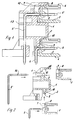
- the solution according to the invention essentially consists in a carrier housing one plug-in receptacle on each floor, in the respective one-level connector strips are used with their housings, with 2 before inserting the pin header 4 into the socket 2 and in the upper Plug receptacle 3 after inserting the pin header 4 into the plug receptacle 3 angled pins 6 and 6 'in the housing 5 of the respective pin header 4 can be used.
- Such a carrier housing is due to the omission of plug-in face cores inexpensive tool in a short manufacturing process easy and inexpensive to manufacture.
- Commercially available single-level connector strips can be used with their housings used in such a simple manner in such a carrier housing will. The arrangement becomes particularly simple when commercial, single-level connector strips are used, in which in their housing as electrically conductive connection as a whole, i.e. both for connection to the printed circuit board how to insert a connector, a one-piece unitary Connector pin is used.
- This one-piece, uniform connector pin which is used for Contacting between the one-story pin header, for example Printed circuit board is used, on which the two-story multi-pin connector strip is arranged is here before or after inserting the respective pin header in the associated connector in the housing of the one-piece pin header be applicable.
- This makes it possible, even in the partially assembled state double-storey multi-pin connector header to mount connector pins in particular, the assembly of pre-assembled units facilitated becomes.
- a pin header with pre-assembled can also be used Pins in the lower socket in the two-level pin header are used, whereas the second pin header is only plugged in is provided in the upper connector with the connecting pins.
- the handling convenience for the user results from the fact that it is uniform Two-tier, multi-pin connector strips to be handled stand.
- the plug-in receptacle is.
- the commercially available pin headers are provided with connector elements, for the corresponding counterparts in the plug-in receptacle of the carrier housing available.
- a particular advantage of this configuration is that the Connector pins can be designed as standard connector pins, because by the lack of a lower plate the connector pin stands up directly on a mounting location. This enables the use of purchased parts directly.
- the plug-in receptacle is Carrier housing on the upper floor a shaft open to the front, in which the Housing of a one-story pin header is inserted from the front. Angled pins can also be inserted into the housing from the rear the single-level connector pin strip and in corresponding receptacles of the carrier housing be used.
- the double-decker, multi-pin connector strip according to the invention includes a carrier housing 1 made of electrically insulating plastic, which is two-story, so has two floors, with each other There is a socket 2 or 3 on each floor.
- These plug-in receptacles 2 and 3 are configured so that they are commercially available single-level connector strips 4 used with their housings 5 can be.
- the shapes of the housing 5 more commercially available Terminal strips 4 can be the plug receptacles 2 and 3 easily, especially from the tool side without the use of plug face cores, getting produced.
- the plug receptacle is 2 of the lower floor of the carrier housing 1 down and to The front of the double-level pin header is open.
- a first commercial, single-level connector 4 with your Housing 5 are used.
- a pin header 4 with angled pins 6 use.
- the angled connection pins thus represent the conductive one Connection and the connection possibility, for example, to a Printed circuit board, and on the other hand, the connection option for one to be connected, to be inserted in this connector pin 4 Connector with the corresponding number of poles or a connector system with a corresponding total number of poles.
- the commercially available pin headers 4 have connector elements on the back 7, in their juxtaposition between them Define T-slots 8.
- T-slots 8 In the illustrated embodiment, in the receptacle 2 on the lower floor of the carrier housing 1 to these T-slots 8 matching T-pieces 9 formed in their longitudinal extent are oriented downwards so that when the connector pin is inserted 4 from below into the plug-in receptacle 2 of the carrier housing 1 T-pieces 9 can enter the T-slots 8 and thus to the front and thus plug connection direction with respect to the angled connection pins 6 there is a stable, positive locking.
- the clamping is stable and stable of the housing 5 of the pin header 4 in the direction of insertion, that is downwards, on both sides in the end areas on each some T-pieces
- 9 clamping beads 10 are provided, which are on the opposite Clamp the housing area of the housing 5 in the area of the T-slots 8.
- the number of clamping beads 10 can be expected with the size of the Load, especially vibration load vary. If necessary, 9 clamping beads 10 can be provided on all T-pieces will.
- the plug-in receptacle 3 of the carrier housing 1 on the upper floor a shaft open to the front.
- the housing 5 is initially one commercially available terminal block 4, from the front, used.
- the ones that form the T-slots 8 Connector elements 7 on the rear of the housing 5 of the pin header 4 the form-fitting fixing in the shaft-shaped Plug receptacle 3 of the Surgetudes 1.
- the upper shaft wall 11 of the carrier housing 1 in one of the Number of T-slots 8 corresponding number of small, slightly protruding Locking pieces 12 provided.
- the upper shaft wall 11 is included a little bit deformable overall due to their design.
- the double-level pin header is then fully assembled, that after inserting the housing 5 into the upper receptacle 3 of the Carrier housing 1 now with regard to the assembly of the upper floor correspondingly long, angled pins 6 'by appropriate Recesses in the carrier housing 1 into the housing 5 of the pin header 4 are inserted to complete them.
- Corresponding receptacles 13 are provided in the carrier housing 1.
- the connector pins 6 ' have the usual clamping bead 14 with which they are in a corresponding receiving area of the pin header housing 5 firmly clamped can be.
- a two-story, multi-pole Terminal strip provided, in which the two in the two floors commercially available, single-level connector strips 4 with their housings 5 lie essentially one above the other in one plane.
- the carrier housing 1 with regard to the plug-in receptacles 2 and 3 so that in the two floors the pins 6, 6 'of the pin strips are staggered to each other, as is also the case with double-decker multipole pin headers is known.
Landscapes
- Connector Housings Or Holding Contact Members (AREA)
- Coupling Device And Connection With Printed Circuit (AREA)
Claims (8)
- Barrette de broches de branchement multipolaire, à deux étages, avec des branchements électriques qui se situent dans les deux étages et avec un boítier en matière plastique électriquement isolante, caractérisée par un boítier de support (1) avec des logements d'enfichage (2 ou 3) respectivement dans chaque étage, dans chacun desquels sont insérées des barrettes de broches de branchement (4) à un étage avec leurs boítiers (5), dans le logement d'enfichage (2) inférieur pouvant être insérée d'abord une barrette de broches de branchement (4) à un étage avec broches de branchement (6) coudées et dans le logement d'enfichage (3) supérieur pouvant être insérées, après insertion du boítier (5) de la barrette de broches de branchement (4) dans le logement d'enfichage (3), des broches de branchement coudées (6') dans le boítier (5) de la barrette de broches de branchement (4).
- Barrette de broches de branchement à deux étages selon la revendication 1, caractérisée en ce que le logement d'enfichage (2) du boítier de support (1) est ouvert vers le bas et vers le côté frontal dans l'étage inférieur.
- Barrette de broches de branchement à deux étages selon l'une des revendications précédentes, caractérisée en ce que le logement d'enfichage (3) du boítier de support (1) dans l'étage supérieur est un compartiment ouvert vers le côté frontal, dans lequel est inséré, à partir du côté frontal, le boítier (5) d'une barrette de broches de branchement (4) à un étage, des broches de branchements (6') coudées étant insérées à partir de la face arrière dans le boítier (5) de la barrette de broches de branchement (4) à un étage et dans des logements (13) du boítier de support (1).
- Barrette de broches de branchement à deux étages selon l'une des revendications précédentes, caractérisée en ce que dans les logements d'enfichage (2 et 3) du boítier de support (1) sont prévus des éléments de connexion par enfichage et des éléments d'assemblage par concordance de forme (9, 12) pour la fixation du boítier (5) des barrettes de broches de branchement (4).
- Barrette de broches de branchement à deux étages selon la revendication 4, caractérisée en ce que dans le logement d'enfichage (2) inférieur du boítier de support (1) sont prévues des pièces en T (9), s'étendant vers le bas, qui sont en prise avec des rainures en T (8) formées sur la face arrière du boítier (5) de la barrette de broches de branchement (4), par une succession d'éléments de connecteurs par enfichage (7).
- Barrette de broches de branchement à deux étages selon la revendication 5, caractérisée en ce qu'au moins sur quelques pièces en T (9) des bourrelets de serrage (10) sont prévus dans le logement d'enfichage (2) du boítier de support (1).
- Barrette de broches de branchement à deux étages selon la revendication 4, caractérisée en ce que sur la face intérieure de la paroi de compartiment (11) supérieure du logement d'enfichage (3) supérieur du boítier de support (1), sont prévues des pièces d'encliquetage (12), qui lorsque le boítier (5) de la barrette de broches de branchement (4) est enfiché, sont encliquetées dans des rainures en T (8) qui sont formées sur le boítier (5) par une succession d'éléments de connecteurs par enfichage (7).
- Barrette de broches de branchement à deux étages selon l'une des revendications précédentes, caractérisée en ce que les logements d'enfichage supérieur et inférieur (2 et 3) du boítier de support (1) sont maintenus ouverts sur les faces terminales du boítier support.
Applications Claiming Priority (2)
| Application Number | Priority Date | Filing Date | Title |
|---|---|---|---|
| DE9417390U DE9417390U1 (de) | 1994-10-20 | 1994-10-20 | Doppelstöckige, mehrpolige Anschlußstiftleiste |
| DE9417390U | 1994-10-29 |
Publications (2)
| Publication Number | Publication Date |
|---|---|
| EP0709918A1 EP0709918A1 (fr) | 1996-05-01 |
| EP0709918B1 true EP0709918B1 (fr) | 1998-10-14 |
Family
ID=6915472
Family Applications (1)
| Application Number | Title | Priority Date | Filing Date |
|---|---|---|---|
| EP95113808A Expired - Lifetime EP0709918B1 (fr) | 1994-10-20 | 1995-09-02 | Bloc de connexion multipolaire à double rangée |
Country Status (4)
| Country | Link |
|---|---|
| EP (1) | EP0709918B1 (fr) |
| AT (1) | ATE172328T1 (fr) |
| DE (2) | DE9417390U1 (fr) |
| ES (1) | ES2123194T3 (fr) |
Cited By (1)
| Publication number | Priority date | Publication date | Assignee | Title |
|---|---|---|---|---|
| US9078695B2 (en) | 2009-06-05 | 2015-07-14 | Ethicon Endo-Surgery, Inc. | Methods and devices for accessing a body cavity using a surgical access device with modular seal components |
Families Citing this family (3)
| Publication number | Priority date | Publication date | Assignee | Title |
|---|---|---|---|---|
| US6095826A (en) * | 1997-02-21 | 2000-08-01 | Berg Technology, Inc. | Press fit circuit board connector |
| JPH118027A (ja) * | 1997-06-13 | 1999-01-12 | Sumitomo Wiring Syst Ltd | 基板用コネクタ |
| DE102012016305A1 (de) | 2012-08-16 | 2014-05-15 | GSN Corporation GmbH & Co. KG | Steckanschluss zur Erzielung einer elektrischen Steckverbindung und Verfahren zur Herstellung eines solchen Steckanschlusses |
Family Cites Families (2)
| Publication number | Priority date | Publication date | Assignee | Title |
|---|---|---|---|---|
| DE8009238U1 (de) * | 1980-04-02 | 1980-08-14 | Weco Wester, Ebbinghaus & Co, 6450 Hanau | Zweietagenklemmenbaustein |
| DE9211314U1 (de) * | 1992-08-22 | 1992-10-29 | RIA electronic Albert Metz, 7712 Blumberg | Mehrpolige Anschlußklemme |
-
1994
- 1994-10-20 DE DE9417390U patent/DE9417390U1/de not_active Expired - Lifetime
-
1995
- 1995-09-02 EP EP95113808A patent/EP0709918B1/fr not_active Expired - Lifetime
- 1995-09-02 AT AT95113808T patent/ATE172328T1/de not_active IP Right Cessation
- 1995-09-02 ES ES95113808T patent/ES2123194T3/es not_active Expired - Lifetime
- 1995-09-02 DE DE59503919T patent/DE59503919D1/de not_active Expired - Lifetime
Cited By (1)
| Publication number | Priority date | Publication date | Assignee | Title |
|---|---|---|---|---|
| US9078695B2 (en) | 2009-06-05 | 2015-07-14 | Ethicon Endo-Surgery, Inc. | Methods and devices for accessing a body cavity using a surgical access device with modular seal components |
Also Published As
| Publication number | Publication date |
|---|---|
| ES2123194T3 (es) | 1999-01-01 |
| DE9417390U1 (de) | 1994-12-15 |
| DE59503919D1 (de) | 1998-11-19 |
| ATE172328T1 (de) | 1998-10-15 |
| EP0709918A1 (fr) | 1996-05-01 |
Similar Documents
| Publication | Publication Date | Title |
|---|---|---|
| DE3587796T2 (de) | Modularer Block und elektrische Aufbausysteme, die diesen verwenden. | |
| DE3709903C3 (de) | Elektrischer verbinder | |
| DE69204754T2 (de) | Klemmleiste für gedruckte Leiterplatten. | |
| DE3783692T2 (de) | Modulartiger elektrischer verbinder. | |
| DE69502190T2 (de) | Datenübertragungsverbinder | |
| DE102017119287B4 (de) | Modularer Steckverbinder für Leiterplatten | |
| EP3033808A1 (fr) | Cadre de retenue pour connecteur | |
| DE3903839A1 (de) | Beweglicher verbindungsstecker | |
| DE102006003752A1 (de) | Kupplung | |
| DE29508095U1 (de) | Modulares Steckverbindersystem | |
| EP0397057A1 (fr) | Assemblage pour la connexion mécanique et électrique d'une plaque de câblage d'extension à une plaque de câblage de base | |
| DE2001690B2 (de) | Relaissteckdose | |
| DE3026247C2 (de) | Hintereinander anreihbares, eine Mehrzahl von elektronischen Bauelementen aufnehmendes Gehäuse aus Isolierstoff für die Montage auf einer gemeinsamen Unterlage oder Tragschiene | |
| DE4001104A1 (de) | Steckverbindung | |
| DE2338778B2 (de) | Buchsenleiste | |
| DE102021116837A1 (de) | Anschlussleiste und Verfahren zur Herstellung der Anschlussleiste | |
| DE2615353C3 (de) | Elektrische Steckvorrichtung | |
| DE19724581A1 (de) | Steckhülse für Leiterplatten | |
| EP0709918B1 (fr) | Bloc de connexion multipolaire à double rangée | |
| DE69603884T2 (de) | Einrichtung zum Montieren einer Lampe | |
| WO2000013264A1 (fr) | Barres de bus juxtaposables | |
| DE2802643C2 (fr) | ||
| EP1445840B1 (fr) | Connecteur Electrique | |
| DE2513640B2 (de) | Mehrpolige codierte Steckverbindung | |
| DE102004019032B4 (de) | Elektrischer Leiterplatten-Steckverbinder |
Legal Events
| Date | Code | Title | Description |
|---|---|---|---|
| PUAI | Public reference made under article 153(3) epc to a published international application that has entered the european phase |
Free format text: ORIGINAL CODE: 0009012 |
|
| AK | Designated contracting states |
Kind code of ref document: A1 Designated state(s): AT CH DE ES FR GB IT LI |
|
| 17P | Request for examination filed |
Effective date: 19960529 |
|
| 17Q | First examination report despatched |
Effective date: 19970421 |
|
| GRAG | Despatch of communication of intention to grant |
Free format text: ORIGINAL CODE: EPIDOS AGRA |
|
| GRAG | Despatch of communication of intention to grant |
Free format text: ORIGINAL CODE: EPIDOS AGRA |
|
| GRAH | Despatch of communication of intention to grant a patent |
Free format text: ORIGINAL CODE: EPIDOS IGRA |
|
| ITF | It: translation for a ep patent filed | ||
| GRAH | Despatch of communication of intention to grant a patent |
Free format text: ORIGINAL CODE: EPIDOS IGRA |
|
| GRAA | (expected) grant |
Free format text: ORIGINAL CODE: 0009210 |
|
| AK | Designated contracting states |
Kind code of ref document: B1 Designated state(s): AT CH DE ES FR GB IT LI |
|
| REF | Corresponds to: |
Ref document number: 172328 Country of ref document: AT Date of ref document: 19981015 Kind code of ref document: T |
|
| REG | Reference to a national code |
Ref country code: CH Ref legal event code: NV Representative=s name: ISLER & PEDRAZZINI AG Ref country code: CH Ref legal event code: EP |
|
| REF | Corresponds to: |
Ref document number: 59503919 Country of ref document: DE Date of ref document: 19981119 |
|
| REG | Reference to a national code |
Ref country code: ES Ref legal event code: FG2A Ref document number: 2123194 Country of ref document: ES Kind code of ref document: T3 |
|
| GBT | Gb: translation of ep patent filed (gb section 77(6)(a)/1977) |
Effective date: 19981229 |
|
| ET | Fr: translation filed | ||
| PLBE | No opposition filed within time limit |
Free format text: ORIGINAL CODE: 0009261 |
|
| STAA | Information on the status of an ep patent application or granted ep patent |
Free format text: STATUS: NO OPPOSITION FILED WITHIN TIME LIMIT |
|
| 26N | No opposition filed | ||
| REG | Reference to a national code |
Ref country code: GB Ref legal event code: IF02 |
|
| REG | Reference to a national code |
Ref country code: CH Ref legal event code: PCAR Free format text: ISLER & PEDRAZZINI AG;POSTFACH 1772;8027 ZUERICH (CH) |
|
| PGFP | Annual fee paid to national office [announced via postgrant information from national office to epo] |
Ref country code: ES Payment date: 20090922 Year of fee payment: 15 |
|
| PGFP | Annual fee paid to national office [announced via postgrant information from national office to epo] |
Ref country code: GB Payment date: 20090922 Year of fee payment: 15 Ref country code: CH Payment date: 20090923 Year of fee payment: 15 Ref country code: AT Payment date: 20090916 Year of fee payment: 15 |
|
| PGFP | Annual fee paid to national office [announced via postgrant information from national office to epo] |
Ref country code: IT Payment date: 20100922 Year of fee payment: 16 |
|
| REG | Reference to a national code |
Ref country code: CH Ref legal event code: PL |
|
| GBPC | Gb: european patent ceased through non-payment of renewal fee |
Effective date: 20100902 |
|
| PG25 | Lapsed in a contracting state [announced via postgrant information from national office to epo] |
Ref country code: LI Free format text: LAPSE BECAUSE OF NON-PAYMENT OF DUE FEES Effective date: 20100930 Ref country code: CH Free format text: LAPSE BECAUSE OF NON-PAYMENT OF DUE FEES Effective date: 20100930 |
|
| PG25 | Lapsed in a contracting state [announced via postgrant information from national office to epo] |
Ref country code: GB Free format text: LAPSE BECAUSE OF NON-PAYMENT OF DUE FEES Effective date: 20100902 Ref country code: AT Free format text: LAPSE BECAUSE OF NON-PAYMENT OF DUE FEES Effective date: 20100902 |
|
| REG | Reference to a national code |
Ref country code: ES Ref legal event code: FD2A Effective date: 20111019 |
|
| PG25 | Lapsed in a contracting state [announced via postgrant information from national office to epo] |
Ref country code: ES Free format text: LAPSE BECAUSE OF NON-PAYMENT OF DUE FEES Effective date: 20100903 |
|
| PGFP | Annual fee paid to national office [announced via postgrant information from national office to epo] |
Ref country code: DE Payment date: 20110923 Year of fee payment: 17 Ref country code: FR Payment date: 20110928 Year of fee payment: 17 |
|
| REG | Reference to a national code |
Ref country code: FR Ref legal event code: ST Effective date: 20130531 |
|
| PG25 | Lapsed in a contracting state [announced via postgrant information from national office to epo] |
Ref country code: DE Free format text: LAPSE BECAUSE OF NON-PAYMENT OF DUE FEES Effective date: 20130403 |
|
| PG25 | Lapsed in a contracting state [announced via postgrant information from national office to epo] |
Ref country code: FR Free format text: LAPSE BECAUSE OF NON-PAYMENT OF DUE FEES Effective date: 20121001 Ref country code: IT Free format text: LAPSE BECAUSE OF NON-PAYMENT OF DUE FEES Effective date: 20120902 |
|
| REG | Reference to a national code |
Ref country code: DE Ref legal event code: R119 Ref document number: 59503919 Country of ref document: DE Effective date: 20130403 |