EP0709918B1 - Double row multipolar terminal block - Google Patents
Double row multipolar terminal block Download PDFInfo
- Publication number
- EP0709918B1 EP0709918B1 EP95113808A EP95113808A EP0709918B1 EP 0709918 B1 EP0709918 B1 EP 0709918B1 EP 95113808 A EP95113808 A EP 95113808A EP 95113808 A EP95113808 A EP 95113808A EP 0709918 B1 EP0709918 B1 EP 0709918B1
- Authority
- EP
- European Patent Office
- Prior art keywords
- connecting pin
- casing
- level
- receiving means
- pin strip
- Prior art date
- Legal status (The legal status is an assumption and is not a legal conclusion. Google has not performed a legal analysis and makes no representation as to the accuracy of the status listed.)
- Expired - Lifetime
Links
- 230000005405 multipole Effects 0.000 claims abstract description 9
- 229920003023 plastic Polymers 0.000 claims description 3
- 239000004033 plastic Substances 0.000 claims description 3
- 239000000463 material Substances 0.000 claims 1
- 239000011810 insulating material Substances 0.000 abstract 1
- 238000004519 manufacturing process Methods 0.000 description 5
- 239000011324 bead Substances 0.000 description 4
- 238000012986 modification Methods 0.000 description 2
- 230000004048 modification Effects 0.000 description 2
- 230000006978 adaptation Effects 0.000 description 1
- 230000000712 assembly Effects 0.000 description 1
- 238000000429 assembly Methods 0.000 description 1
- 239000003086 colorant Substances 0.000 description 1
- 239000002360 explosive Substances 0.000 description 1
- 238000003780 insertion Methods 0.000 description 1
- 230000037431 insertion Effects 0.000 description 1
- 230000013011 mating Effects 0.000 description 1
- 230000003287 optical effect Effects 0.000 description 1
- 125000006850 spacer group Chemical group 0.000 description 1
Images


Classifications
-
- H—ELECTRICITY
- H01—ELECTRIC ELEMENTS
- H01R—ELECTRICALLY-CONDUCTIVE CONNECTIONS; STRUCTURAL ASSOCIATIONS OF A PLURALITY OF MUTUALLY-INSULATED ELECTRICAL CONNECTING ELEMENTS; COUPLING DEVICES; CURRENT COLLECTORS
- H01R12/00—Structural associations of a plurality of mutually-insulated electrical connecting elements, specially adapted for printed circuits, e.g. printed circuit boards [PCB], flat or ribbon cables, or like generally planar structures, e.g. terminal strips, terminal blocks; Coupling devices specially adapted for printed circuits, flat or ribbon cables, or like generally planar structures; Terminals specially adapted for contact with, or insertion into, printed circuits, flat or ribbon cables, or like generally planar structures
- H01R12/70—Coupling devices
- H01R12/71—Coupling devices for rigid printing circuits or like structures
- H01R12/72—Coupling devices for rigid printing circuits or like structures coupling with the edge of the rigid printed circuits or like structures
- H01R12/722—Coupling devices for rigid printing circuits or like structures coupling with the edge of the rigid printed circuits or like structures coupling devices mounted on the edge of the printed circuits
- H01R12/724—Coupling devices for rigid printing circuits or like structures coupling with the edge of the rigid printed circuits or like structures coupling devices mounted on the edge of the printed circuits containing contact members forming a right angle
Definitions
- the invention relates to a double-decker, multi-pin connector strip with electrical Connections that are on top of each other on the two floors and with one Housing made of electrically insulating plastic.
- double-decker Pin headers which are arranged in particular on printed circuit boards special double-storey housings with staggered levels provided, in which the individual electrical connections and their pins to be ordered.
- the housings are more like that double-level connector strips in their manufacture complicated because in both Floors with complex mating face cores must be worked. For the production the housing therefore requires very expensive special tools.
- Known two-tier connector strips is, for example, to EP 0 584 481 A2.
- the present invention is therefore based on the object to create two-story, multi-pin connector header that is easy to manufacture and is particularly flexible and easy to use.
- the solution according to the invention essentially consists in a carrier housing one plug-in receptacle on each floor, in the respective one-level connector strips are used with their housings, with 2 before inserting the pin header 4 into the socket 2 and in the upper Plug receptacle 3 after inserting the pin header 4 into the plug receptacle 3 angled pins 6 and 6 'in the housing 5 of the respective pin header 4 can be used.
- Such a carrier housing is due to the omission of plug-in face cores inexpensive tool in a short manufacturing process easy and inexpensive to manufacture.
- Commercially available single-level connector strips can be used with their housings used in such a simple manner in such a carrier housing will. The arrangement becomes particularly simple when commercial, single-level connector strips are used, in which in their housing as electrically conductive connection as a whole, i.e. both for connection to the printed circuit board how to insert a connector, a one-piece unitary Connector pin is used.
- This one-piece, uniform connector pin which is used for Contacting between the one-story pin header, for example Printed circuit board is used, on which the two-story multi-pin connector strip is arranged is here before or after inserting the respective pin header in the associated connector in the housing of the one-piece pin header be applicable.
- This makes it possible, even in the partially assembled state double-storey multi-pin connector header to mount connector pins in particular, the assembly of pre-assembled units facilitated becomes.
- a pin header with pre-assembled can also be used Pins in the lower socket in the two-level pin header are used, whereas the second pin header is only plugged in is provided in the upper connector with the connecting pins.
- the handling convenience for the user results from the fact that it is uniform Two-tier, multi-pin connector strips to be handled stand.
- the plug-in receptacle is.
- the commercially available pin headers are provided with connector elements, for the corresponding counterparts in the plug-in receptacle of the carrier housing available.
- a particular advantage of this configuration is that the Connector pins can be designed as standard connector pins, because by the lack of a lower plate the connector pin stands up directly on a mounting location. This enables the use of purchased parts directly.
- the plug-in receptacle is Carrier housing on the upper floor a shaft open to the front, in which the Housing of a one-story pin header is inserted from the front. Angled pins can also be inserted into the housing from the rear the single-level connector pin strip and in corresponding receptacles of the carrier housing be used.
- the double-decker, multi-pin connector strip according to the invention includes a carrier housing 1 made of electrically insulating plastic, which is two-story, so has two floors, with each other There is a socket 2 or 3 on each floor.
- These plug-in receptacles 2 and 3 are configured so that they are commercially available single-level connector strips 4 used with their housings 5 can be.
- the shapes of the housing 5 more commercially available Terminal strips 4 can be the plug receptacles 2 and 3 easily, especially from the tool side without the use of plug face cores, getting produced.
- the plug receptacle is 2 of the lower floor of the carrier housing 1 down and to The front of the double-level pin header is open.
- a first commercial, single-level connector 4 with your Housing 5 are used.
- a pin header 4 with angled pins 6 use.
- the angled connection pins thus represent the conductive one Connection and the connection possibility, for example, to a Printed circuit board, and on the other hand, the connection option for one to be connected, to be inserted in this connector pin 4 Connector with the corresponding number of poles or a connector system with a corresponding total number of poles.
- the commercially available pin headers 4 have connector elements on the back 7, in their juxtaposition between them Define T-slots 8.
- T-slots 8 In the illustrated embodiment, in the receptacle 2 on the lower floor of the carrier housing 1 to these T-slots 8 matching T-pieces 9 formed in their longitudinal extent are oriented downwards so that when the connector pin is inserted 4 from below into the plug-in receptacle 2 of the carrier housing 1 T-pieces 9 can enter the T-slots 8 and thus to the front and thus plug connection direction with respect to the angled connection pins 6 there is a stable, positive locking.
- the clamping is stable and stable of the housing 5 of the pin header 4 in the direction of insertion, that is downwards, on both sides in the end areas on each some T-pieces
- 9 clamping beads 10 are provided, which are on the opposite Clamp the housing area of the housing 5 in the area of the T-slots 8.
- the number of clamping beads 10 can be expected with the size of the Load, especially vibration load vary. If necessary, 9 clamping beads 10 can be provided on all T-pieces will.
- the plug-in receptacle 3 of the carrier housing 1 on the upper floor a shaft open to the front.
- the housing 5 is initially one commercially available terminal block 4, from the front, used.
- the ones that form the T-slots 8 Connector elements 7 on the rear of the housing 5 of the pin header 4 the form-fitting fixing in the shaft-shaped Plug receptacle 3 of the Surgetudes 1.
- the upper shaft wall 11 of the carrier housing 1 in one of the Number of T-slots 8 corresponding number of small, slightly protruding Locking pieces 12 provided.
- the upper shaft wall 11 is included a little bit deformable overall due to their design.
- the double-level pin header is then fully assembled, that after inserting the housing 5 into the upper receptacle 3 of the Carrier housing 1 now with regard to the assembly of the upper floor correspondingly long, angled pins 6 'by appropriate Recesses in the carrier housing 1 into the housing 5 of the pin header 4 are inserted to complete them.
- Corresponding receptacles 13 are provided in the carrier housing 1.
- the connector pins 6 ' have the usual clamping bead 14 with which they are in a corresponding receiving area of the pin header housing 5 firmly clamped can be.
- a two-story, multi-pole Terminal strip provided, in which the two in the two floors commercially available, single-level connector strips 4 with their housings 5 lie essentially one above the other in one plane.
- the carrier housing 1 with regard to the plug-in receptacles 2 and 3 so that in the two floors the pins 6, 6 'of the pin strips are staggered to each other, as is also the case with double-decker multipole pin headers is known.
Landscapes
- Connector Housings Or Holding Contact Members (AREA)
- Coupling Device And Connection With Printed Circuit (AREA)
Abstract
Description
Die Erfindung betrifft eine doppelstöckige, mehrpolige Anschlußstiftleiste mit elektrischen Anschlüssen, die in den beiden Etagen übereinanderliegen, und mit einem Gehäuse aus elektrisch isolierendem Kunststoff. Bei den bekannten doppelstöckigen Anschlußstiftleisten, die insbesondere auf Leiterplatten angeordnet werden, sind spezielle doppelstöckige, etagenweise versetzte Aufnahmeräume habende Gehäuse vorgesehen, in denen dann die einzelnen elektrischen Anschlüsse und deren Stifte angeordnet werden. Abgesehen von Montageproblemen sind die Gehäuse derartiger doppelstöckiger Anschlußstiftleisten in ihrer Herstellung kompliziert, da in beiden Etagen mit komplexen Steckgesichtkernen gearbeitet werden muß. Zur Herstellung der Gehäuse werden somit sehr teure Spezialwerkzeuge benötigt. Bezüglich derartiger vorbekannter doppelstöckiger Anschlußstiftleisten ist beispielsweise auf die EP 0 584 481 A2 zu verweisen.The invention relates to a double-decker, multi-pin connector strip with electrical Connections that are on top of each other on the two floors and with one Housing made of electrically insulating plastic. In the well-known double-decker Pin headers, which are arranged in particular on printed circuit boards special double-storey housings with staggered levels provided, in which the individual electrical connections and their pins to be ordered. Apart from assembly problems, the housings are more like that double-level connector strips in their manufacture complicated because in both Floors with complex mating face cores must be worked. For the production the housing therefore requires very expensive special tools. Regarding such Known two-tier connector strips is, for example, to EP 0 584 481 A2.
Es ist andererseits bekannt, eine doppelstöckige etagenmäßig versetzte Anordnung von Anschlußklemmen dadurch zu erreichen, daß man beispielsweise eine normale, einstöckige, mehrpolige Anschlußklemme direkt auf einer Leiterplatte anordnet und dann eine zweite, einstöckige, mehrpolige Anschlußklemme in gewünschtem Höhenversatz dazu mit Hilfe von Distanzblöcken anbringt. Diese Ausgestaltung ist handhabungsunbequem, insbesondere für den Anwender, der sich die gewünschte doppelstöckige Anordnung vor Ort zusammenmontieren muß.On the other hand, it is known to be a two-story staggered arrangement of connecting terminals in that, for example, a normal, arranges single-storey, multi-pole terminal directly on a circuit board and then a second, one-storey, multi-pole terminal in the desired height offset attach using spacer blocks. This configuration is inconvenient to use, especially for the user who wants the desired two-story Assembly must be assembled on site.
Es ist weiterhin aus dem DE-GM 80 09 238 ein Zweietagenklemmbaustein bekannt, bei dem eine doppelstöckige Anschlußstiftleiste durch Zusammenstecken eines aus mehreren Bauteilen bestehenden Trägerrahmens hergestellt wird, der die als Klemmen aufgebauten Klemmbausteine umhüllend aufnimmt. Damit die Anschlußstifte der hier eingesetzten Klemmbausteine unterseitig des Gehäuses des Zweietagenklemmbausteines für eine Montage und Kontaktierung passend herausragen, haben diese eine von den Normmaßen abweichende Überlänge. Die Anschlußstifte der obenliegenden Anschlußstiftleiste werden dabei über eine lange Montagestrecke in geeigneten Führungen des Gehäuses eingesteckt. Die Gesamtmontage erfolgt dergestalt, daß alle betroffenen Einzelbauteile in zweckgerichteter Aufeinanderfolge bei der Erstellung des Zweietagenklemmbausteines montiert werden.It is also known from DE-GM 80 09 238 a two-day terminal block, in which a double-level pin header by plugging one out several components existing support frame is manufactured, which as Clamping built-up clamp modules. So that the connector pins of the terminal blocks used here on the underside of the housing of the two-level terminal block protrude appropriately for assembly and contacting, they have an excess length that deviates from the standard dimensions. The connector pins The overhead pin header are used over a long assembly line inserted in suitable guides of the housing. The entire assembly takes place in such a way that all affected individual components in a purposeful sequence be assembled when creating the two-day terminal block.
Der vorliegenden Erfindung liegt von daher die Aufgabe zugrunde, eine doppelstöckige, mehrpolige Anschlußstiftleiste zu schaffen, die einfach herzustellen und besonbders flexibel und handhabungsbequem anzuwenden ist.The present invention is therefore based on the object to create two-story, multi-pin connector header that is easy to manufacture and is particularly flexible and easy to use.
Die erfindungsgemäße Lösung besteht im wesentlichen in einem Trägergehäuse mit
jeweils einer Steckaufnahme in jeder Etage, in die jeweils einstöckige Anschlußstiftleisten
mit ihren Gehäusen eingesetzt sind, wobei in der unteren Steckaufnahme 2
vor dem Einsetzen der Anschlußstiftleiste 4 in die Steckaufnahme 2 und in der oberen
Steckaufnahme 3 nach dem Einsetzen der Anschlußstiftleiste 4 in die Steckaufnahme
3 abgewinkelte Anschlußstifte 6 bzw. 6' in das Gehäuse 5 der jeweiligen Anschlußstiftleiste
4 einsetzbar sind.The solution according to the invention essentially consists in a carrier housing
one plug-in receptacle on each floor, in the respective one-level connector strips
are used with their housings, with 2
before inserting the pin header 4 into the
Ein derartiges Trägergehäuse ist durch Wegfall von Steckgesichtkernen mit einem preiswerten Werkzeug in kurzer Herstellungszeig einfach und preiswert herzustellen. Es können handelsübliche einstöckige Anschlußstiftleisten benutzt werden, die mit ihren Gehäusen in denkbar einfacher Weise in einem solchen Trägergehäuse eingesetzt werden. Die Anordnung wird dann besonders einfach, wenn handelsübliche, einstöckige Anschlußstiftleisten zum Einsatz kommen, bei denen in ihre Gehäuse als elektrisch leitender Anschluß insgesamt, also sowohl zum Anschluß an die Leiterplatte wie zum Einsetzen eines Steckverbinders, ein einstückiger einheitlicher Anschlußstift eingesetzt wird. Dieser einstückige, einheitliche Anschlußstift, der zur Kontaktierung zwischen der einstöckigen Anschlußstiftleiste beispielsweise einer Leiterplatte dient, auf der die doppelstöckige mehrpolige Anschlußstiftleiste angeordnet ist, kann hierbei vor bzw. nach dem Einsetzen der jeweiligen Anschlußstiftleiste in die zugeordnete Steckaufnahme in dem Gehäuse der einstückigen Anschlußstiftleiste einsetzbar sein. Hierdurch ist es möglich, auch im teilmontierten Zustand der doppelstöckigen mehrpoligen Anschlußstiftleiste Anschlußstifte zu montieren, wodurch insbesondere die Baugruppenbildung vormontierbarer Einheiten erleichtert wird. Hierbei kann durchaus auch eine Anschlußstiftleiste mit schon vormontierten Anschlußstiften in die untere Steckaufnahme in die doppelstöckige Anschlußstiftleiste eingesetzt werden, wohingegen die zweite Anschlußstiftleiste erst nach dem Einstecken in die obere Steckaufnahme mit den Anschlußstiften versehen wird. Hiermit ist eine weitgehende Anpassung der Montageschritte und der Montagebaugruppen an unterschiedliche räumliche Gegebenheiten der doppelstöckigen mehrpoligen Anschlußstiftleiste erzielbar.Such a carrier housing is due to the omission of plug-in face cores inexpensive tool in a short manufacturing process easy and inexpensive to manufacture. Commercially available single-level connector strips can be used with their housings used in such a simple manner in such a carrier housing will. The arrangement becomes particularly simple when commercial, single-level connector strips are used, in which in their housing as electrically conductive connection as a whole, i.e. both for connection to the printed circuit board how to insert a connector, a one-piece unitary Connector pin is used. This one-piece, uniform connector pin, which is used for Contacting between the one-story pin header, for example Printed circuit board is used, on which the two-story multi-pin connector strip is arranged is here before or after inserting the respective pin header in the associated connector in the housing of the one-piece pin header be applicable. This makes it possible, even in the partially assembled state double-storey multi-pin connector header to mount connector pins in particular, the assembly of pre-assembled units facilitated becomes. A pin header with pre-assembled can also be used Pins in the lower socket in the two-level pin header are used, whereas the second pin header is only plugged in is provided in the upper connector with the connecting pins. Herewith is extensive adaptation of the assembly steps and assembly assemblies Different spatial conditions of the double-decker multi-pin connector achievable.
Die Handhabungsbequemlichkeit beim Anwender resultiert daraus, daß ihm einheitlich zu handhabende doppelstöckige, mehrpolige Anschlußstiftleisten zur Verfügung stehen.The handling convenience for the user results from the fact that it is uniform Two-tier, multi-pin connector strips to be handled stand.
Die besondere Flexibilität resultiert daraus, daß nur ein derartiges Trägergehäuse für unterschiedliche Ausführungen der normalen einstöckigen Anschlußstiftleisten, beispielsweise für offene, geschlossene und Flanschausführung benötigt werden. Von besonderem Vorteil ist auch, daß dank des Trägergehäuses und seiner Bestückung mit den normalen handelsüblichen Anschlußstiftleisten Farbenmischbestückungen zur optischen Unterteilung möglich sind. Es könenn darüberhinaus in den beiden Etagen unterschiedliche Polzahlen verwirklicht werden. Zum Beispiel kann in ein sechzehnpoliges Trägergehäuse in die obere Etage eine achtpolige Anschlußstiftleiste gesteckt werden, während in die untere Etage eine zwölfpolige oder sechzehnpolige Anschlußstiftleiste eingesetzt wird, die auch trotz der größeren Polzahl in dem Trägergehäuse immer noch einen einwandfreien zuverlässigen Halt findet. The special flexibility results from the fact that only such a carrier housing for different versions of the normal single-level connector strips, for example for open, closed and flange versions are required. From Another particular advantage is that thanks to the carrier housing and its equipment with the normal commercially available connector strips, mixed colors are possible for optical subdivision. It can also be used in both Floors different number of poles can be realized. For example, in a sixteen-pin carrier housing in the upper floor an eight-pin connector be plugged in, while in the lower floor a twelve-pin or sixteen-pin Pin header is used, which despite the larger number of poles in the Carrier housing still finds a flawless reliable hold.
Gemäß einer weiteren, zweckmäßigen Ausgestaltung ist die Steckaufnahme des. Trägergehäuses in der unteren Etage nach unten und zur Frontseite offen und darin eine mehrpolige Anschlußstiftleiste mit abgewinkelten Anschlußstiften eingesetzt. Dies kann in denkbar einfacher Weise dadurch vollzogen werden, daß die handelsübliche Anschlußstiftleiste von unten in die Steckaufnahme eingeschoben wird. Die handelsüblichen Anschlußstiftleisten sind mit Steckverbindungselementen versehen, für die damit zusammenwirkende Gegenstücke in der Steckaufnahme des Trägergehäuses vorhanden sind. Von besonderem Vorteil dieser Ausgestaltung ist es, daß die Anschluußstifte als maßlich übhliche Anschlußstifte ausgeführt sein können, da durch das Fehlen einer Unterplatte die Anschlußstiftleiste direkt auf einem Montageort aufsteht. Hierdurch wird unmittelbar die Verwendung von Zukaufteilen ermöglicht.According to a further expedient embodiment, the plug-in receptacle is. Carrier housing on the lower floor down and open to the front and inside a multi-pin connector with angled pins used. This can be accomplished in a very simple manner by the fact that the commercially available Pin header is inserted into the socket from below. The commercially available pin headers are provided with connector elements, for the corresponding counterparts in the plug-in receptacle of the carrier housing available. A particular advantage of this configuration is that the Connector pins can be designed as standard connector pins, because by the lack of a lower plate the connector pin stands up directly on a mounting location. This enables the use of purchased parts directly.
Gemäß einer weiteren, zweckmäßigen Ausgestaltung ist die Steckaufnahme des Trägergehäuses in der oberen Etage ein zur Frontseite offener Schacht, in den das Gehäuse einer einstöckigen Anschlußstiftleiste von der Frontseite her eingesetzt ist. Auch gewinkelte Anschlußstifte können dann von der Rückseite her in das Gehäuse der einstöckigen Anschlußstiftleiste und in entsprechende Aufnahmen des Trägergehäuses eingesetzt werden.According to a further expedient embodiment, the plug-in receptacle is Carrier housing on the upper floor a shaft open to the front, in which the Housing of a one-story pin header is inserted from the front. Angled pins can also be inserted into the housing from the rear the single-level connector pin strip and in corresponding receptacles of the carrier housing be used.
Weitere besondere Ausgestaltungen ergeben sich aus weiteren Unteransprüchen. Diese betreffen insbesondere Verrastungs- und Klemmöglichkeiten zur Festlegung der Gehäuse der einstöckigen Anschlußstiftleisten in den Steckaufnahmen des Trägergehäuses, sowie die Festlegung der abgewinkelten Anschlußstifte der einstöckigen Anschlußstiftleiste in der oberen Etage des Trägergehäuses.Further special configurations result from further subclaims. These relate in particular to locking and clamping options for fixing the housing of the single-level connector strips in the plug-in receptacles of the carrier housing, as well as defining the angled pins of the one-story Terminal strip on the upper floor of the carrier housing.
Ein Ausführungsbeispiel einer derartigen doppelstöckigen, mehrpoligen Anschlußstiftleiste wird nachstehend unter Bezugnahme auf die Zeichnung näher beschrieben. Es zeigen:
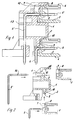
- Figur 1
- einen Schnitt durch eine doppelstöckige, mehrpolige Anschlußstiftleiste gemäß der Erfindung,
Figur 2- die in der Schnittdarstellung nach Figur 1 zu sehenden Teile der Anschlußstiftleiste in sprengbildlicher Darstellung,
Figur 3- eine doppelstöckige, mehrpolige Anschlußstiftleiste gemäß der Erfindung in sprengbildlicher Darstellung und in Perspektive von der Frontseite her,
- Figur 4
- eine weitere sprengbildliche Darstellung einer derartigen Anschlußstiftleiste in Perspektive von der Rückseite her,
Figur 5- eine fertig zusammengesetzte Anschlußstiftleiste in Perspektive von der Rückseite her,
Figur 6- die Anschlußstiftleiste nach
Figur 5 in Perspektive von der Frontseite her.
- Figure 1
- 2 shows a section through a double-decker, multi-pole connector pin strip according to the invention,
- Figure 2
- the parts of the connector pin seen in the sectional view of Figure 1 in an exploded view,
- Figure 3
- a two-storey, multi-pin connector pin strip according to the invention in an exploded view and in perspective from the front,
- Figure 4
- another exploded view of such a pin header in perspective from the back,
- Figure 5
- a ready assembled connector pin in perspective from the back,
- Figure 6
- 5 in perspective from the front.
Die erfindungsgemäße doppelstöckige, mehrpolige Anschlußstiftleiste
beinhaltet ein Trägergehäuse 1 aus elektrisch isolierendem Kunststoff,
das doppelstöckig ausgebildet ist, also zwei Etagen hat, wobei sich
injeder Etage jeweils eine Steckaufnahme 2 bzw. 3 befindet. Diese Steckaufnahmen
2 und 3 sind so konfiguriert, daß darin handelsübliche
einstöckige Anschlußstiftleisten 4 mit ihren Gehäusen 5 eingesetzt
werden können. Im Hinblick auf die Formen der Gehäuse 5 handelsüblicher
Anschlußstiftleisten 4 können die Steckaufnahmen 2 und 3 unkompliziert,
insbesondere von der Werkzeugseite her ohne die Verwendung von Steckgesichtkernen,
hergestellt werden.The double-decker, multi-pin connector strip according to the invention
includes a carrier housing 1 made of electrically insulating plastic,
which is two-story, so has two floors, with each other
There is a
In dem in den Figuren dargestellten Ausführungsbeispiel ist die Steckaufnahme
2 der unteren Etage des-Trägergehäuses 1 nach unten und zur
Frontseite der doppelstöckigen Anschlußstiftleiste offen. Darin kann
eine erste handelsübliche, einstöckige Anschlußstiftleiste 4 mit ihrem
Gehäuse 5 eingesetzt werden. Im dargestellten Ausführungsbeispiel findet
eine Anschlußstiftleiste 4 mit abgewinkelten Anschlußstiften 6 Verwendung.
Die abgewinkelten Anschlußstifte stellen somit die leitende
Verbindung und die Verbindungsmöglichkeit beispielsweise zu einer
Leiterplatte dar, sowie andererseits auch die Anschlußmöglichkeit für
einen anzuschließenden, in dieser Anschlußstiftleiste 4 einzusetzenden
Steckverbinder entsprechender Polzahl oder ein Steckverbindersystem
mit entsprechender Gesamtpolzahl.In the embodiment shown in the figures, the plug receptacle is
2 of the lower floor of the carrier housing 1 down and to
The front of the double-level pin header is open. In it can
a first commercial, single-level connector 4 with your
Die handelsüblichen Anschlußstiftleisten 4 haben rückseitig Steckverbinderelemente
7, die in ihrer Nebeneinanderanordnung zwischen sich
T-Nuten 8 definieren. Im dargestellten Ausführungsbeispiel sind in
der Steckaufnahme 2 in der unteren Etage des Trägergehäuses 1 zu diesen
T-Nuten 8 passende T-Stücke 9 gebildet, die in ihrer Längserstreckung
nach unten orientiert sind, so daß bei Einsteckung der Anschlußstiftleiste
4 von unten in die Steckaufnahme 2 des Trägergehäuses 1 diese
T-Stücke 9 in die T-Nuten 8 eintreten können und damit zur Frontseite
und damit Steckverbindungsrichtung bezüglich der abgewinkelten Anschlußstifte
6 hin eine stabile, formschlüssige Verriegelung gegeben ist.The commercially available pin headers 4 have connector elements on the
In weiterer zweckmäßiger Ausgestaltung sind zur klemmend stabilen Festlegung
des Gehäuses 5 der Anschlußstiftleiste 4 in Steckrichtung, also
nach unten hin, auf beiden Seiten in den Endbereichen auf jeweils
einigen T-Stücken 9 Klemmwulste 10 vorgesehen, die sich am gegenüberliegenden
Gehäusebereich des Gehäuses 5 im Bereich der T-Nuten 8 verklemmen.
Die Zahl der Klemmwulste 10 kann mit der Größe der zu erwartenden
Belastung, insbesondere auch Rüttelbelastung variieren.
Im Bedarfsfall können auf allen T-Stücken 9 Klemmwulste 10 vorgesehen
werden.In a further expedient embodiment, the clamping is stable and stable
of the
In den Figuren 2 und 3 ist aus Illustrationsgründen im Sprengbild auch
der abgewinkelte Anschlußstift 6 für die untere Anschlußleiste 4 als
Einzelteil mit entsprechende Steckrichtung gezeigt. In der Praxis
werden jedoch die handelsüblich mit diesen abgewinkelten Anschlußstiften
6 bestückten Anschlußstiftleisten 4 in ihrer Gesamtheit in
einem Arbeitsgang in die untere Steckaufnahme 2 des Trägergehäuses
1 eingesteckt, wie es in Figur 4 illustriert ist. In Figures 2 and 3 is also for reasons of illustration in the explosive
the
In zweckmäßiger Ausgestaltung ist die Steckaufnahme 3 des Trägergehäuses
1 in der oberen Etage ein zur Frontseite offener Schacht. In diesen
wird, wie in den.Figuren illustriert, zunächst nur das Gehäuse 5 einer
handelsüblichen Anschlußleiste 4, und zwar von der Frontseite her, eingesetzt.
Auch in der oberen Etage dienen die, die T-Nuten 8 bildenden
Steckverbinderelemente 7 an der Rückseite des Gehäuses 5 der Anschlußstiftleiste
4 der formschlüssigen Festsetzung in der schachtförmigen
Steckaufnahme 3 des Trägerrgehäuses 1. Es sind ferner auf der Innenfläche
der oberen Schachtwand 11 des Trägergehäuses 1 in einer der
Anzahl der T-Nuten 8 entsprechenden Anzahl kleine, ein wenig vorspringende
Raststücke 12 vorgesehen. Die obere Schachtwand 11 ist dabei
aufgrund ihrer Ausgestaltung insgesamt ein klein wenig verformbar.
Beim Einstecken des Gehäuses 5 können von daher die Raststücke 12 von
oben in die Querschenkel der T-Nuten 8 einschnappen, wie insbesondere
in Figur 1 gezeigt.In an expedient embodiment, the plug-in
Die doppelstöckige Anschlußstiftleiste wird dadurch fertigmontiert,
daß nach Einbringen des Gehäuses 5 in die obere Steckaufnahme 3 des
Trägergehäuses 1 nun im Hinblick auf die Bestückung der oberen Etage
entsprechend lange, abgewinkelte Anschlußstifte 6' durch entsprechende
Aussparungen im Trägergehäuse 1 hindurch in das Gehäuse 5 der Anschlußstiftleiste
4 zu deren Komplettierung eingesteckt werden. Für den nach
unten weisenden Bereich der Anschlußstifte 6' sind dabei rückwärtig
im Trägergehäuse 1 entsprechende Aufnahmen 13 vorgesehen. Die Anschlußstifte
6' haben den üblichen Klemmwulst 14, mit dem sie in einem entsprechenden
aufnehmenden Bereich des Stiftleistengehäuses 5 fest verklemmt
werden können.The double-level pin header is then fully assembled,
that after inserting the
Im dargestellten Ausführungsbeispiel ist eine doppelstöckige, mehrpolige
Anschlußstiftleiste vorgesehen, bei der in den beiden Etagen die beiden
handelsüblichen, einstöckigen Anschlußstiftleisten 4 mit ihren Gehäusen
5 im wesentlichen in einer Ebene übereinanderliegen.In the illustrated embodiment, a two-story, multi-pole
Terminal strip provided, in which the two in the two floors
commercially available, single-level connector strips 4 with their
In Abwandlung dieser Ausführungsform ist es bei entsprechender
Gestaltung des Trägergehäuses ohne weiteres möglich, die Steckaufnahmen
2 und 3 in den beiden Etagen treppenartig zueinander zu
versetzen, so daß dann auch die Anschlußstiftleisten 4 in der oberen
und unteren Etage treppenartig zueinander versetzt liegen, wie es bei
doppelstöckigen, mehrpoligen Anschlußstiftleisten bekannt ist.In a modification of this embodiment, it is corresponding
Design of the carrier housing possible without further ado, the plug-in
Es ist ferner in weiterer Abwandlung ohne weiteres möglich, das Trägergehäuse
1 bezüglich der Steckaufnahmen 2 und 3 so zu gestalten, daß in
den beiden Etagen die Anschlußstifte 6, 6' der Anschlußstiftleisten
versetzt zueinander auf Lücke liegen, wie es ebenfalls bei doppelstökkigen,
mehrpoligen Anschlußstiftleisten bekannt ist.It is also possible in a further modification without further ado, the carrier housing
1 with regard to the plug-in
Schließlich ist hervorzuheben, daß durchaus nicht in der oberen oder
unteren Etage des Trägergehäuses 1 Anschlußstiftleisten gleicher Polzahl
eingesetzt werden müssen. Die Steckaufnahmen 2 und 3 sind seitlich
offen und können somit handelsübliche, einstöckige Anschlußstiftleisten
4 aufnehmen, deren Polzahl deutlich größer als die Polzahl
des Trägergehäuses 1 ist. Von daher kann die Polzahl der Anschlußstiftleisten
4 von Etage zu Etage auch variieren.Finally, it should be emphasized that not at all in the upper or
lower level of the carrier housing 1 connector strips with the same number of poles
must be used. The
Claims (8)
- A double-level, multi-pole connecting pin strip having electrical connections which are disposed in the two levels and a casing of electrically insulating plastics material, characterised by a carrier casing (1) having a respective plug receiving means (2 and 3 respectively) in each level, into each of which respective single-level connecting pin strips (4) are fitted with their casings (5), wherein the one single-level connecting pin strip (4) with angled connecting pins (6) can firstly be fitted in the lower plug receiving means (2) and in the upper plug receiving means (3) after the casing (5) of the connecting pin strip (4) is fitted into the plug receiving means (3) angled connecting pins (6') can be fitted into the casing (5) of the connecting pin strip (4).
- A double-level connecting pin strip according to claim 1 characterised in that the plug receiving means (2) of the carrier casing (1) is open downwardly and towards the front side in the lower level.
- A double-level connecting pin strip according to one of the preceding claims characterised in that the plug receiving means (3) of the carrier casing (1) in the upper level is a shaft which is open towards the front side and into which the casing (5) of a single-level connecting pin strip (4) is inserted from the front side, wherein angled connecting pins (6') are fitted from the rear side into the casing (5) of the single-level connecting pin strip (4) and into receiving means (13) of the carrier casing (1).
- A double-level connecting pin strip according to one of the preceding claims characterised in that provided in the plug receiving means (2 and 3) of the carrier casing (1) are plug connection and positively-locking elements (9, 12) for fixing the casings (5) of the connecting pin strips (4).
- A double-level connecting pin strip according to claim 4 characterised in that provided in the lower plug receiving means (2) of the carrier casing (1) are downwardly extending T-portions (9) which are in engagement with T-shaped grooves (8) formed at the rear on the casing (5) of the connecting pin strip (4) by a succession of plug connector elements (7).
- A double-level connecting pin strip according to claim 5 characterised in that clamping ridges (10) are provided at least on some T-portions (9) in the plug receiving means (2) of the carrier casing (1).
- A double-level connecting pin strip according to claim 4 characterised in that provided on the inside surface of the upper shaft wall (11) of the upper plug receiving means (3) of the carrier casing (1) are retaining portions (12) which when the casing (5) of the connecting pin strip (4) is inserted are latched in T-shaped grooves (8) which are formed on the casing (5) by a succession of plug connector elements (7).
- A double-level connecting pin strip according to one of the preceding claims characterised in that the upper and lower plug receiving means (2 and 3) of the carrier casing (1) are kept open at the carrier casing end sides.
Applications Claiming Priority (2)
| Application Number | Priority Date | Filing Date | Title |
|---|---|---|---|
| DE9417390U DE9417390U1 (en) | 1994-10-20 | 1994-10-20 | Two-tier, multi-pin connector |
| DE9417390U | 1994-10-29 |
Publications (2)
| Publication Number | Publication Date |
|---|---|
| EP0709918A1 EP0709918A1 (en) | 1996-05-01 |
| EP0709918B1 true EP0709918B1 (en) | 1998-10-14 |
Family
ID=6915472
Family Applications (1)
| Application Number | Title | Priority Date | Filing Date |
|---|---|---|---|
| EP95113808A Expired - Lifetime EP0709918B1 (en) | 1994-10-20 | 1995-09-02 | Double row multipolar terminal block |
Country Status (4)
| Country | Link |
|---|---|
| EP (1) | EP0709918B1 (en) |
| AT (1) | ATE172328T1 (en) |
| DE (2) | DE9417390U1 (en) |
| ES (1) | ES2123194T3 (en) |
Cited By (1)
| Publication number | Priority date | Publication date | Assignee | Title |
|---|---|---|---|---|
| US9078695B2 (en) | 2009-06-05 | 2015-07-14 | Ethicon Endo-Surgery, Inc. | Methods and devices for accessing a body cavity using a surgical access device with modular seal components |
Families Citing this family (3)
| Publication number | Priority date | Publication date | Assignee | Title |
|---|---|---|---|---|
| US6095826A (en) * | 1997-02-21 | 2000-08-01 | Berg Technology, Inc. | Press fit circuit board connector |
| JPH118027A (en) * | 1997-06-13 | 1999-01-12 | Sumitomo Wiring Syst Ltd | Connector for substrate |
| DE102012016305A1 (en) | 2012-08-16 | 2014-05-15 | GSN Corporation GmbH & Co. KG | Plug-in connector i.e. electrical plug-in connector, for achieving electrical plug-in connection with stylus contacts, has plug connected to another plug, and contact stripes designed as section of single-piece supporting part |
Family Cites Families (2)
| Publication number | Priority date | Publication date | Assignee | Title |
|---|---|---|---|---|
| DE8009238U1 (en) * | 1980-04-02 | 1980-08-14 | Weco Wester, Ebbinghaus & Co, 6450 Hanau | Two-tier terminal block |
| DE9211314U1 (en) * | 1992-08-22 | 1992-10-29 | RIA electronic Albert Metz, 7712 Blumberg | Multi-pole terminal block |
-
1994
- 1994-10-20 DE DE9417390U patent/DE9417390U1/en not_active Expired - Lifetime
-
1995
- 1995-09-02 EP EP95113808A patent/EP0709918B1/en not_active Expired - Lifetime
- 1995-09-02 AT AT95113808T patent/ATE172328T1/en not_active IP Right Cessation
- 1995-09-02 ES ES95113808T patent/ES2123194T3/en not_active Expired - Lifetime
- 1995-09-02 DE DE59503919T patent/DE59503919D1/en not_active Expired - Lifetime
Cited By (1)
| Publication number | Priority date | Publication date | Assignee | Title |
|---|---|---|---|---|
| US9078695B2 (en) | 2009-06-05 | 2015-07-14 | Ethicon Endo-Surgery, Inc. | Methods and devices for accessing a body cavity using a surgical access device with modular seal components |
Also Published As
| Publication number | Publication date |
|---|---|
| ES2123194T3 (en) | 1999-01-01 |
| DE9417390U1 (en) | 1994-12-15 |
| DE59503919D1 (en) | 1998-11-19 |
| ATE172328T1 (en) | 1998-10-15 |
| EP0709918A1 (en) | 1996-05-01 |
Similar Documents
| Publication | Publication Date | Title |
|---|---|---|
| DE3587796T2 (en) | Modular block and electrical assembly systems using it. | |
| DE3709903C3 (en) | ELECTRIC CONNECTOR | |
| DE69204754T2 (en) | Terminal block for printed circuit boards. | |
| DE3783692T2 (en) | MODULAR ELECTRICAL CONNECTOR. | |
| DE69502190T2 (en) | DATA TRANSFER CONNECTOR | |
| DE102017119287B4 (en) | Modular connector for printed circuit boards | |
| EP3033808A1 (en) | Holding frame for plug connectors | |
| DE3903839A1 (en) | MOVABLE CONNECTOR | |
| DE102006003752A1 (en) | clutch | |
| DE29508095U1 (en) | Modular connector system | |
| EP0397057A1 (en) | Assembly for the mechanical and electrical connection of an extension circuit board to a mother circuit board | |
| DE2001690B2 (en) | Relay socket | |
| DE3026247C2 (en) | Housing made of insulating material, which can be lined up one behind the other and accommodates a plurality of electronic components, for mounting on a common base or mounting rail | |
| DE4001104A1 (en) | Plug connector for PCB - is flexible enough to allow interchanging of connection arrangement and connected elements | |
| DE2338778B2 (en) | Female connector | |
| DE102021116837A1 (en) | Terminal block and method of manufacturing the terminal block | |
| DE2615353C3 (en) | Electrical connector | |
| DE19724581A1 (en) | Socket for printed circuit boards | |
| EP0709918B1 (en) | Double row multipolar terminal block | |
| DE69603884T2 (en) | Device for mounting a lamp | |
| WO2000013264A1 (en) | Modular bus bar | |
| DE2802643C2 (en) | ||
| EP1445840B1 (en) | Electrical Connector | |
| DE2513640B2 (en) | Multipole coded connector | |
| DE102004019032B4 (en) | Electrical circuit board connector |
Legal Events
| Date | Code | Title | Description |
|---|---|---|---|
| PUAI | Public reference made under article 153(3) epc to a published international application that has entered the european phase |
Free format text: ORIGINAL CODE: 0009012 |
|
| AK | Designated contracting states |
Kind code of ref document: A1 Designated state(s): AT CH DE ES FR GB IT LI |
|
| 17P | Request for examination filed |
Effective date: 19960529 |
|
| 17Q | First examination report despatched |
Effective date: 19970421 |
|
| GRAG | Despatch of communication of intention to grant |
Free format text: ORIGINAL CODE: EPIDOS AGRA |
|
| GRAG | Despatch of communication of intention to grant |
Free format text: ORIGINAL CODE: EPIDOS AGRA |
|
| GRAH | Despatch of communication of intention to grant a patent |
Free format text: ORIGINAL CODE: EPIDOS IGRA |
|
| ITF | It: translation for a ep patent filed | ||
| GRAH | Despatch of communication of intention to grant a patent |
Free format text: ORIGINAL CODE: EPIDOS IGRA |
|
| GRAA | (expected) grant |
Free format text: ORIGINAL CODE: 0009210 |
|
| AK | Designated contracting states |
Kind code of ref document: B1 Designated state(s): AT CH DE ES FR GB IT LI |
|
| REF | Corresponds to: |
Ref document number: 172328 Country of ref document: AT Date of ref document: 19981015 Kind code of ref document: T |
|
| REG | Reference to a national code |
Ref country code: CH Ref legal event code: NV Representative=s name: ISLER & PEDRAZZINI AG Ref country code: CH Ref legal event code: EP |
|
| REF | Corresponds to: |
Ref document number: 59503919 Country of ref document: DE Date of ref document: 19981119 |
|
| REG | Reference to a national code |
Ref country code: ES Ref legal event code: FG2A Ref document number: 2123194 Country of ref document: ES Kind code of ref document: T3 |
|
| GBT | Gb: translation of ep patent filed (gb section 77(6)(a)/1977) |
Effective date: 19981229 |
|
| ET | Fr: translation filed | ||
| PLBE | No opposition filed within time limit |
Free format text: ORIGINAL CODE: 0009261 |
|
| STAA | Information on the status of an ep patent application or granted ep patent |
Free format text: STATUS: NO OPPOSITION FILED WITHIN TIME LIMIT |
|
| 26N | No opposition filed | ||
| REG | Reference to a national code |
Ref country code: GB Ref legal event code: IF02 |
|
| REG | Reference to a national code |
Ref country code: CH Ref legal event code: PCAR Free format text: ISLER & PEDRAZZINI AG;POSTFACH 1772;8027 ZUERICH (CH) |
|
| PGFP | Annual fee paid to national office [announced via postgrant information from national office to epo] |
Ref country code: ES Payment date: 20090922 Year of fee payment: 15 |
|
| PGFP | Annual fee paid to national office [announced via postgrant information from national office to epo] |
Ref country code: GB Payment date: 20090922 Year of fee payment: 15 Ref country code: CH Payment date: 20090923 Year of fee payment: 15 Ref country code: AT Payment date: 20090916 Year of fee payment: 15 |
|
| PGFP | Annual fee paid to national office [announced via postgrant information from national office to epo] |
Ref country code: IT Payment date: 20100922 Year of fee payment: 16 |
|
| REG | Reference to a national code |
Ref country code: CH Ref legal event code: PL |
|
| GBPC | Gb: european patent ceased through non-payment of renewal fee |
Effective date: 20100902 |
|
| PG25 | Lapsed in a contracting state [announced via postgrant information from national office to epo] |
Ref country code: LI Free format text: LAPSE BECAUSE OF NON-PAYMENT OF DUE FEES Effective date: 20100930 Ref country code: CH Free format text: LAPSE BECAUSE OF NON-PAYMENT OF DUE FEES Effective date: 20100930 |
|
| PG25 | Lapsed in a contracting state [announced via postgrant information from national office to epo] |
Ref country code: GB Free format text: LAPSE BECAUSE OF NON-PAYMENT OF DUE FEES Effective date: 20100902 Ref country code: AT Free format text: LAPSE BECAUSE OF NON-PAYMENT OF DUE FEES Effective date: 20100902 |
|
| REG | Reference to a national code |
Ref country code: ES Ref legal event code: FD2A Effective date: 20111019 |
|
| PG25 | Lapsed in a contracting state [announced via postgrant information from national office to epo] |
Ref country code: ES Free format text: LAPSE BECAUSE OF NON-PAYMENT OF DUE FEES Effective date: 20100903 |
|
| PGFP | Annual fee paid to national office [announced via postgrant information from national office to epo] |
Ref country code: DE Payment date: 20110923 Year of fee payment: 17 Ref country code: FR Payment date: 20110928 Year of fee payment: 17 |
|
| REG | Reference to a national code |
Ref country code: FR Ref legal event code: ST Effective date: 20130531 |
|
| PG25 | Lapsed in a contracting state [announced via postgrant information from national office to epo] |
Ref country code: DE Free format text: LAPSE BECAUSE OF NON-PAYMENT OF DUE FEES Effective date: 20130403 |
|
| PG25 | Lapsed in a contracting state [announced via postgrant information from national office to epo] |
Ref country code: FR Free format text: LAPSE BECAUSE OF NON-PAYMENT OF DUE FEES Effective date: 20121001 Ref country code: IT Free format text: LAPSE BECAUSE OF NON-PAYMENT OF DUE FEES Effective date: 20120902 |
|
| REG | Reference to a national code |
Ref country code: DE Ref legal event code: R119 Ref document number: 59503919 Country of ref document: DE Effective date: 20130403 |