EP0709533A2 - Schliesszylinder mit elektromagnetisch betätigbarem Sperrstift - Google Patents
Schliesszylinder mit elektromagnetisch betätigbarem Sperrstift Download PDFInfo
- Publication number
- EP0709533A2 EP0709533A2 EP95116755A EP95116755A EP0709533A2 EP 0709533 A2 EP0709533 A2 EP 0709533A2 EP 95116755 A EP95116755 A EP 95116755A EP 95116755 A EP95116755 A EP 95116755A EP 0709533 A2 EP0709533 A2 EP 0709533A2
- Authority
- EP
- European Patent Office
- Prior art keywords
- pin
- lock cylinder
- locking
- housing
- particular according
- Prior art date
- Legal status (The legal status is an assumption and is not a legal conclusion. Google has not performed a legal analysis and makes no representation as to the accuracy of the status listed.)
- Granted
Links
- 238000003780 insertion Methods 0.000 claims description 9
- 230000037431 insertion Effects 0.000 claims description 9
- 230000004913 activation Effects 0.000 claims description 3
- 230000005540 biological transmission Effects 0.000 claims description 2
- 239000004020 conductor Substances 0.000 claims 1
- 238000007654 immersion Methods 0.000 claims 1
- 238000011161 development Methods 0.000 description 2
- 230000018109 developmental process Effects 0.000 description 2
- 230000000694 effects Effects 0.000 description 2
- 230000001681 protective effect Effects 0.000 description 2
- 229910000831 Steel Inorganic materials 0.000 description 1
- 238000013459 approach Methods 0.000 description 1
- 238000013475 authorization Methods 0.000 description 1
- 230000008859 change Effects 0.000 description 1
- 230000000295 complement effect Effects 0.000 description 1
- 238000006073 displacement reaction Methods 0.000 description 1
- 230000005284 excitation Effects 0.000 description 1
- 230000010354 integration Effects 0.000 description 1
- 239000002184 metal Substances 0.000 description 1
- 238000000034 method Methods 0.000 description 1
- 230000008569 process Effects 0.000 description 1
- 230000004044 response Effects 0.000 description 1
- 239000011343 solid material Substances 0.000 description 1
- 239000010959 steel Substances 0.000 description 1
- 239000013589 supplement Substances 0.000 description 1
Images


Classifications
-
- E—FIXED CONSTRUCTIONS
- E05—LOCKS; KEYS; WINDOW OR DOOR FITTINGS; SAFES
- E05B—LOCKS; ACCESSORIES THEREFOR; HANDCUFFS
- E05B47/00—Operating or controlling locks or other fastening devices by electric or magnetic means
- E05B47/06—Controlling mechanically-operated bolts by electro-magnetically-operated detents
- E05B47/0611—Cylinder locks with electromagnetic control
- E05B47/0619—Cylinder locks with electromagnetic control by blocking the rotor
- E05B47/0626—Cylinder locks with electromagnetic control by blocking the rotor radially
- E05B47/063—Cylinder locks with electromagnetic control by blocking the rotor radially with a rectilinearly moveable blocking element
-
- E—FIXED CONSTRUCTIONS
- E05—LOCKS; KEYS; WINDOW OR DOOR FITTINGS; SAFES
- E05B—LOCKS; ACCESSORIES THEREFOR; HANDCUFFS
- E05B47/00—Operating or controlling locks or other fastening devices by electric or magnetic means
- E05B47/0001—Operating or controlling locks or other fastening devices by electric or magnetic means with electric actuators; Constructional features thereof
- E05B47/0002—Operating or controlling locks or other fastening devices by electric or magnetic means with electric actuators; Constructional features thereof with electromagnets
- E05B47/0003—Operating or controlling locks or other fastening devices by electric or magnetic means with electric actuators; Constructional features thereof with electromagnets having a movable core
- E05B47/0004—Operating or controlling locks or other fastening devices by electric or magnetic means with electric actuators; Constructional features thereof with electromagnets having a movable core said core being linearly movable
Definitions
- the invention relates to a locking cylinder according to the preamble of claim 1.
- Such a locking cylinder is known from the published patent application 41 26 160.
- the known locking cylinder has pin tumblers that interact with the profile of the key and consist of a core pin and a housing pin.
- the tumbler pins spring-loaded towards the housing are arranged by the notches in the key, so that with the correct key, the joints between the core pin and the housing pin are aligned with the core joint of the cylinder core.
- electronic coding is provided.
- electronically activatable elements of the key act together with a transmitting / receiving device which, if the electronic key coding is correct, releases an additional locking pin which protrudes into the cylinder core.
- the locking pin is parallel to the pin tumblers. The arrangement is space-consuming. Either a longer locking cylinder has to be provided or a mechanically codable pin tumbler has to be dispensed with.
- the object of the invention is to further develop a generic locking cylinder in a manner which is advantageous for use.
- the space requirement of the additional locking pin has been considerably minimized.
- the locking pin is preferably arranged in a hollow of the housing pin of the pin tumbler. It is advantageous if the locking pin is arranged in the tumbler which is furthest away from the key insertion opening. The possibility of manipulation is thus minimized. It is advantageous if the locking pin, which is guided coaxially in the housing pin, projects at one end in the locking position into an axial blind hole in the core pin.
- the additional locking pin can be cushioned.
- the spring of the locking pin can simultaneously be the cushioning of the housing pin of the associated pin tumbler.
- the locking pin preferably has a widened foot on which the said spring is supported.
- the base of the locking pin preferably interacts with an armature of an electromagnet which can be mounted parallel to the axial direction of the cylinder core.
- the armature can be displaced in the axial direction by applying current to the electromagnet or an actuating element having the same effect.
- the armature is preferably cylindrically symmetrical and has a large-diameter and a small-diameter area.
- the cross section of the armature can also have a shape that deviates from the cylindrical shape. This makes it possible to increase the stroke of the locking pin.
- the two areas with different diameters can be separated from one another by a frustoconical area.
- the locking pin can then be moved in the transverse direction by axially displacing the armature be shifted to the cylinder axis so that its front end is shifted into the cylinder core to achieve the locking effect, or is shifted out of the cylinder core to achieve the release position.
- the electromagnet is preferably arranged in a sleeve which is arranged in the flange area of the profile cylinder. The sleeve simultaneously forms the bottom of the housing bores in which the pin tumblers lie. This novel closure of the pin hole has its own meaning. Instead of the axially insertable sleeve, a bolt or the like made of solid material is also conceivable.
- the housing section with which the bores are closed then simultaneously forms a support surface for the pin springs.
- An antenna of a transmitter is preferably provided on the flange end, which cooperates with a transponder arranged in the cover of the key.
- a device for example a contact or the like, can also be provided in the area of the transmitter, which allows an emergency opening of the lock by, for example, coded actuation. The emergency opening can also be done mechanically.
- the transmitter which is to cooperate with the transponder arranged in the cover of the key, is preferably switched on by shifting the tumbler pin that was first shifted by the key during the insertion movement.
- the housing pin closest to the end face of the locking cylinder takes over the activation by a switching process.
- the transponder can have a magnet which interacts with a magnetic switch which is arranged in the sleeve.
- this pin tumbler is first shifted downwards.
- the approach of the magnet to the magnetic switch then causes the transmitter to start up and transmit signals to the transponder.
- the signals can be on a Carrier frequency be modulated.
- the carrier frequency can also represent the energy supply for the transponder at the same time.
- the signal received by the transponder which can also consist only of an electromagnetic carrier for energy transmission, causes the transponder to send a response signal to the locking cylinder. This signal then carries the coding.
- the antenna arranged in the flange area of the locking cylinder receives the signal emitted by the transponder and forwards it to an electronic circuit, which is preferably arranged outside the profile cylinder.
- an electronic circuit which is preferably arranged outside the profile cylinder.
- the signal received by the transponder is checked for the correct coding. If the coding is correct, the electromagnet is activated so that the locking pin is released. The latter can shift into the open position. When the key is removed, the locking pin is moved back into the locking position.
- the power supply for the additional electronic fuse can be formed by batteries or accumulators.
- the batteries and the accumulators as well as the electronic control circuit can be plugged into a pocket on the side of the door.
- the control electronics and battery holder are then behind the cuff.
- the cuff can be provided with a flap.
- This solution is particularly advantageous because the control electronics can only be accessed when the door is open. When the door is closed, adjustment elements such as switches arranged on the cuff are also not accessible for setting the locking combination.
- the control electronics arranged outside the locking cylinder is connected to the profile locking cylinder via a cable. It can be guided in a steel protective tube. The cable preferably emerges from an area which is located between the two cores of a double locking cylinder, out of the cylinder.
- the underside of the locking cylinder has a groove into which the cable can be inserted when the locking cylinder is inserted into the mortise lock.
- the cable then runs over the outer lock cover to the cuff-side compartment. Access to the electronic circuit can preferably only be possible with a programming key inserted into the locking cylinder. Without such activation, there is no authorization to change the coding or the like in the circuit.
- the electromagnet, a plunger anchor assigned to the electromagnet and the feed line are integrated in one assembly.
- this assembly should be insertable into a recess in the flange area of a profile locking cylinder.
- the assembly should preferably be insertable in the radial direction, so that tearing out of this assembly in the axial direction is prevented by correspondingly engaging projections.
- the assembly can be attached to the cylinder housing by means of screws and / or fastening pins.
- the outer wall of the assembly is intended to complement the recess for the profile shape of the locking cylinder.
- the longitudinal narrow edge of the flange section is to be formed, for example, by the assembly.
- the module should also carry a sensor that interacts with a magnetic housing pin.
- the sensor can be designed as a magnetically activatable switch and can be inserted into an opening when the assembly is inserted into the profile locking cylinder.
- the opening can be designed as a bore which runs parallel to the housing pin bore.
- the assembly is preferably formed by a carrier on which an antenna and the electromagnet are arranged, together with a plunger.
- the plunger anchor can have a guide slot, into which a projection of a pin that can be inserted into the longitudinal side opening of the carrier projects. As a result, the plunger anchor is non-rotatably mounted. The stroke of the locking pin can be maximized by appropriate gradations.
- the longitudinal narrow side of the profile cylinder, in particular the carrier is provided with a radially projecting projection.
- This projection serves as a so-called pull protection and interacts with a door plate which has a profile-adapted opening and is pushed with the opening over the locking cylinder.
- the opening, which is closed by the plug, is preferably aligned with the housing bore for the magnetically displaceable pin.
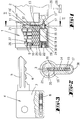
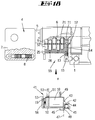
- the profile cylinder according to the invention has a housing 1, in which a closing member 2 is arranged.
- a closing member 2 is arranged.
- it is a double lock cylinder with two opposing cylinder cores 20.
- One of the cores 20 is equipped with an electromagnetically actuated locking pin 14.
- In the cylinder core 20 there are core pins 9 in transverse bores, which are classified by profiles 6 of a key 4.
- the profiles 6 consist of notches in the locking bit 5.
- the housing pins 10 arranged in the housing and aligned with the core pins 9 lie in bores 25.
- the bores are closed by the outer wall of a sleeve 24, which is inserted parallel to the axis of the core 20 in a corresponding opening in the profile section of the profile cylinder.
- the springs 26 are therefore supported on the sleeve wall.
- a total of six pin tumblers are provided, which are in a row.
- the first pin tumbler 9, 10 seen in the direction of insertion actuates a switch for a transmitter.
- the housing pin 10 has a magnet 27 on its end face facing the bottom of the bore 25, which magnet cooperates with a magnetic switch (not shown) arranged in the sleeve.
- the sleeve has an opening 23 through which the magnetic excitation of the magnetic switch can be achieved.
- the last tumbler 11, 12 in the insertion direction of the key 1 is provided with an additional locking pin 14.
- the core pin has a blind hole which is aligned with a through hole in the housing pin 12.
- the additional pin 14 is inserted into the bore made coaxially to the housing pin 12.
- the additional pin 14 has a foot 15 with an enlarged diameter.
- the diameter of the foot 15 corresponds to the diameter of the housing pin 10.
- the diameter of the additional pin 14 is less than the diameter of the pin bore.
- the housing base 15 is spring-loaded relative to the housing pin 10 by means of a spring 13 surrounding the pin 14, so that the pin tumbler 10, 11 is pressed in the core direction.
- the downwardly rounded foot 15 of the pin 14 rests on an armature 17 of an electromagnet 18.
- the armature 17 has a large-diameter area 17 'and a small-diameter area 17' '.
- the areas 17 ', 17' ' are separated from one another by a frustoconical ramp.
- the armature 17 can be displaced in the axial direction by actuating the electromagnet 18.
- the electromagnet 18 is arranged in said sleeve 24.
- an antenna 19 which interacts with a transponder arranged in the cover 7 of the key 8.
- an emergency opening 22 is provided, which can be operated manually or separately electrically in order to actuate the electromagnet or the armature if there is a fault in the electrical control or the batteries are empty.
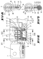
- a connecting cable 29 projecting approximately centrally from the profile area of the cylinder connects the antenna 19 and the electromagnet 18 with control electronics 39 and a transmitting part 38.
- the cable 29 has a plug 28 at the end.
- the transmitting part 38, the control electronics 39 and a battery compartment 40 are assigned to a separate housing 33, which is arranged below or above the mortise lock 37 behind the cuff in a slot in the door.
- the cuff 31 can be covered with a flap 32.
- the battery compartment 40 can be removed by opening the flap 32.
- a groove 30 is provided in the outer jacket area of the lock cylinder housing 1, into which the cable 29 can be inserted in certain areas.
- the energy is required for the transponder 8 to generate an electromagnetically coded signal sends back to the antenna.
- This signal which is picked up by the antenna 19, is evaluated in the control electronics 39. If this signal is a correct code, the electromagnet 18 is actuated. The anchor 17 is withdrawn.
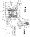
- the armature 17 In the position shown in Fig. 4, the armature 17 is still in the advanced position.
- the foot 15 of the locking pin 14 rests on the large-diameter section 17 'of the armature 17, so that the end face 16' of the locking end 16 of the locking pin 14 lies above the parting line 21 of the cylinder core 20.
- the locking position shown in FIG. 9 is a key with the correct mechanical coding, but with the wrong electronic coding.
- the signal emitted by the transponder 8 is not the right one.
- the armature 17 does not move back so that the foot 15 of the locking pin 14 rests on the larger diameter region 17 'of the armature 17.
- the locking end 16 projects with the end edge 16 ′ over the parting line 21 into the area of the core 20.
- the locking pin prevents rotation in this position of the locking cylinder.
- the lock cylinder cannot be turned.
- the compartment 33 which can be inserted into a separate opening on the narrow side of the door parallel to the mortise lock opening, is provided with a cover 32.
- the cover 32 runs parallel to the cuff 31 and is hinged to the cuff.
- insertion openings 36 are provided for batteries.
- a display device 34 is also provided, with which the coding or other lock parameters can be represented.
- the electronic closing parameters can be set by means of adjusting buttons 35. With the buttons 35, the coding of the lock can be changed in particular.
- the display 34 assigned to the cuff shows the current or changed locking code.
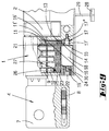
- FIGS. 13 to 18 functions essentially the same as the aforementioned embodiment. For this reason, the parts that function similarly or identically here are provided with the same reference numbers.
- a carrier 50 is provided, on which the magnet coil 18, the antenna 19, the plunger armature 17 and the feed line 47 are arranged. The whole forms an assembly 41.
- the antenna 19 is arranged in a plastic cap 56 and lies on the end face of the profile locking cylinder or the carrier 50.
- the assembly 41 can be inserted into a radial recess 55 of the profile locking cylinder housing 1.
- the carrier or the electromagnet 18 forms the bottom of the housing bores in which the housing pins 10 are movable and on which support the springs.
- the feed line 47 is guided in the joint between the recess 55 and the adjacent wall of the assembly group 41.
- the feed line is designed as a flexible strip line and extends as far as the antenna 19.
- the carrier 50 which is made of metal, forms pin extensions 49, which can be inserted in corresponding bores in the housing in the radial direction.
- the housing 1 forms a bore running parallel to the housing pin bores, in which an internal thread is cut, in which a fastening screw for the assembly 41 can be screwed.
- the locking cylinder housing 1 has a bore 57 into which a sensor 51 projects.
- the sensor 51 is connected to a flag of the feed line via contacts 53.
- the sensor is located below the housing pin, so that the housing pin is outside the sensor area when the key is not inserted.
- the sensor 51 is a magnetically activatable sensor which interacts with the magnetic first housing pin 52 as soon as a key is inserted and the pin 52 is moved downward into the sensor area.
- the plunger armature 17 emerging axially from the electromagnet 18 has a longitudinal groove 44 on its lower side. A projection of a stopper 45 engages in this longitudinal groove.
- the plunger anchor 17 is non-rotatably mounted.
- the flattened area 42 of the submersible anchor 17 can therefore have a sufficiently large spacing from the flattened area 43, which merges into the flat area 42 via an inclined step.
- the plug 45 is inserted into an opening of the carrier 50 and leaves a gap 48 between it and an adjacent projection 46, through which the feed line emerges.
- the projection 46 lies on the longitudinal narrow side of the profile locking cylinder and thus forms a pull guard.
- the projection 46 is supported to develop its protective effect against a fitting plate screwed on from the outside.
- the assembly 41 supplements the recess 55 to form a profile cylinder, in particular the longitudinal narrow side of the flange section is formed by the carrier 50. Because the carrier 50 can be inserted in the radial direction into the flange area of the locking cylinder, removal from the locking cylinder housing 1 is only possible when the locking cylinder has been removed.
- the assembly of all components relating to the additional electromagnetic locking device in one assembly simplifies assembly. It is particularly advantageous if the plug 45 closes an opening which is arranged in alignment with the electromagnetically actuated locking pin 14.
Landscapes
- Physics & Mathematics (AREA)
- Electromagnetism (AREA)
- Lock And Its Accessories (AREA)
- Turbine Rotor Nozzle Sealing (AREA)
- Mechanical Control Devices (AREA)
Abstract
Description
- Die Erfindung betrifft einen Schließzylinder gemäß Gattungsbegriff des Anspruchs 1.
- Ein derartiger Schließzylinder ist aus der Offenlegungsschrift 41 26 160 bekannt. Der bekannte Schließzylinder weist mit der Profilierung des Schlüssels zusammenwirkende, aus Kernstift und Gehäusestift bestehende Stiftzuhaltungen auf. Die zum Gehäuse hin abgefederten Zuhaltungsstifte werden durch die Kerben im Schlüssel eingeordnet, so daß bei dem richtigen Schlüssel die Trennfugen zwischen Kernstift und Gehäusestift mit der Kernfuge des Zylinderkerns fluchten. Zusätzlich zu dieser rein mechanischen Codierung des Schlüssels ist eine elektronische Codierung vorgesehen. Hierzu wirken elektronisch aktivierbare Elemente des Schlüssels zusammen mit einer Sende/Empfangsvorrichtung, welche bei richtiger elektronischer Schlüsselcodierung einen zusätzlichen Sperrstift, welcher in den Zylinderkern ragt, freigibt. Bei der bekannten Lösung liegt der Sperrstift parallel neben den Stiftzuhaltungen. Die Anordnung ist platzaufwendig. Es muß entweder ein längerer Schließzylinder vorgesehen werden oder auf eine mechanisch codierbare Stiftzuhaltung verzichtet werden.
- Ausgehend von diesem Stand der Technik liegt der Erfindung die Aufgabe zugrunde, einen gattungsgemäßen Schließzylinder gebrauchsvorteilhaft weiterzubilden.
- Gelöst wird die Aufgabe durch die im Anspruch 1 angegebene Erfindung.
- Unteransprüche stellen vorteilhafte Weiterbildungen der Erfindung dar.
- Zufolge der erfindungsgemäßen Ausgestaltung ist der Raumbedarf des zusätzlichen Sperrstiftes erheblich minimiert worden. Zufolge der Integration des Sperrstiftes in die Stiftzuhaltung kann die gesamte Länge des Einschubbereiches des Schlüssels zur mechanischen Codierung benutzt werde. Bevorzugt ist der Sperrstift in einer Höhlung des Gehäusestiftes der Stiftzuhaltung angeordnet. Es ist dabei von Vorteil, wenn der Sperrstift in dem der Schlüsseleinstecköffnung am weitest entfernt liegenden Zuhaltung angeordnet ist. Die Manipulationsmöglichkeit ist somit minimiert. Dabei ist es von Vorteil, wenn der koaxial im Gehäusestift geführte Sperrstift einendig in der Sperrstellung in eine axiale Sackbohrung des Kernstiftes ragt. Der zusätzliche Sperrstift kann abgefedert sein. Die Feder des Sperrstiftes kann gleichzeitig die Abfederung des Gehäusestiftes der zugeordneten Stiftzuhaltung sein. Der Sperrstift weist bevorzugt einen verbreiterten Fuß auf, auf welchem sich die besagte Feder abstützt. Der Fuß des Sperrstiftes wirkt bevorzugt mit einem parallel zur Achsrichtung des Zylinderkerns lagerbaren Anker eines Elektromagneten zusammen. Der Anker kann dabei durch Strombeaufschlagung des Elektromagneten oder eines gleichwirkenden Betätigungsorgans in Achsrichtung verlagert werden. Der Anker ist bevorzugt zylindersymmetrisch und weist einen durchmessergroßen und einen durchmessergeringen Bereich auf. Der Anker kann im Querschnitt auch ein von der zylindrischen abweichende Form aufweisen. Hierdurch ist eine Hubvergrößerung des Sperrstiftes möglich. Die beiden durchmesserunterschiedlichen Bereiche können durch einen kegelstumpfförmigen Bereich voneinander getrennt sein. Durch Axialverlagerung des Ankers kann dann der Sperrstift in Querrichtung zur Zylinderachse verlagert werden, damit sein Stirnende in den Zylinderkern hineinverlagert wird, zur Erzielung der Sperrwirkung, oder aus dem Zylinderkern herausverlagert wird, zur Erzielung der Freigabestellung. Der Elektromagnet ist bevorzugt in einer Hülse angeordnet, welche im Flanschbereich des Profilzylinders angeordnet ist. Dabei bildet die Hülse gleichzeitig den Boden der Gehäusebohrungen aus, in welchen die Stiftzuhaltungen einliegen. Dieser neuartige Verschluß der Stiftbohrung hat eigenständige Bedeutung. Anstelle der axial einsteckbaren Hülse ist auch ein Bolzen oder dergleichen aus Vollmaterial denkbar. Der Gehäuseabschnitt, mit welchem die Bohrungen verschlossen sind, bildet dann gleichzeitig eine Abstützfläche für die Stiftfedern aus. Flanschstirnseitig ist bevorzugt eine Antenne eines Senders vorgesehen, welcher mit einem in der Reide des Schlüssels angeordneten Transponders zusammenwirkt. Im Bereich des Senders kann ebenfalls eine Vorrichtung, beispielsweise ein Kontakt oder dergleichen vorgesehen sein, der durch beispielsweise codierte Betätigung eine Notöffnung des Schlosses erlaubt. Die Notöffnung kann auch mechanisch erfolgen. Der Sender, welcher mit dem in der Reide des Schlüssels angeordneten Transponder zusammenwirken soll, wird bevorzugt durch Verlagerung des vom Schlüssel bei der Einsteckbewegung zuerst verlagerten Zuhaltungsstift eingeschaltet. Der der Stirnfläche des Schließzylinders nächstgelegene Gehäusestift übernimmt die Aktivierung durch einen Schaltvorgang. Er kann hierzu einen Magneten aufweisen, welcher mit einem Magnetschalter zusammenwirkt, welcher in der Hülse angeordnet ist. Beim Einschieben des Schlüssels wird diese Stiftzuhaltung zuerst nach unten verlagert. Die Annäherung des Magneten an den Magnetschalter bewirkt dann, daß der Sender sich in Betrieb setzt und Signale an den Transponder überträgt. Die Signale können dabei auf eine Trägerfrequenz aufmoduliert sein. Die Trägerfrequenz kann dabei auch gleichzeitig die Energieversorgung für den Transponder darstellen. Das vom Transponder empfangene Signal, welches auch lediglich aus einem elektromagnetischen Träger zur Energieübertragung bestehen kann, bewirkt im Transponder die Aussendung eines Antwortsignales an den Schließzylinder. Dieses Signal trägt dann die Codierung. Die im Flanschbereich des Schließzylinders angeordnete Antenne empfängt das vom Tranponder ausgesandte Signal und leitet es an eine elektronische Schaltung weiter, welche bevorzugt außerhalb des Profilzylinders angeordnet ist. Dort wird das vom Transponder empfangene Signal auf die richtige Codierung überprüft. Bei richtiger Codierung wird der Elektromagnet aktiviert, so daß der Sperrstift freigegeben wird. Letzterer kann sich in die Öffnungsstellung verlagern. Bei Herausziehen des Schlüssels wird der Sperrstift wieder in die Verriegelungsstellung verlagert. Die Stromversorgung für die elektronische Zusatzsicherung kann durch Batterien oder Akkumulatoren gebildet sein. Die Batterien und die Akkumulatoren können ebenso wie die elektronische Steuerungsschaltung in eine stulpseitige Tasche der Tür eingesteckt werden. Steuerungselektronik und Batteriehalter liegen dann hinter der Stulpe. Um einen Zugriff zur Steuerungselektronik oder zum Batteriefach zu erhalten, kann die Stulpe mit einer Klappe versehen sein. Diese Lösung ist insbesondere deshalb von Vorteil, da auf die Steuerungselektronik nur bei geöffneter Tür zugegriffen werden kann. Bei geschlossener Tür sind auch stulpseitig angeordnete Verstellorgane, wie Schalter, zum Einstellen der Schließkombination nicht zugänglich. Die außerhalb des Schließzylinders angeordnete Steuerungselektronik ist mit dem Profilschließzylinder über ein Kabel verbunden. Es kann in einem einen Stahl-Schutzrohr geführt sein. Das Kabel tritt bevorzugt aus einem Bereich, welcher zwischen den beiden Kernen eines Doppelschließzylinders gelegen ist, aus dem Zylinder heraus. Damit das Kabel beim Einschieben des Profilschließzylinders in ein Einsteckschloß nicht abgeschert wird, weist die Unterseite des Schließzylinders eine Nut auf, in welche das Kabel eingelegt werden kann, wenn der Schließzylinder in das Einsteckschloß eingeschoben wird. Das Kabel läuft dann über die äußere Schloßdecke zu dem stulpseitigen Fach. Der Zugriff auf die elektronische Schaltung kann vorzugsweise nur bei einem in den Schließzylinder eingesteckten Programmier-Schlüssel möglich sein. Ohne eine derartige Aktivierung ist keine Berechtigung gegeben, die Codierung oder dergleichen in der Schaltung zu ändern.
- Ein auch eigenständiger Gedanke der Erfindung liegt darin, daß der Elektromagnet, ein dem Elektromagnet zugeordneter Tauchanker und die Zuleitung in einer Baugruppe integriert sind. Diese Baugruppe soll erfindungsgemäß in einer Aussparung des Flanschbereiches eines Profilschließzylinders einsteckbar sein. Bevorzugt soll die Baugruppe in radialer Richtung einsteckbar sind, so daß ein Herausreißen dieser Baugruppe in axialer Richtung durch entsprechend hintergriffene Vorsprünge gehindert ist. Die Baugruppe kann mittels Schrauben und/oder Befestigungsstiften am Zylindergehäuse befestigt sein. Die Außenwandung der Baugruppe soll die Aussparung zur Profilform des Schließzylinders ergänzen. Insbesondere soll die Längsschmalkante des Flanschabschnittes beispielsweise von der Baugruppe ausgebildet werden. Die Baugruppe soll ebenfalls einen Sensor tragen, welcher mit einem magnetischen Gehäusestift zusammenwirkt. Der Sensor kann dabei als magnetisch aktivierbarer Schalter ausgebildet sein und beim Einstecken der Baugruppe in den Profilschließzylinder in eine Öffnung gesteckt werden. Die Öffnung kann als Bohrung ausgestaltet sein, welche parallel zur Gehäusestiftbohrung verläuft. Bevorzugt wird die Baugruppe von einem Träger gebildet, auf welchem eine Antenne und der Elektromagnet nebst Tauchanker angeordnet sind. Der Tauchanker kann einen Führungsschlitz aufweisen, in welchen ein Vorsprung eines in die Längsseitenöffnung des Trägers einsteckbarer Zapfen ragt. Hierdurch ist der Tauchanker undrehbar gelagert. Durch entsprechende Abstufungen kann dadurch der Hub des Sperrstiftes maximiert werden. In einer besonderen Weiterbildung der Erfindung, die auch eigenständigen Charakter aufweist, ist die Längsschmalseite des Profilzylinders insbesondere der Träger mit einem radial ausragenden Vorsprung versehen. Dieser Vorsprung dient als sogenannter Ziehschutz und wirkt mit einem Türschild zusammen, das eine profilangepaßte Öffnung aufweist, und mit der Öffnung über den Schließzylinder geschoben wird. Die Öffnung, welche von dem Stopfen verschlossen wird, liegt bevorzugt fluchtend zur Gehäusebohrung für den magnetisch verlagerbaren Stift.
- Ausführungsbeispiele der Erfindung werden nachfolgend anhand beigefügter Zeichnungen erläutert. Es zeigt:
- Fig. 1
- ein erfindungsgemäßes Schloß, teilweise aufgebrochen, im Querschnitt,
- Fig. 2
- eine schnittgemäße Linie II-II in Fig. 1,
- Fig. 3
- einen zum Schloß gemäß Fig. 1 passenden Schlüssel,
- Fig. 4
- eine Darstellung gemäß Fig. 1 bei teilweise eingeschobenem Schlüssel,
- Fig. 5
- einen Schnitt gemäß der Linie V-V in Fig. 4,
- Fig. 6
- einen Profilzylinder bei vollständig eingeschobenem Schlüssel und richtiger elektronisch lesbarer Codierung,
- Fig. 7
- einen Schnitt gemäß der Linie VII-VII,
- Fig. 8
- einen Schnitt gemäß der Linie VIII-VIII,
- Fig. 9
- eine Darstellung gemäß Fig. 6 bei vollständig eingeschobenem Schlüssel aber falscher elektronisch lesbarer Codierung,
- Fig. 10
- ein Einsteckschloß mit eingesetztem Profilzylinder in Ansicht,
- Fig. 11
- ein stulpseitiges Einsteckfach zur Aufnahme der elektronischen Schaltung und der Batterien,
- Fig. 12
- eine Seitenansicht von Profilzylinder und Einsteckfach,
- Fig. 13
- ein zweites Ausführungsbeispiel der Erfindung, teils geschnitten,
- Fig. 14
- einen Schnitt gemäß der Linie XIV-XIV in Fig. 13,
- Fig. 15
- einen Schnitt gemäß der Linie XV-XV in Fig. 14,
- Fig. 16
- eine Darstellung gemäß Fig. 13 bei eingestecktem passenden Schlüssel,
- Fig. 17
- einen Schnitt gemäß der Linie XVII-XVII in Fig. 16, und
- Fig. 18
- eine Darstellung gemäß Fig. 16 bei nicht eingeschobenem Bausatz.
- Der erfindungsgemäße Profilzylinder weist ein Gehäuse 1 auf, in welchem ein Schließglied 2 angeordnet ist. Beim Ausführungsbeispiel handelt es sich um einen Doppelschließzylinder mit zwei gegenüberliegenden Zylinderkernen 20. Einer der Kerne 20 ist mit einem elektromagnetisch betätigbaren Sperrstift 14 ausgestattet. Im Zylinderkern 20 liegen in Querbohrungen Kernstifte 9, welche von Profilierungen 6 eines Schlüssels 4 eingeordnet werden. Die Profilierungen 6 bestehen aus Kerben des Schließbartes 5.
- Die im Gehäuse angeordneten, zu den Kernstiften 9 fluchtenden Gehäusestifte 10 liegen in Bohrungen 25 ein. Die Bohrungen werden verschlossen durch die Außenwand einer Hülse 24, welche parallel zur Achse des Kerns 20 in eine entsprechende Öffnung des Profilabschnittes des Profilzylinders eingesteckt ist. Die Federn 26 stützen sich demzufolge auf der Hülsenwandung ab.
- Im Ausführungsbeispiel sind insgesamt sechs Stiftzuhaltungen vorgesehen, welche in einer Reihe liegen. Die in Einsteckrichtung gesehen erste Stiftzuhaltung 9, 10 betätigt einen Einschalter für einen Sender. Hierzu weist der Gehäusestift 10 an seiner dem Boden der Bohrung 25 zugewandten Stirnseite einen Magneten 27 auf, welcher mit einem in der Hülse angeordneten Magnetschalter (nicht dargestellt) zusammenwirkt. Die Hülse weist hierzu eine Öffnung 23 auf, durch welche die magnetische Erregung des Magnetschalter erreichen kann.
- Die in Einsteckrichtung des Schlüssels 1 letzte Stiftzuhaltung 11, 12 ist mit einem zusätzlichen Sperrstift 14 versehen. Der Kernstift weist dazu eine Sackbohrung auf, welche mit einer durchgehenden Bohrung des Gehäusestiftes 12 fluchtet.
- In der koaxial zum Gehäusestift 12 eingebrachten Bohrung steckt der Zusatzstift 14. Der Zusatzstift 14 weist einen durchmesservergrößerten Fuß 15 auf. Der Durchmesser des Fußes 15 entspricht dem Durchmesser des Gehäusestiftes 10. Der Durchmesser des Zusatzstiftes 14 ist geringer als der Durchmesser der Stiftbohrung. Der Gehäusefuß 15 ist mittels einer den Stift 14 umgebenden Feder 13 gegenüber dem Gehäusestift 10 abgefedert, so daß die Stiftzuhaltung 10, 11 in Kernrichtung gedrückt wird. Der nach unten abgerundete Fuß 15 des Stiftes 14 ruht auf einem Anker 17 eines Elektromagneten 18. Der Anker 17 weist einen durchmessergroßen Bereich 17' und einen durchmesserkleinen Bereich 17'' auf. Die Bereiche 17', 17'' sind durch eine kegelstumpfförmige Auflaufschräge voneinander getrennt. Der Anker 17 ist durch Betätigung des Elektromagneten 18 in Achsrichtung verlagerbar.
- Der Elektromagnet 18 ist in besagter Hülse 24 angeordnet. Am Ende der Hülse, zur Stirnseite des Profils des Profilschließzylinders ragend, ist eine Antenne 19 angeordnet, welche mit einem in der Reide 7 des Schlüssels 8 angeordneten Transponders zusammenwirkt. Zusätzlich ist eine Notöffnung 22 vorgesehen, welche manuell oder gesondert elektrisch betreibbar ist, um den Elektromagneten bzw. den Anker zu betätigen, wenn eine Störung der elektrischen Steuerung vorliegt oder die Batterien leer sind.
- Eine etwa mittig aus dem Profilbereich des Zylinders herausragendes Anschlußkabel 29 verbindet die Antenne 19 und den Elektromagneten 18 mit einer Steuerungselektronik 39 und einem Sendeteil 38. Hierzu weist das Kabel 29 am Ende einen Stecker 28 auf. Das Sendeteil 38, die Steuerungselektronik 39 und ein Batteriefach 40 sind einem gesonderten Gehäuse 33 zugeordnet, welches unterhalb oder oberhalb des Einsteckschlosses 37 hinter der Stulpe in einem Einschubfach der Tür angeordnet ist. Die Stulpe 31 kann mit einer Klappe 32 verdeckt werden. Durch Öffnen der Klappe 32 kann das Batteriefach 40 herausgenommen werden.
- Damit das Kabel beim Einstecken des Profilschließzylinders in ein Einsteckschloß 37 nicht abschert, ist im äußeren Mantelbereich des Schließzylindergehäuses 1 eine Nut 30 vorgesehen, in welche das Kabel 29 bereichsweise eingelegt werden kann.
- Es ergibt sich folgende Funktionsweise:
Bei dem in Fig. 1 dargestellten Zustand sind die Zuhaltungsstifte 9, 10, 11, 12 nicht eingeordnet. Der Schließzylinderkern ist nicht drehbar. Beim Einstecken des Schlüssels 4 mit seinem Schließbart 5 in die Einstecköffnung 3 des Schließzylinders wird zunächst die erste Stiftzuhaltung 9, 10 nach unten verlagert. Einhergehend mit dieser Abwärtsverlagerung wird der Magnet 27 der Hülse 24 bzw. dem Boden der Bohrung angenähert. Ein dort angeordneter Magnetschalter signalisiert der Steuerungselektronik 39, daß ein Schlüssel eingesteckt werden soll. Die Steuerungselektronik 39 veranlaßt den Sender 38 über die Antenne 19 ein elektromagnetisches Signal auszustrahlen. Dieses elektromagnetische Signal wird vom Transponder 8 des Schlüssels 4 aufgenommen. Der Transponder 8 nimmt durch dem Emfang der elektromagnetischen Welle Energie auf. Die Energie wird dazu benötigt, daß der Transponder 8 ein elektromagnetisch codiertes Signal an die Antenne zurücksendet. Dieses von der Antenne 19 aufgefangene Signal wird in der Steuerungselektronik 39 ausgewertet. Handelt es sich bei diesem Signal um einen richtigen Code, so wird der Elektromagnet 18 betätigt. Der Anker 17 wird zurückgezogen. - In der in Fig. 4 dargestellten Stellung ist der Anker 17 noch in der vorgeschobenen Stellung. Der Fuß 15 des Sperrstiftes 14 ruht auf dem durchmessergroßen Abschnitt 17' des Ankers 17, so daß die Stirnfläche 16' des Sperrende 16 des Sperrstiftes 14 oberhalb der Trennfuge 21 des Zylinderkerns 20 liegt.
- Bei der in Fig. 6 dargestellten vollständigen Einschubstellung des Schlüssels fluchten die Trennfugen zwischen den Gehäusestiften 10, 12 und Kernstiften 9, 11 mit der Trennfuge 21. In dieser Stellung ist, wie erwähnt, der Anker 17 zurückgezogen, so daß der Fuß 15 des Sperrstiftes 14 auf dem durchmessergeringen Bereich 17'' des Ankers 17 ruht. Der Sperrstift 14 hat sich somit abwärts verlagert, so daß die Stirnkante 16' des Sperrendes 16 unterhalb der Trennfuge 21 liegt. In dieser Stellung läßt sich der Schlüssel drehen und der Profilzylinder betätigen.
- Bei der in Fig. 9 dargestellten Schließstellung handelt es sich um einen Schlüssel mit korrekter mechanischer Codierung, aber mit falscher elektronischer Codierung. Das vom Transponder 8 ausgesandte Signal ist nicht das richtige. In diesem Falle unterbleibt eine Rückverlagerung des Ankers 17, so daß der Fuß 15 des Sperrstiftes 14 auf dem durchmessergrößeren Bereich 17' des Ankers 17 ruht. Das Sperrende 16 ragt mit der Stirnkante 16' über die Trennfuge 21 in den Bereich des Kernes 20 hinein. Der Sperrstift verhindert in dieser Stellung eine Drehung des Schließzylinders. Der Schließzylinder läßt sich trotz richtiger mechanischer Codierung nicht drehen.
- Das im Bereich der Stulpe in eine parallel zur Einsteckschloßöffnung in eine gesonderte Öffnung der Schmalseite der Tür einsteckbare Fach 33 ist mit einer Abdeckung 32 versehen. Die Abdeckung 32 läuft parallel zur Stulpe 31 und ist an der Stulpe anscharniert. In Fig. 11 sind Einstecköffnungen 36 für Batterien vorgesehen. Es ist zudem eine Anzeigevorrichtung 34 vorgesehen, mit welcher die Codierung oder andere Schloßparameter darstellbar sind. Mittels Einstellknöpfen 35 lassen sich die elektronischen Schließparameter einstellen. Mit den Knöpfen 35 läßt sich insbesondere auch die Codierung des Schlosses ändern. Die der Stulpe zugeordnete Anzeige 34 zeigt den aktuellen oder geänderten Schließcode an.
- Die in den Fig. 13 bis 18 dargestellte Ausgestaltung eines Profilschließzylinders funktioniert im wesentlichen genauso wie das vorbezeichnete Ausführungsbeispiel. Deshalb sind die hier ähnlich oder gleich funktionierenden Teile mit gleichen Bezugsziffern versehen.
- Bei diesem Ausführungsbeispiel ist ein Träger 50 vorgesehen, auf welchem die Magnetspule 18, die Antenne 19, der Tauchanker 17 und die Zuleitung 47 angeordnet sind. Das Ganze bildet eine Baugruppe 41.
- Die Antenne 19 ist in einer Kunststoffkappe 56 angeordnet und liegt auf der Stirnseite des Profilschließzylinders, bzw. des Trägers 50. Die Baugruppe 41 ist in eine radiale Aussparung 55 des Profilschließzylindergehäuses 1 einschiebbar. Dabei bildet der Träger, bzw. der Elektromagnet 18 den Boden der Gehäusebohrungen, in welchen die Gehäusestifte 10 beweglich sind und an welchem sich die Federn abstützen. In der Fuge zwischen Aussparung 55 und angrenzender Wand der Raugruppe 41 ist die Zuleitung 47 geführt. Die Zuleitung ist als flexible Streifenleitung ausgebildet und reicht bis zur Antenne 19. Der Träger 50, welcher aus Metall gestaltet ist, bildet Stiftfortsätze 49 aus, welche in entsprechende Bohrungen des Gehäuses in radialer Richtung einsteckbar sind. Das Gehäuse 1 bildet eine parallel zu den Gehäusestiftbohrungen laufende Bohrung aus, in welcher ein Innengewinde eingeschnitten ist, in welcher eine Befestigungsschraube für die Baugruppe 41 einschraubbar ist. In paralleler Erstreckung, seitlich versetzt zum ersten Gehäusestift weist das Schließzylindergehäuse 1 eine Bohrung 57 auf, in welche ein Sensor 51 ragt. Der Sensor 51 ist über Kontakte 53 mit einer Fahne der Zuleitung verbunden. Der Sensor liegt unterhalb des Gehäusestiftes, so daß bei nicht eingeschobenem Schlüssel der Gehäusestift außerhalb des Sensorbereiches liegt. Bei dem Sensor 51 handelt es sich um einen magnetisch aktivierbaren Sensor, der mit dem magnetischen ersten Gehäusestift 52 zusammenwirkt, sobald ein Schlüssel eingeschoben wird und der Stift 52 nach unten in den Sensorbereich verlagert wird.
- Der aus dem Elektromagneten 18 axial austretende Tauchanker 17 weist an seiner unteren Seite eine Längsnut 44 auf. In diese Längsnut greift ein Vorsprung eines Stopfens 45. Hierdurch ist der Tauchanker 17 undrehbar gelagert. Die Abflachung 42 des Tauchankers 17 kann deshalb eine genügend große Beabstandung haben zur Abflachung 43, welche über eine schräge Stufe in die Abflachung 42 übergeht. Durch axiale Verlagerung des Tauchankers 17 wird der Sperrstift 14 in die Sperrstellung verlagert, in dieser Stellung wird der Sperrstift 14 von der Abflachung 43 beaufschlagt.
- Der Stopfen 45 ist in eine Öffnung des Träger 50 eingesteckt und beläßt zwischen sich und einem benachbart angeordneten Vorsprung 46 einen Spalt 48, durch welchen die Zuleitung heraustritt. Der Vorsprung 46 liegt im zusammengebauten Zustand an der Längsschmalseite des Profilschließzylinders und bildet so einen Ziehschutz. Der Vorsprung 46 stützt sich zur Entfaltung seiner Schutzwirkung gegen ein von außen angeschraubtes Beschlagschild. Die Baugruppe 41 ergänzt die Aussparung 55 zur Profilzylinderform, insbesondere wird die Längsschmalseite des Flanschabschnittes vom Träger 50 ausgebildet. Dadurch, daß der Träger 50 in radialer Richtung in den Flanschbereich des Schließzylinders einsteckbar ist, ist eine Entfernung vom Schließzylindergehäuse 1 nur bei ausgebautem Schließzylinder möglich. Die Zusammenfassung sämtlicher die elektromagnetische Zusatzzuhaltung betreffenden Bauteile in einer Baugruppe vereinfacht die Montage. Vorteilhaft ist insbesondere, wenn der Stopfen 45 eine Öffnung verschließt, welche fluchtend zu dem elektromagnetisch betätigbarem Sperrstift 14 angeordnet ist.
- Die in der vorstehenden Beschreibung, der Zeichnung und den Ansprüchen offenbarten Merkmale der Erfindung können sowohl einzeln als auch in beliebiger Kombination für die Verwirklichung der Erfindung von Bedeutung sein. Alle offenbarten Merkmale sind erfindungswesentlich. In die Offenbarung der Anmeldung wird hiermit auch der Offenbarungsinhalt der zugehörigen/beigefügten Prioritätsunterlagen (Abschrift der Voranmeldung) vollinhaltlich mit einbezogen.
Claims (24)
- Schließzylinder mit einem von mindestens einer schlüsselprofilgesteuerten Stiftzuhaltung (10, 11), welche einen Kernstift (11) und einen im Gehäuse abgefederten Gehäusestift (12) aufweist und einen elektromagnetisch betätigbaren Sperrstift (14), drehgesperrten Zylinderkern, dadurch gekennzeichnet, daß der Sperrstift in der Stiftzuhaltung (10, 11) integriert ist.
- Schließzylinder nach Anspruch 1 oder insbesondere danach, dadurch gekennzeichnet, daß der Sperrstift (14) in einer Bohrung des Gehäusestiftes (12) angeordnet ist.
- Schließzylinder nach einem oder mehreren der vorhergehenden Ansprüche oder insbesondere danach, dadurch gekennzeichnet, daß der koaxial im Gehäusestift (12) geführte Sperrstift (14) einendig in der Sperrstellung mit einem Sperrende (16) in eine axiale Sackbohrung (11') des Zylinderkernstiftes (11) ragt.
- Schließzylinder nach einem oder mehreren der vorhergehenden Ansprüche oder insbesondere danach, dadurch gekennzeichnet, daß sich die Feder (13) des dem Sperrstift (14) zugeordneten Gehäusestiftes (12) an einem Fuß (15) des Sperrstiftes (14) abstützt.
- Schließzylinder nach einem oder mehreren der vorhergehenden Ansprüche oder insbesondere danach, gekennzeichnet durch eine flanschstirnseitig in eine die Stiftbohrungen (25) kreuzende Bohrung des Schließzylindergehäuses (1) eingesteckte Hülse (24) oder dergleichen, auf deren die Stiftbohrungen verschließender Außenwandung sich die Federn (26) der Stiftzuhaltungen abstützen.
- Schließzylinder nach einem oder mehreren der vorhergehenden Ansprüche oder insbesondere danach, dadurch gekennzeichnet, daß der Sperrstift (14) von einem parallel zur Achsrichtung des Zylinderkerns (20) verlagerbaren Anker (17) eines Elektromagneten (18) gesteuert wird.
- Schließzylinder nach einem oder mehreren der vorhergehenden Ansprüche oder insbesondere danach, dadurch gekennzeichnet, daß der Elektromagnet (18) im Flanschbereich des Profilzylinders angeordnet ist.
- Schließzylinder nach einem oder mehreren der vorhergehenden Ansprüche oder insbesondere, dadurch gekennzeichnet, daß der Elektromagnet (18) in einer Hülse (24) sitzt, auf deren Außenfläche sich die Federn der Stiftzuhaltungen (9, 10) abstützen.
- Schließzylinder nach einem oder mehreren der vorhergehenden Ansprüche oder insbesondere danach, gekennzeichnet durch eine flanschseitige Antenne, welche von der Hülse aufgenommen wird.
- Schließzylinder nach einem oder mehreren der vorhergehenden Ansprüche oder insbesondere danach, gekennzeichnet durch einen in der Schlüsselreide (7) angeordneten mit der Antenne (19) zusammenwirkenden Transponder (8).
- Schließzylinder nach einem oder mehreren der vorhergehenden Ansprüche oder insbesondere danach, gekennzeichnet durch eine Aktivierung des Senders durch eine von dem Schlüssel verlagerte stiftzuhaltung (9, 10).
- Schließzylinder nach einem oder mehreren der vorhergehenden Ansprüche oder insbesondere danach, gekennzeichnet durch einen dem Gehäusestift (10) zugeordneten Magneten, welcher mit einem Magnetschalter zusammenwirkt.
- Schließzylinder nach einem oder mehreren der vorhergehenden Ansprüche oder insbesondere danach, gekennzeichnet durch eine am Zylindermantel vorgesehene Kabelführungsnut (30).
- Schließzylinder nach einem oder mehreren der vorhergehenden Ansprüche, gekennzeichnet durch ein von der Stulpe abgedecktes, in einer türschmalseitigen Öffnung einsteckbares Batteriefach.
- Schließzylinder nach einem oder mehreren der vorhergehenden Ansprüche oder insbesondere danach, gekennzeichnet durch ein in einer stulpseitigen Tasche eingestecktes Gehäuse, zur Aufnahme einer elektronischen Steuereinheit (39), welche auch einen Hochfrequenzsende- und -empfangsteil umfassen kann.
- Schließzylinder nach einem oder mehreren der vorhergehenden Ansprüche oder insbesondere danach, gekennzeichnet durch der Stulpe (31) zugeordnete, insbesondere mit einer Abdeckung (32) abdeckbare Umcodierschalter (35) und/oder eine Anzeigeeinrichtung (34).
- Schließzylinder mit einem von mindestens einer schlüsselprofilgesteuerten Stiftzuhaltung (10, 11), welche einen Kernstift (11) und einen im Gehäuse abgefederten Gehäusestift (12) aufweist und einen elektromagnetisch betätigbaren Sperrstift (14), drehgesperrten Zylinderkern, dadurch gekennzeichnet, daß der Elektromagnet (18), ein dem Elektromagneten zugeordneter Tauchanker (17) und eine Zuleitung (47) einer quer zur Schlüsseleinsteckrichtung in einer Aussparung (55) des Flanschbereiches des Profilschließzylinders einsteckbaren Baugruppe (41) zugeordnet sind.
- Schließzylinder nach einem oder mehreren der vorhergehenden Ansprüche oder insbesondere danach, dadurch gekennzeichnet, daß die Baugruppe einen mit dem Flanschabschnitt durch Radialstifte (49) verbindbaren Träger (50) umfaßt, dessen Auswandung die Aussparung (55) zur Profilform ergänzt.
- Schließzylinder nach einem oder mehreren der vorhergehenden Ansprüche oder insbesondere danach, dadurch gekennzeichnet, daß der Träger eine Sende-/Empfangsantenne (19) aufweist.
- Schließzylinder nach einem oder mehreren der vorhergehenden Ansprüche oder insbesondere danach, gekennzeichnet durch einen in einer parallelen Bohrung (57) zu den Gehäusestiftbohrungen angeordneten Sensor (51), welcher mit einem magnetischen Gehäusestift (52) zusammenwirkt.
- Schließzylinder nach einem oder mehreren der vorhergehenden Ansprüche oder insbesondere danach, dadurch gekennzeichnet, daß der eine Stufe ausbildende Tauchanker (17) einen Führungsschlitz (44) aufweist, in welchen ein Vorsprung eines in eine Längsschmalseitenöffnung des Trägers (50) einsteckbarer Stopfen (45) ragt.
- Schließzylinder nach einem oder mehreren der vorhergehenden Ansprüche oder insbesondere danach, dadurch gekennzeichnet, daß die als flexibler Streifenleiter ausgebildete Zuleitung (47) in dem von der Stirnseite des Profilschließzylinders abgewandten Bereich des Trägers (50) durch einen Spalt (48) austritt.
- Schließzylinder nach einem oder mehreren der vorhergehenden Ansprüche oder insbesondere danach, dadurch gekennzeichnet, daß der Spalt benachbart liegt zu einem an der Längsschmalseite des Trägers angebrachten Vorsprung (46) und von diesem türschildseitig abgedeckt wird.
- Schließzylinder nach einem oder mehreren der vorhergehenden Ansprüche oder insbesondere danach, dadurch gekennzeichnet, daß der Stopfen eine fluchtend zu der den elektromagnetisch verlagerbaren Stift (14) aufnehmenden Gehäusebohrung angeordnete Öffnung, welche insbesondere dem Träger (50) zugeordnet ist, verschließt.
Priority Applications (1)
| Application Number | Priority Date | Filing Date | Title |
|---|---|---|---|
| EP98115682A EP0882858B1 (de) | 1994-10-25 | 1995-10-24 | Schliesszylinder mit elektromagnetisch betätigbarem Sperrstift |
Applications Claiming Priority (4)
| Application Number | Priority Date | Filing Date | Title |
|---|---|---|---|
| DE4437997 | 1994-10-25 | ||
| DE4437997 | 1994-10-25 | ||
| DE19539235 | 1995-10-21 | ||
| DE19539235A DE19539235A1 (de) | 1994-10-25 | 1995-10-21 | Schließzylinder mit elektromagnetisch betätigbarem Sperrstift |
Related Child Applications (1)
| Application Number | Title | Priority Date | Filing Date |
|---|---|---|---|
| EP98115682A Division EP0882858B1 (de) | 1994-10-25 | 1995-10-24 | Schliesszylinder mit elektromagnetisch betätigbarem Sperrstift |
Publications (3)
| Publication Number | Publication Date |
|---|---|
| EP0709533A2 true EP0709533A2 (de) | 1996-05-01 |
| EP0709533A3 EP0709533A3 (de) | 1996-09-04 |
| EP0709533B1 EP0709533B1 (de) | 1999-04-21 |
Family
ID=25941329
Family Applications (1)
| Application Number | Title | Priority Date | Filing Date |
|---|---|---|---|
| EP95116755A Expired - Lifetime EP0709533B1 (de) | 1994-10-25 | 1995-10-24 | Schliesszylinder mit elektromagnetisch betätigbarem Sperrstift |
Country Status (3)
| Country | Link |
|---|---|
| EP (1) | EP0709533B1 (de) |
| AT (2) | ATE179236T1 (de) |
| ES (2) | ES2164399T3 (de) |
Cited By (7)
| Publication number | Priority date | Publication date | Assignee | Title |
|---|---|---|---|---|
| NL1004691C2 (nl) * | 1996-12-04 | 1998-06-08 | Hubertus Joseph Hendricus Mari | Cilinderslot met bedienbare vergrendeling. |
| EP1980693A3 (de) * | 2007-04-12 | 2008-10-22 | ASSA ABLOY Sicherheitstechnik GmbH | Schliesszylinder |
| DE10329414B4 (de) * | 2003-07-01 | 2012-02-02 | Cestronics Gmbh | Schließvorrichtung |
| WO2014096442A3 (en) * | 2012-12-23 | 2014-08-28 | Certaflex Bv | Cylinder lock and combination of such a lock and key |
| SE2050450A1 (en) * | 2020-04-21 | 2021-10-22 | Assa Abloy Ab | Bumping preventing arrangement for lock device, lock device and method |
| CN114650726A (zh) * | 2022-05-12 | 2022-06-21 | 航天亮丽电气有限责任公司 | 一种多引脚自动矫正插件机构 |
| EP4336001A1 (de) * | 2022-09-07 | 2024-03-13 | Aug. Winkhaus GmbH & Co. KG | Elektronischer schliesszylinder |
Citations (1)
| Publication number | Priority date | Publication date | Assignee | Title |
|---|---|---|---|---|
| DE4126160A1 (de) | 1991-08-07 | 1993-02-11 | Winkhaus Fa August | Schliesszylinder, insbesondere fuer einsteckschloesser |
Family Cites Families (8)
| Publication number | Priority date | Publication date | Assignee | Title |
|---|---|---|---|---|
| US3670538A (en) * | 1970-11-12 | 1972-06-20 | Robert E Curry | Controllable key lock |
| US4068507A (en) * | 1976-08-11 | 1978-01-17 | C. Hager & Sons Hinge Manufacturing Company | Limited access lock |
| GB2055951B (en) * | 1980-08-04 | 1983-03-16 | Day H V | Locks |
| CH671800A5 (de) * | 1987-02-09 | 1989-09-29 | Berchtold Ag | |
| DE3800414A1 (de) * | 1988-01-09 | 1989-07-20 | Bks Gmbh | Schliesszylinder, insbesondere fuer einsteckschloesser bestimmter profilzylinder |
| GB2219031B (en) * | 1988-05-19 | 1992-07-22 | Yale Security Prod Ltd | Lock including electrical release means |
| AT394604B (de) * | 1990-04-10 | 1992-05-25 | Grundmann Gmbh Geb | Schliesszylinder mit eingebauter, elektromechanischer sperre |
| DE9217524U1 (de) * | 1992-12-22 | 1993-04-15 | Ikon AG Präzisionstechnik, 1000 Berlin | Doppelschließzylinder |
-
1995
- 1995-10-24 AT AT95116755T patent/ATE179236T1/de not_active IP Right Cessation
- 1995-10-24 AT AT98115682T patent/ATE209288T1/de not_active IP Right Cessation
- 1995-10-24 ES ES98115682T patent/ES2164399T3/es not_active Expired - Lifetime
- 1995-10-24 ES ES95116755T patent/ES2130494T3/es not_active Expired - Lifetime
- 1995-10-24 EP EP95116755A patent/EP0709533B1/de not_active Expired - Lifetime
Patent Citations (1)
| Publication number | Priority date | Publication date | Assignee | Title |
|---|---|---|---|---|
| DE4126160A1 (de) | 1991-08-07 | 1993-02-11 | Winkhaus Fa August | Schliesszylinder, insbesondere fuer einsteckschloesser |
Cited By (11)
| Publication number | Priority date | Publication date | Assignee | Title |
|---|---|---|---|---|
| NL1004691C2 (nl) * | 1996-12-04 | 1998-06-08 | Hubertus Joseph Hendricus Mari | Cilinderslot met bedienbare vergrendeling. |
| DE10329414B4 (de) * | 2003-07-01 | 2012-02-02 | Cestronics Gmbh | Schließvorrichtung |
| EP1980693A3 (de) * | 2007-04-12 | 2008-10-22 | ASSA ABLOY Sicherheitstechnik GmbH | Schliesszylinder |
| WO2014096442A3 (en) * | 2012-12-23 | 2014-08-28 | Certaflex Bv | Cylinder lock and combination of such a lock and key |
| US10066419B2 (en) | 2012-12-23 | 2018-09-04 | Almotec B.V. | Cylinder lock and combination of such a lock and key |
| SE2050450A1 (en) * | 2020-04-21 | 2021-10-22 | Assa Abloy Ab | Bumping preventing arrangement for lock device, lock device and method |
| WO2021214036A1 (en) * | 2020-04-21 | 2021-10-28 | Assa Abloy Ab | Bumping preventing arrangement for lock device, lock device and method |
| SE544071C2 (en) * | 2020-04-21 | 2021-12-07 | Assa Abloy Ab | Bumping preventing arrangement for lock device, lock device and method |
| US12338654B2 (en) | 2020-04-21 | 2025-06-24 | Assa Abloy Ab | Bumping preventing arrangement for lock device, lock device and method |
| CN114650726A (zh) * | 2022-05-12 | 2022-06-21 | 航天亮丽电气有限责任公司 | 一种多引脚自动矫正插件机构 |
| EP4336001A1 (de) * | 2022-09-07 | 2024-03-13 | Aug. Winkhaus GmbH & Co. KG | Elektronischer schliesszylinder |
Also Published As
| Publication number | Publication date |
|---|---|
| ES2130494T3 (es) | 1999-07-01 |
| EP0709533B1 (de) | 1999-04-21 |
| ES2164399T3 (es) | 2002-02-16 |
| ATE209288T1 (de) | 2001-12-15 |
| EP0709533A3 (de) | 1996-09-04 |
| ATE179236T1 (de) | 1999-05-15 |
Similar Documents
| Publication | Publication Date | Title |
|---|---|---|
| EP1636454B1 (de) | Elektromechanischer schliesszylinder | |
| DE3880496T2 (de) | Von einer batterie betriebenes tuerschloss sowie verfahren. | |
| EP0324096B1 (de) | Schliesszylinder, insbesondere für Einsteckschlösser bestimmter Profilzylinder | |
| EP0995864B1 (de) | Elektromechanisches Schliesssystem | |
| DE19520211A1 (de) | Elektronische Verriegelungsanordnung für ein Schloßsystem | |
| DE60115075T2 (de) | Elektromechanisches zylinderschloss und schlüssel | |
| EP0368018B1 (de) | Beschlag, insbesondere für Türen oder dergleichen | |
| DE19930054C5 (de) | Elektromechanisches Schließsystem | |
| DE3632904A1 (de) | Schliesseinrichtung fuer ein mechanisch/elektronisches schliess-system | |
| EP0882858B1 (de) | Schliesszylinder mit elektromagnetisch betätigbarem Sperrstift | |
| EP0140028B1 (de) | Sicherheits-Verschlusseinrichtung mit Zweiachsen-Kupplungseinrichtung, Haltemagnet, Mitnehmer und Reserveschaltung | |
| DE19604442A1 (de) | Sicherheitsvorrichtung für elektronische Schlösser | |
| EP0709533B1 (de) | Schliesszylinder mit elektromagnetisch betätigbarem Sperrstift | |
| EP0428892B1 (de) | Doppel-Schliesszylinder | |
| DE10324690A1 (de) | Ferngesteuert freigebbarer Schließzylinder | |
| DE19923786A1 (de) | Schließzylinder | |
| EP1174572B1 (de) | Schliesszylinder mit einer Anordnung zum kontaktlosen Übertragen eines Signals | |
| EP0173987B1 (de) | Nebenschloss einer Schlosseinrichtung für einbruchhemmende Türen | |
| DE3521822A1 (de) | Sender- und empfaengergesteuerte schliesseinrichtung | |
| EP1323880A2 (de) | Schliesszylinder, insbesondere für ein Einsteckschloss | |
| DE102021114239A1 (de) | Schlüssel mit einer Schlüsselreide und mit einem Schlüsselschaft und einem Generator | |
| EP3412851B1 (de) | Drückernussanordnung für ein schloss | |
| DE19602438A1 (de) | Kombinationsschloß | |
| DE4314903A1 (de) | Schloßanordnung | |
| DE4221671C2 (de) | Stellelement für die Entriegelung einer Schließeinrichtung |
Legal Events
| Date | Code | Title | Description |
|---|---|---|---|
| PUAI | Public reference made under article 153(3) epc to a published international application that has entered the european phase |
Free format text: ORIGINAL CODE: 0009012 |
|
| AK | Designated contracting states |
Kind code of ref document: A2 Designated state(s): AT BE CH DE ES FR GB IT LI LU NL |
|
| PUAL | Search report despatched |
Free format text: ORIGINAL CODE: 0009013 |
|
| AK | Designated contracting states |
Kind code of ref document: A3 Designated state(s): AT BE CH DE ES FR GB IT LI LU NL |
|
| 17P | Request for examination filed |
Effective date: 19970227 |
|
| 17Q | First examination report despatched |
Effective date: 19980205 |
|
| GRAG | Despatch of communication of intention to grant |
Free format text: ORIGINAL CODE: EPIDOS AGRA |
|
| GRAG | Despatch of communication of intention to grant |
Free format text: ORIGINAL CODE: EPIDOS AGRA |
|
| GRAH | Despatch of communication of intention to grant a patent |
Free format text: ORIGINAL CODE: EPIDOS IGRA |
|
| GRAH | Despatch of communication of intention to grant a patent |
Free format text: ORIGINAL CODE: EPIDOS IGRA |
|
| GRAA | (expected) grant |
Free format text: ORIGINAL CODE: 0009210 |
|
| AK | Designated contracting states |
Kind code of ref document: B1 Designated state(s): AT BE CH DE ES FR GB IT LI LU NL |
|
| REF | Corresponds to: |
Ref document number: 179236 Country of ref document: AT Date of ref document: 19990515 Kind code of ref document: T |
|
| REG | Reference to a national code |
Ref country code: CH Ref legal event code: NV Representative=s name: R. A. EGLI & CO. PATENTANWAELTE Ref country code: CH Ref legal event code: EP |
|
| GBT | Gb: translation of ep patent filed (gb section 77(6)(a)/1977) |
Effective date: 19990421 |
|
| REF | Corresponds to: |
Ref document number: 59505700 Country of ref document: DE Date of ref document: 19990527 |
|
| ET | Fr: translation filed | ||
| REG | Reference to a national code |
Ref country code: ES Ref legal event code: FG2A Ref document number: 2130494 Country of ref document: ES Kind code of ref document: T3 |
|
| PLBE | No opposition filed within time limit |
Free format text: ORIGINAL CODE: 0009261 |
|
| STAA | Information on the status of an ep patent application or granted ep patent |
Free format text: STATUS: NO OPPOSITION FILED WITHIN TIME LIMIT |
|
| 26N | No opposition filed | ||
| PGFP | Annual fee paid to national office [announced via postgrant information from national office to epo] |
Ref country code: BE Payment date: 20010912 Year of fee payment: 7 Ref country code: AT Payment date: 20010912 Year of fee payment: 7 |
|
| PGFP | Annual fee paid to national office [announced via postgrant information from national office to epo] |
Ref country code: CH Payment date: 20010913 Year of fee payment: 7 |
|
| PGFP | Annual fee paid to national office [announced via postgrant information from national office to epo] |
Ref country code: LU Payment date: 20011023 Year of fee payment: 7 |
|
| REG | Reference to a national code |
Ref country code: GB Ref legal event code: IF02 |
|
| PG25 | Lapsed in a contracting state [announced via postgrant information from national office to epo] |
Ref country code: LU Free format text: LAPSE BECAUSE OF NON-PAYMENT OF DUE FEES Effective date: 20021024 Ref country code: AT Free format text: LAPSE BECAUSE OF NON-PAYMENT OF DUE FEES Effective date: 20021024 |
|
| PG25 | Lapsed in a contracting state [announced via postgrant information from national office to epo] |
Ref country code: LI Free format text: LAPSE BECAUSE OF NON-PAYMENT OF DUE FEES Effective date: 20021031 Ref country code: CH Free format text: LAPSE BECAUSE OF NON-PAYMENT OF DUE FEES Effective date: 20021031 Ref country code: BE Free format text: LAPSE BECAUSE OF NON-PAYMENT OF DUE FEES Effective date: 20021031 |
|
| PGFP | Annual fee paid to national office [announced via postgrant information from national office to epo] |
Ref country code: FR Payment date: 20021112 Year of fee payment: 8 |
|
| PGFP | Annual fee paid to national office [announced via postgrant information from national office to epo] |
Ref country code: ES Payment date: 20021113 Year of fee payment: 8 |
|
| PGFP | Annual fee paid to national office [announced via postgrant information from national office to epo] |
Ref country code: GB Payment date: 20021114 Year of fee payment: 8 |
|
| BERE | Be: lapsed |
Owner name: *ANKERSLOT B.V. Effective date: 20021031 Owner name: *WILKA SCHLIESSTECHNIK G.M.B.H. Effective date: 20021031 |
|
| REG | Reference to a national code |
Ref country code: CH Ref legal event code: PL |
|
| PG25 | Lapsed in a contracting state [announced via postgrant information from national office to epo] |
Ref country code: GB Free format text: LAPSE BECAUSE OF NON-PAYMENT OF DUE FEES Effective date: 20031024 |
|
| PG25 | Lapsed in a contracting state [announced via postgrant information from national office to epo] |
Ref country code: ES Free format text: LAPSE BECAUSE OF NON-PAYMENT OF DUE FEES Effective date: 20031025 |
|
| GBPC | Gb: european patent ceased through non-payment of renewal fee |
Effective date: 20031024 |
|
| PG25 | Lapsed in a contracting state [announced via postgrant information from national office to epo] |
Ref country code: FR Free format text: LAPSE BECAUSE OF NON-PAYMENT OF DUE FEES Effective date: 20040630 |
|
| REG | Reference to a national code |
Ref country code: FR Ref legal event code: ST |
|
| REG | Reference to a national code |
Ref country code: ES Ref legal event code: FD2A Effective date: 20031025 |
|
| PG25 | Lapsed in a contracting state [announced via postgrant information from national office to epo] |
Ref country code: IT Free format text: LAPSE BECAUSE OF NON-PAYMENT OF DUE FEES Effective date: 20051024 |
|
| PGFP | Annual fee paid to national office [announced via postgrant information from national office to epo] |
Ref country code: NL Payment date: 20071015 Year of fee payment: 13 Ref country code: DE Payment date: 20071012 Year of fee payment: 13 |
|
| NLV4 | Nl: lapsed or anulled due to non-payment of the annual fee |
Effective date: 20090501 |
|
| PG25 | Lapsed in a contracting state [announced via postgrant information from national office to epo] |
Ref country code: NL Free format text: LAPSE BECAUSE OF NON-PAYMENT OF DUE FEES Effective date: 20090501 |
|
| PG25 | Lapsed in a contracting state [announced via postgrant information from national office to epo] |
Ref country code: DE Free format text: LAPSE BECAUSE OF NON-PAYMENT OF DUE FEES Effective date: 20090501 |