EP0708467A1 - Beschleunigungsgrenzwertschalter - Google Patents
Beschleunigungsgrenzwertschalter Download PDFInfo
- Publication number
- EP0708467A1 EP0708467A1 EP95114278A EP95114278A EP0708467A1 EP 0708467 A1 EP0708467 A1 EP 0708467A1 EP 95114278 A EP95114278 A EP 95114278A EP 95114278 A EP95114278 A EP 95114278A EP 0708467 A1 EP0708467 A1 EP 0708467A1
- Authority
- EP
- European Patent Office
- Prior art keywords
- housing
- limit switch
- circuit board
- acceleration limit
- switch according
- Prior art date
- Legal status (The legal status is an assumption and is not a legal conclusion. Google has not performed a legal analysis and makes no representation as to the accuracy of the status listed.)
- Granted
Links
- 230000001133 acceleration Effects 0.000 title claims description 14
- 229920003023 plastic Polymers 0.000 claims abstract description 8
- 238000007789 sealing Methods 0.000 claims abstract description 8
- 239000004020 conductor Substances 0.000 claims description 10
- 239000012528 membrane Substances 0.000 claims description 5
- 239000003302 ferromagnetic material Substances 0.000 claims description 2
- 230000004044 response Effects 0.000 claims description 2
- 238000002347 injection Methods 0.000 claims 1
- 239000007924 injection Substances 0.000 claims 1
- 229920002457 flexible plastic Polymers 0.000 abstract 1
- 239000000463 material Substances 0.000 abstract 1
- 101100495256 Caenorhabditis elegans mat-3 gene Proteins 0.000 description 4
- BGPVFRJUHWVFKM-UHFFFAOYSA-N N1=C2C=CC=CC2=[N+]([O-])C1(CC1)CCC21N=C1C=CC=CC1=[N+]2[O-] Chemical compound N1=C2C=CC=CC2=[N+]([O-])C1(CC1)CCC21N=C1C=CC=CC1=[N+]2[O-] BGPVFRJUHWVFKM-UHFFFAOYSA-N 0.000 description 3
- 229910000831 Steel Inorganic materials 0.000 description 1
- UCKMPCXJQFINFW-UHFFFAOYSA-N Sulphide Chemical compound [S-2] UCKMPCXJQFINFW-UHFFFAOYSA-N 0.000 description 1
- 238000001816 cooling Methods 0.000 description 1
- 230000005294 ferromagnetic effect Effects 0.000 description 1
- 238000001746 injection moulding Methods 0.000 description 1
- 230000004043 responsiveness Effects 0.000 description 1
- 230000011664 signaling Effects 0.000 description 1
- 229910000679 solder Inorganic materials 0.000 description 1
- 239000010959 steel Substances 0.000 description 1
Images

Classifications
-
- H—ELECTRICITY
- H01—ELECTRIC ELEMENTS
- H01H—ELECTRIC SWITCHES; RELAYS; SELECTORS; EMERGENCY PROTECTIVE DEVICES
- H01H35/00—Switches operated by change of a physical condition
- H01H35/14—Switches operated by change of acceleration, e.g. by shock or vibration, inertia switch
-
- G—PHYSICS
- G01—MEASURING; TESTING
- G01P—MEASURING LINEAR OR ANGULAR SPEED, ACCELERATION, DECELERATION, OR SHOCK; INDICATING PRESENCE, ABSENCE, OR DIRECTION, OF MOVEMENT
- G01P15/00—Measuring acceleration; Measuring deceleration; Measuring shock, i.e. sudden change of acceleration
- G01P15/02—Measuring acceleration; Measuring deceleration; Measuring shock, i.e. sudden change of acceleration by making use of inertia forces using solid seismic masses
- G01P15/08—Measuring acceleration; Measuring deceleration; Measuring shock, i.e. sudden change of acceleration by making use of inertia forces using solid seismic masses with conversion into electric or magnetic values
- G01P15/135—Measuring acceleration; Measuring deceleration; Measuring shock, i.e. sudden change of acceleration by making use of inertia forces using solid seismic masses with conversion into electric or magnetic values by making use of contacts which are actuated by a movable inertial mass
-
- H—ELECTRICITY
- H01—ELECTRIC ELEMENTS
- H01H—ELECTRIC SWITCHES; RELAYS; SELECTORS; EMERGENCY PROTECTIVE DEVICES
- H01H1/00—Contacts
- H01H1/12—Contacts characterised by the manner in which co-operating contacts engage
- H01H1/36—Contacts characterised by the manner in which co-operating contacts engage by sliding
- H01H1/40—Contact mounted so that its contact-making surface is flush with adjoining insulation
- H01H1/403—Contacts forming part of a printed circuit
-
- Y—GENERAL TAGGING OF NEW TECHNOLOGICAL DEVELOPMENTS; GENERAL TAGGING OF CROSS-SECTIONAL TECHNOLOGIES SPANNING OVER SEVERAL SECTIONS OF THE IPC; TECHNICAL SUBJECTS COVERED BY FORMER USPC CROSS-REFERENCE ART COLLECTIONS [XRACs] AND DIGESTS
- Y10—TECHNICAL SUBJECTS COVERED BY FORMER USPC
- Y10S—TECHNICAL SUBJECTS COVERED BY FORMER USPC CROSS-REFERENCE ART COLLECTIONS [XRACs] AND DIGESTS
- Y10S200/00—Electricity: circuit makers and breakers
- Y10S200/09—Momentum
-
- Y—GENERAL TAGGING OF NEW TECHNOLOGICAL DEVELOPMENTS; GENERAL TAGGING OF CROSS-SECTIONAL TECHNOLOGIES SPANNING OVER SEVERAL SECTIONS OF THE IPC; TECHNICAL SUBJECTS COVERED BY FORMER USPC CROSS-REFERENCE ART COLLECTIONS [XRACs] AND DIGESTS
- Y10—TECHNICAL SUBJECTS COVERED BY FORMER USPC
- Y10S—TECHNICAL SUBJECTS COVERED BY FORMER USPC CROSS-REFERENCE ART COLLECTIONS [XRACs] AND DIGESTS
- Y10S200/00—Electricity: circuit makers and breakers
- Y10S200/29—Ball
Definitions
- the invention relates to an acceleration limit switch with a spherical inertial body made of ferromagnetic material, which is held in the rest position by a permanent magnet which is opposed by two symmetrically interlocking contact elements on a circuit board, an elastic, conductive membrane being attached between the inertial body and the circuit board Impact of the inertial body is deformed and thereby connects the contact elements.
- an acceleration limit switch which consists of a housing with a permanent magnet, an inertial body held by this magnet and a contact system.
- This system has a conductive membrane and a printed circuit board with interdigitated interconnects.
- the circuit board and the membrane are held by an overlapping cover, which has holes for the passage of the connecting pins.
- the cylindrical housing has a circumferential groove in the jacket area, into which an O-ring is inserted. When the cover is pushed open, its collar seals the interior of the switch while deforming the O-ring.
- the well-known switch which has been used successfully for many years, requires not only a shaped and therefore expensive contact membrane, but also a printed circuit board with soldered-in pins and a cover provided with a collar.
- the type of seal requires very small tolerances for the housing and cover.
- the invention has for its object the known switch without sacrificing reliability and responsiveness crucially to simplify and cheapen.
- the rotationally symmetrical interior of the switch has an annular bearing surface for a thin conductive plastic mat, that the printed circuit board rests as a housing cover on a circumferential housing web, that a sealing ring lies outside of this web and that the printed circuit board deforms the sealing ring is held by resilient hooks molded onto the housing.
- Fig. 1 denotes the housing shown in longitudinal section, which is largely designed as a hollow body.
- the cuboid housing made of plastic by injection molding essentially consists of four relatively thin side walls.
- the rear wall 1a is partially visible.
- the side walls 1b and 1c shown in section can also be seen.
- the inner housing which consists of a hollow cylindrical section 1d, a hollow conical section 1e and a hollow cylindrical section 1f, is important for the function.
- a flange 1g connects the inner and outer housing. This flange merges into an annular web 1h on which a printed circuit board 2 rests.
- a thin, circular conductive plastic mat 3 lies inside the web.
- a sealing O-ring 4 is mounted around the outside of the web 1 h.
- the circuit board 2 also represents the Cover of the housing.
- the circuit board 2 presses the O-ring 4 sealingly and is held in this position by resilient hooks 1j, 1k. These hooks - a total of 4 at all corners - are molded out of the housing.
- a cylindrical permanent magnet 5 is pressed into part 1d of the inner housing.
- Conductor tracks 2a and 2b are provided on the printed circuit board 2, which face each other like a comb in the center 2c. If the conductive mat 3 is pressed onto the center 2c, several partial contacts arise, so that reliable signaling is ensured.
- the circuit board 2 has two connection strips 2d and 2e which can be soldered into a carrier plate.
- a tab 1l emerges from the left side wall 1b, so that there is a three-point fastening together with the connecting strips 2d and 2e.
- Legs 1m and 1n are molded onto the rear wall 1a for alternative fastening in a plane offset by 90 °. Two other legs are on the parallel wall, not shown.
- Stiffening webs 1o and 1p are formed between the side walls 1b, 1c and the inner housing 1d, 1e, 1f.
- the entire housing manages with very thin walls. This has the advantage that the shrinkage and the warpage when cooling the hot-sprayed housing remains low.
- they can be tinned in a solder bath or electroplated.
- Fig. 2 it is shown that the conductor tracks in the area 2c intermesh.
- the contact elements on the circuit board could also Interlock in a star shape from the inside out and the outside in to make the response completely independent of direction. 2 that in the area of the bearing surface of the O-ring, two conductor tracks 2f, 2g are guided past one another in a ring shape in parallel. This ensures that the O-ring seals particularly well in the area between the raised conductor tracks.
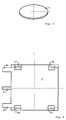
- Fig. 3 shows in perspective the conductive mat 3, which is designed as a thin, circular disc.
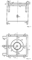
- Fig. 4 shows the limit switch from above.
- the four spring hooks 1j, 1k, 1q, 1r can be seen.
- the hooks press the circuit board 2 onto the underlying O-ring seal.
- Fig. 5 shows the view from the left.
- the resilient hooks 1j and 1q produced by deep cuts can be seen.
- Fig. 6 shows the limit switch from below.
- the stiffening webs 1o, 1p, 1v and 1w are arranged between the side walls 1a, 1b, 1c and 1u and the inner housing parts 1d, 1e and 1f, which give the housing optimum stability with the lowest weight.
- the novel acceleration limit switch shown is ideally suited to be used in all types of motor vehicles in order to activate airbags, belt tensioner systems and other elements in the vehicle which serve to provide safety.
Landscapes
- Physics & Mathematics (AREA)
- General Physics & Mathematics (AREA)
- Switch Cases, Indication, And Locking (AREA)
- Switches That Are Operated By Magnetic Or Electric Fields (AREA)
- Switches With Compound Operations (AREA)
- Switches Operated By Changes In Physical Conditions (AREA)
- Push-Button Switches (AREA)
- Jib Cranes (AREA)
- Vehicle Body Suspensions (AREA)
Abstract
Description
- Gegenstand der Erfindung ist ein Beschleunigungsgrenzwertschalter mit einem kugelförmigen Trägheitskörper aus ferromagnetischem Material, der von einem Dauermagneten in Ruhestellung gehalten ist, dem auf einer Leiterplatte zwei symmetrisch ineinandergreifende Kontaktelemente gegenüberstehen, wobei zwischen dem Trägheitskörper und der Leiterplatte eine elastische, leitfähige Membran befestigt ist, die beim Auftreffen des Trägheitskörpers verformt wird und dabei die Kontaktelemente verbindet.
- Aus dem deutschen Patent DE 30 22 878 ist ein Beschleunigungsgrenzwertschalter bekannt geworden, der aus einem Gehäuse mit Dauermagnet, einem von diesem Magneten gehaltenen Trägheitskörper und einem Kontaktsystem besteht. Dieses System weist eine leitfähige Membran und eine Leiterplatte mit kammartig ineinandergreifenden Leiterbahnen auf.
Die Leiterplatte und die Membran werden von einem übergreifenden Deckel gehalten, der Bohrungen zur Durchführung der Anschlußstifte aufweist.
Das zylindrische Gehäuse zeigt im Mantelbereich eine umlaufende Nut, in die ein O-Ring eingesetzt ist. Beim Aufschieben des Deckels dichtet sein Kragen unter Verformung des O-Ringes den Innenraum des Schalters ab.
Der bekannte und seit vielen Jahren erfolgreich eingesetzte Schalter benötigt außer einer geformten und damit teuren Kontaktmembran eine Leiterplatte mit eingelöteten Stiften sowie einen mit Kragen versehenen Deckel. Die Art der Abdichtung erfordert sehr kleine Toleranzen für Gehäuse und Deckel. - Der Erfindung liegt die Aufgabe zugrunde, den bekannten Schalter ohne Einbußen an Zuverlässigkeit und Ansprechgenauigkeit entscheidend zu vereinfachen und zu verbilligen.
- Dies gelingt gemäß der Erfindung dadurch, daß der rotationssymmetrische Innenraum des Schalters eine ringförmige Lagerfläche für eine dünne Leitkunststoff-Matte aufweist, daß die Leiterplatte als Gehäusedeckel auf einem umlaufenden Gehäusesteg aufliegt, daß außerhalb dieses Steges ein Dichtungsring liegt und daß die Leiterplatte unter Deformation des Dichtungsringes von gehäuseseitig angeformten, federnden Haken gehalten ist.
- Ein Ausführungsbeispiel der Erfindung wird anhand von Fig. 1 - 6 der Zeichnung beschrieben.
- Fig. 1
- zeigt einen Längsschnitt durch den Beschleunigungsgrenzwertschalter,
- Fig. 2
- die Leiterplatte,
- Fig. 3
- die Leitkunststoff-Matte,
- Fig. 4
- die Ansicht von oben,
- Fig. 5
- die Ansicht von links,
- Fig. 6
- die Ansicht von unten.
- In Fig. 1 ist mit 1 das im Längsschnitt dargestellte Gehäuse bezeichnet, das weitgehend als Hohlkörper ausgebildet ist. Das im Spritzgußverfahren aus Kunststoff hergestellte quaderförmige Gehäuse besteht im wesentlichen aus vier relativ dünnen Seitenwänden. Teilweise sichtbar ist die Rückwand 1a. Ferner erkennt man die im Schnitt dargestellten Seitenwände 1b und 1c. Für die Funktion wichtig ist das Innengehäuse, das aus einem hohlzylindrischen Abschnitt 1d, einem hohlkegelförmigen Abschnitt 1e und einem hohlzylindrischen Abschnitt 1f besteht. Nach oben hin verbindet ein Flansch 1g das Innen- und Außengehäuse. Dieser Flansch geht in einen ringförmigen Steg 1h über, auf dem eine Leiterplatte 2 aufliegt. Innerhalb des Steges liegt eine dünne, kreisrunde Leitkunststoff-Matte 3. Außen um den Steg 1h herum ist ein Dichtungs-O-Ring 4 gelagert. Die Leiterplatte 2 stellt zugleich den Deckel des Gehäuses dar. Die Leiterplatte 2 preßt den O-Ring 4 dichtend zusammen und wird in dieser Lage durch federnde Haken 1j, 1k gehalten. Diese Haken - insgesamt 4 an allen Ecken - sind aus dem Gehäuse herausgeformt.
In den Teil 1d des inneren Gehäuses ist ein zylindrischer Dauermagnet 5 eingepreßt. In dem hohlkegeligen Abschnitt 1e ruht ein ferromagnetischer Trägheitskörper 6, der von dem Magneten 5 mit einer ganz bestimmten Kraft gehalten wird.
Wenn der Schalter einer über dem Grenzwert liegenden Beschleunigung ausgesetzt wird, löst sich der Trägheitskörper 6, eine Stahlkugel, von dem Magneten 5 und prallt gegen die leitfähige Matte 3. Diese Matte überbrückt kurzzeitig die Leiterbahnen, deren Anordnung aus der Draufsicht in Fig. 2 hervorgeht.
Auf der Leiterplatte 2 sind Leiterbahnen 2a und 2b vorgesehen, die sich im Zentrum 2c kammartig gegenüberstehen. Wenn die leitfähige Matte 3 auf das Zentrum 2c aufgepreßt wird, entstehen mehrere Teilkontakte, so daß eine sichere Signalgebung gewährleistet ist.
Die Leiterplatte 2 weist zwei Anschlußstreifen 2d und 2e auf, die in eine Trägerplatte eingelötet werden können.
Zum konstruktiven Aufbau des Gehäuses 1 ist noch nachzutragen, daß aus der linken Seitenwand 1b eine Lasche 1l heraustritt, so daß sich zusammen mit den Anschlußstreifen 2d und 2e eine Dreipunktbefestigung ergibt.
Zur alternativen Befestigung in einer um 90° versetzten Ebene sind Beine 1m und 1n an die Rückwand 1a angeformt. Zwei weitere Beine befinden sich an der nicht dargestellten Parallelwand.
Zwischen den Seitenwänden 1b, 1c und dem Innengehäuse 1d, 1e, 1f sind Versteifungsstege 1o und 1p eingeformt. Dadurch kommt das Gesamtgehäuse mit sehr dünnen Wänden aus. Dies hat den Vorteil, daß die Schrumpfung und der Verzug bei der Abkühlung des heißgespritzten Gehäuses gering bleibt.
Um die Leiterbahnen vor Oxyd- oder Sulfidschichten zu schützen, können sie im Lötbad oder galvanisch verzinnt werden. - In Fig. 2 ist dargestellt, daß die Leiterbahnen im Bereich 2c kammartig ineinandergreifen.
Die Kontaktelemente auf der Leiterplatte könnten aber auch sternförmig von innen nach außen und von außen nach innen ineinandergreifen, um das Ansprechen völlig richtungsunabhängig zu gestalten.
Aus dem Leiterbild nach Fig. 2 ist ferner ersichtlich, daß im Bereich der Auflagefläche des O-Ringes zwei Leiterbahnen 2f, 2g ringförmig parallel aneinander vorbeigeführt sind. Damit wird erreicht, daß der O-Ring im Bereich zwischen den erhabenen Leiterbahnen besonders gut abdichtet. - Fig. 3 zeigt in Perspektive die leitfähige Matte 3, die als dünne, kreisrunde Scheibe ausgebildet ist.
- Fig. 4 stellt den Grenzwertschalter von oben dar. Man erkennt die vier Federhaken 1j, 1k, 1q, 1r. Die Haken pressen die Leiterplatte 2 auf die darunterliegende O-Ring-Dichtung.
- Fig. 5 gibt die Ansicht von links wieder. Man erkennt die durch tiefe Einschnitte hergestellten federnden Haken 1j und 1q.
- Fig. 6 zeigt den Grenzwertschalter von unten. Zwischen den Seitenwänden 1a, 1b, 1c und 1u und den inneren Gehäuseteilen 1d, 1e und 1f sind die Versteifungsstege 1o, 1p, 1v und 1w angeordnet, die dem Gehäuse bei geringstem Gewicht eine optimale Stabilität verleihen.
- Der dargestellte, neuartige Beschleunigungsgrenzwertschalter ist hervorragend geeignet, in Kraftfahrzeugen jeder Art eingesetzt zu werden, um Airbags, Gurtstraffersysteme und andere, der Sicherheit dienende Elemente im Fahrzeug zu aktivieren.
-
- 1
- Gehäuse
- 1a
- Rückwand
- 1b, 1c
- Seitenwände
- 1d
- hohlzylindrischer Abschnitt
- 1e
- hohlkegeliger Abschnitt
- 1f
- hohlzylindrischer Abschnitt
- 1g
- Flansch
- 1g1
- Lagerfläche
- 1h
- ringförmiger Steg
- 1j, 1k
- federnde Haken
- 1l
- Lasche
- 1m, 1n
- Beine
- 1o, 1p
- Versteifungsstege
- 1g, 1r
- Federhaken
- 1s, 1t
- Füße
- 1u
- Seitenwand
- 1v, 1w
- Versteifungsstege
- 2
- Leiterplatte
- 2a, 2b
- Leiterbahnen
- 2c
- Zentrum
- 2d, 2e
- Anschlußstreifen
- 2f, 2g
- Leiterbahnen
- 3
- Leitkunststoff-Matte
- 4
- Dichtungs-O-Ring
- 5
- Dauermagnet
- 6
- Trägheitskörper
Claims (8)
- Beschleunigungsgrenzwertschalter mit einem kugelförmigen Trägheitskörper aus ferromagnetischem Material, der von einem Dauermagneten in Ruhestellung gehalten ist, dem auf einer Leiterplatte zwei symmetrisch ineinandergreifende Kontaktelemente gegenüberstehen, wobei zwischen dem Trägheitskörper und der Leiterplatte eine elastische, leitfähige Membran befestigt ist, die beim Auftreffen des Trägheitskörpers verformt wird und dabei die Kontaktelemente verbindet,
dadurch gekennzeichnet,
daß der rotationssymmetrische Innenraum des Schalters (1e, 1f) eine ringförmige Lagerfläche (1g1)für eine dünne Leitkunststoff-Matte (3) aufweist,
daß die Leiterplatte (2) als Gehäusedeckel auf einem umlaufenden Gehäusesteg (1h) aufliegt,
daß außerhalb dieses Steges (1h) ein Dichtungsring (4) liegt und
daß die Leiterplatte (2) unter Deformation des Dichtungsringes (4) von gehäuseseitig angeformten, federnden Haken (1j, 1k) gehalten ist. - Beschleunigungsgrenzwertschalter nach Anspruch 1, dadurch gekennzeichnet, daß die Leiterplatte zwei angeformte Anschlußstreifen (2d, 2e) aufweist und daß die Leiterbahnen (2a, 2b, 2c) verzinnt sind.
- Beschleunigungsgrenzwertschalter nach Anspruch 1, dadurch gekennzeichnet, daß das gesamte Gehäuse (1) einschließlich der federnden Haken (1j, 1k) aus einem formbeständigen, elastischen Kunststoff gespritzt ist.
- Beschleunigungsgrenzwertschalter nach Anspruch 1, dadurch gekennzeichnet, daß das quaderförmige Gehäuse (1) weitgehend hohl gestaltet ist, indem es lediglich aus vier dünnen Seitenwänden (1a, 1b, 1c), dem oberen Verbindungsflansch (1g) und dem sich daran anschließenden trichterförmigen Innengehäuse (1d, 1e, 1f) zur Aufnahme des Dauermagneten (5) und des Trägheitskörpers (6) besteht.
- Beschleunigungsgrenzwertschalter nach Anspruch 4, dadurch gekennzeichnet, daß zwischen den Seitenwänden (1b, 1c) und dem trichterförmigen Innengehäuse (1e, 1f) Versteifungsstege (1o, 1p) angeordnet sind.
- Beschleunigungsgrenzwertschalter nach Anspruch 1, dadurch gekennzeichnet, daß das Magnetsystem lediglich aus einem eingepreßten, zylindrischen Dauermagneten (5) ohne Rückschlußkörper besteht.
- Beschleunigungsgrenzwertschalter nach Anspruch 1, dadurch gekennzeichnet, daß die Kontaktelemente der Leiterplatte (2) sternförmig ineinandergreifen, um das Ansprechen richtungsunabhängig zu gestalten.
- Beschleunigungsgrenzwertschalter nach Anspruch 1, dadurch gekennzeichnet, daß im Bereich der Auflagefläche des O-Ringes (4) zwei erhabene Leiterbahnen (2f, 2g) ringförmig parallel angeordnet sind, um die Abdichtung zu verbessern.
Applications Claiming Priority (2)
| Application Number | Priority Date | Filing Date | Title |
|---|---|---|---|
| DE4434349A DE4434349A1 (de) | 1994-09-26 | 1994-09-26 | Beschleunigungsgrenzwertschalter |
| DE4434349 | 1994-09-26 |
Publications (2)
| Publication Number | Publication Date |
|---|---|
| EP0708467A1 true EP0708467A1 (de) | 1996-04-24 |
| EP0708467B1 EP0708467B1 (de) | 1999-01-13 |
Family
ID=6529208
Family Applications (1)
| Application Number | Title | Priority Date | Filing Date |
|---|---|---|---|
| EP95114278A Expired - Lifetime EP0708467B1 (de) | 1994-09-26 | 1995-09-12 | Beschleunigungsgrenzwertschalter |
Country Status (5)
| Country | Link |
|---|---|
| US (1) | US5597066A (de) |
| EP (1) | EP0708467B1 (de) |
| AT (1) | ATE175810T1 (de) |
| DE (2) | DE4434349A1 (de) |
| ES (1) | ES2126823T3 (de) |
Cited By (9)
| Publication number | Priority date | Publication date | Assignee | Title |
|---|---|---|---|---|
| EP1164612A1 (de) * | 2000-06-13 | 2001-12-19 | Helbako Elektronik-Baugruppen GmbH & Co.KG | Beschleunigungsgrenzwertschalter |
| RU2520596C2 (ru) * | 2012-05-24 | 2014-06-27 | Федеральное государственное унитарное предприятие "Российский федеральный ядерный центр-Всероссийский научно-исследовательский институт технической физики имени академика Е.И. Забабахина" | Инерционный включатель |
| RU2521000C2 (ru) * | 2012-07-27 | 2014-06-27 | Федеральное государственное унитарное предприятие "Российский федеральный ядерный центр-Всероссийский научно-исследовательский институт технической физики имени академика Е.И. Забабахина" | Инерционный включатель |
| RU2542336C2 (ru) * | 2013-07-09 | 2015-02-20 | Российская Федерация, от имени которой выступает Государственная корпорация по атомной энергии "Росатом" (Госкорпорация "Росатом") | Инерционный включатель |
| RU2562057C2 (ru) * | 2013-12-30 | 2015-09-10 | Российская Федерация, от имени которой выступает Государственная корпорация по атомной энергии "Росатом" (Госкорпорация "Росатом") | Инерционный включатель |
| RU2685543C1 (ru) * | 2018-06-06 | 2019-04-22 | Российская Федерация, от имени которой выступает Государственная корпорация по атомной энергии "Росатом" (Госкорпорация "Росатом") | Контактная система |
| RU2691740C1 (ru) * | 2018-10-25 | 2019-06-18 | Российская Федерация, от имени которой выступает Государственная корпорация по атомной энергии "Росатом" (Госкорпорация "Росатом") | Контактная система |
| RU2693836C1 (ru) * | 2018-09-06 | 2019-07-05 | Российская Федерация, от имени которой выступает Государственная корпорация по атомной энергии "Росатом" (Госкорпорация "Росатом") | Инерционный включатель |
| RU2700169C2 (ru) * | 2018-03-05 | 2019-09-13 | Российская Федерация, от имени которой выступает Государственная корпорация по атомной энергии "Росатом" (Госкорпорация "Росатом") | Инерционный включатель |
Families Citing this family (10)
| Publication number | Priority date | Publication date | Assignee | Title |
|---|---|---|---|---|
| JPH09167551A (ja) * | 1995-12-18 | 1997-06-24 | Jeco Co Ltd | 加速度スイッチ |
| US6305975B1 (en) * | 2000-10-12 | 2001-10-23 | Bear Instruments, Inc. | Electrical connector feedthrough to low pressure chamber |
| US6518523B1 (en) * | 2001-11-13 | 2003-02-11 | Tien-Ming Chou | Tilt switch |
| US7190278B2 (en) * | 2004-03-08 | 2007-03-13 | Nuvo Holdings, Llc | Asset tag with event detection capabilities |
| US7088258B2 (en) * | 2004-03-08 | 2006-08-08 | Nuvo Holdings, Llc | Tilt sensor apparatus and method therefor |
| US8387531B2 (en) * | 2007-02-28 | 2013-03-05 | Tessera, Inc. | Impact sensing switch |
| US20120325629A1 (en) * | 2011-06-22 | 2012-12-27 | Xiao-Feng Li | Tilt Switch |
| CN103065865A (zh) * | 2012-12-20 | 2013-04-24 | 李捷逵 | 一种用于无线终端的万向碰撞开关 |
| TWI564563B (zh) | 2015-03-11 | 2017-01-01 | Zhi- Huang | Multi-directional sensor |
| CN106158504A (zh) * | 2015-03-31 | 2016-11-23 | 黄志恒 | 多方向感测器 |
Citations (3)
| Publication number | Priority date | Publication date | Assignee | Title |
|---|---|---|---|---|
| DE3022878A1 (de) | 1980-06-19 | 1982-01-07 | Helba Elektronik-Baugruppen Gmbh & Co Kg, 5628 Heiligenhaus | Beschleunigungsgrenzwertschalter |
| DE8310623U1 (de) * | 1983-04-12 | 1983-09-08 | Helba Elektronik-Baugruppen Gmbh & Co Kg, 5628 Heiligenhaus | Beschleunigungsgrenzwertschalter |
| US5010217A (en) * | 1990-02-26 | 1991-04-23 | Siemens Automotive Limited | Inertia switch mounting housing |
Family Cites Families (4)
| Publication number | Priority date | Publication date | Assignee | Title |
|---|---|---|---|---|
| US5068502A (en) * | 1989-11-13 | 1991-11-26 | Siemens-Bendix Automotive Electronics Limited | Magnetically biased velocity change sensor |
| US5237134A (en) * | 1989-12-06 | 1993-08-17 | Breed Automotive Technology, Inc. | Gas damped crash sensor |
| US5053588A (en) * | 1990-02-20 | 1991-10-01 | Trw Technar Inc. | Calibratable crash sensor |
| IT1257226B (it) * | 1991-06-11 | 1996-01-10 | Breed Automotive Tech | Sensore del cambiamento di velocita' con un magnete cilindrico. |
-
1994
- 1994-09-26 DE DE4434349A patent/DE4434349A1/de not_active Withdrawn
-
1995
- 1995-09-12 DE DE59504795T patent/DE59504795D1/de not_active Expired - Lifetime
- 1995-09-12 AT AT95114278T patent/ATE175810T1/de not_active IP Right Cessation
- 1995-09-12 EP EP95114278A patent/EP0708467B1/de not_active Expired - Lifetime
- 1995-09-12 ES ES95114278T patent/ES2126823T3/es not_active Expired - Lifetime
- 1995-09-19 US US08/530,075 patent/US5597066A/en not_active Expired - Lifetime
Patent Citations (4)
| Publication number | Priority date | Publication date | Assignee | Title |
|---|---|---|---|---|
| DE3022878A1 (de) | 1980-06-19 | 1982-01-07 | Helba Elektronik-Baugruppen Gmbh & Co Kg, 5628 Heiligenhaus | Beschleunigungsgrenzwertschalter |
| DE8310623U1 (de) * | 1983-04-12 | 1983-09-08 | Helba Elektronik-Baugruppen Gmbh & Co Kg, 5628 Heiligenhaus | Beschleunigungsgrenzwertschalter |
| DE8401991U1 (de) * | 1983-04-12 | 1984-06-28 | Helba Elektronik-Baugruppen Gmbh & Co Kg, 5628 Heiligenhaus | Beschleunigungsgrenzwertschalter |
| US5010217A (en) * | 1990-02-26 | 1991-04-23 | Siemens Automotive Limited | Inertia switch mounting housing |
Cited By (9)
| Publication number | Priority date | Publication date | Assignee | Title |
|---|---|---|---|---|
| EP1164612A1 (de) * | 2000-06-13 | 2001-12-19 | Helbako Elektronik-Baugruppen GmbH & Co.KG | Beschleunigungsgrenzwertschalter |
| RU2520596C2 (ru) * | 2012-05-24 | 2014-06-27 | Федеральное государственное унитарное предприятие "Российский федеральный ядерный центр-Всероссийский научно-исследовательский институт технической физики имени академика Е.И. Забабахина" | Инерционный включатель |
| RU2521000C2 (ru) * | 2012-07-27 | 2014-06-27 | Федеральное государственное унитарное предприятие "Российский федеральный ядерный центр-Всероссийский научно-исследовательский институт технической физики имени академика Е.И. Забабахина" | Инерционный включатель |
| RU2542336C2 (ru) * | 2013-07-09 | 2015-02-20 | Российская Федерация, от имени которой выступает Государственная корпорация по атомной энергии "Росатом" (Госкорпорация "Росатом") | Инерционный включатель |
| RU2562057C2 (ru) * | 2013-12-30 | 2015-09-10 | Российская Федерация, от имени которой выступает Государственная корпорация по атомной энергии "Росатом" (Госкорпорация "Росатом") | Инерционный включатель |
| RU2700169C2 (ru) * | 2018-03-05 | 2019-09-13 | Российская Федерация, от имени которой выступает Государственная корпорация по атомной энергии "Росатом" (Госкорпорация "Росатом") | Инерционный включатель |
| RU2685543C1 (ru) * | 2018-06-06 | 2019-04-22 | Российская Федерация, от имени которой выступает Государственная корпорация по атомной энергии "Росатом" (Госкорпорация "Росатом") | Контактная система |
| RU2693836C1 (ru) * | 2018-09-06 | 2019-07-05 | Российская Федерация, от имени которой выступает Государственная корпорация по атомной энергии "Росатом" (Госкорпорация "Росатом") | Инерционный включатель |
| RU2691740C1 (ru) * | 2018-10-25 | 2019-06-18 | Российская Федерация, от имени которой выступает Государственная корпорация по атомной энергии "Росатом" (Госкорпорация "Росатом") | Контактная система |
Also Published As
| Publication number | Publication date |
|---|---|
| ATE175810T1 (de) | 1999-01-15 |
| US5597066A (en) | 1997-01-28 |
| DE4434349A1 (de) | 1996-03-28 |
| EP0708467B1 (de) | 1999-01-13 |
| ES2126823T3 (es) | 1999-04-01 |
| DE59504795D1 (de) | 1999-02-25 |
Similar Documents
| Publication | Publication Date | Title |
|---|---|---|
| EP0708467B1 (de) | Beschleunigungsgrenzwertschalter | |
| DE2341521C3 (de) | Drucktastenschalter | |
| EP0248940A1 (de) | Relais zur Betätigung eines Gurtstraffers an Kraftfahrzeug-Sicherheitshaltegurten | |
| DE8310623U1 (de) | Beschleunigungsgrenzwertschalter | |
| DE3820829C2 (de) | ||
| DE1615895A1 (de) | Traegheitsschalter | |
| DE3112328A1 (de) | Druckschalter mit einer kappenfoermigen drucktaste | |
| DE3883124T2 (de) | Elektrisches Massenkraftschalter. | |
| DE3313033C1 (de) | Beschleunigungsgrenzwertschalter | |
| DE4022388C2 (de) | ||
| DE60102092T2 (de) | Schaltereinheit für ein Lenkrad in einem Kraftfahrzeug | |
| DE9101018U1 (de) | Drucktastenschalter | |
| EP0311039A2 (de) | Schaltungsanordnung zum Erfassen von Beschleunigungen | |
| DE4142759A1 (de) | Beschleunigungssensor | |
| DE1944732C3 (de) | Elektrischer Trägheitsschalter | |
| DE8016137U1 (de) | Beschleunigungsgrenzwertschalter | |
| DE2333427C3 (de) | Beschleunigungsgrenzwertschalter, insbesondere zur Steuerung von Warnblinkanlagen in Kraftfahrzeugen | |
| DE2928328C2 (de) | Diebstahlsicherung für Fahrzeuge | |
| DE6933661U (de) | Vorrichtung zum befestigen eines geraetes, insbesondere eines schalters oder dergleichen im armaturenbrett eines kraftfahrzeuges. | |
| DE2232288A1 (de) | Pendelsensor | |
| DE69715859T2 (de) | Anordnung für ein fahrzeuglenkrad | |
| DE2257249A1 (de) | Belagabnutzungs-warneinrichtung | |
| DE69403944T2 (de) | Sicherheitsschalter | |
| DE2824210A1 (de) | Beschleunigungs- oder lagesensor | |
| CH660089A5 (en) | Miniature push-button switch and a method for its production |
Legal Events
| Date | Code | Title | Description |
|---|---|---|---|
| PUAI | Public reference made under article 153(3) epc to a published international application that has entered the european phase |
Free format text: ORIGINAL CODE: 0009012 |
|
| AK | Designated contracting states |
Kind code of ref document: A1 Designated state(s): AT BE CH DE DK ES FR GB IT LI LU NL PT SE |
|
| 17P | Request for examination filed |
Effective date: 19961019 |
|
| GRAG | Despatch of communication of intention to grant |
Free format text: ORIGINAL CODE: EPIDOS AGRA |
|
| GRAG | Despatch of communication of intention to grant |
Free format text: ORIGINAL CODE: EPIDOS AGRA |
|
| GRAH | Despatch of communication of intention to grant a patent |
Free format text: ORIGINAL CODE: EPIDOS IGRA |
|
| 17Q | First examination report despatched |
Effective date: 19980701 |
|
| GRAH | Despatch of communication of intention to grant a patent |
Free format text: ORIGINAL CODE: EPIDOS IGRA |
|
| GRAA | (expected) grant |
Free format text: ORIGINAL CODE: 0009210 |
|
| AK | Designated contracting states |
Kind code of ref document: B1 Designated state(s): AT BE CH DE DK ES FR GB IT LI LU NL PT SE |
|
| PG25 | Lapsed in a contracting state [announced via postgrant information from national office to epo] |
Ref country code: SE Free format text: THE PATENT HAS BEEN ANNULLED BY A DECISION OF A NATIONAL AUTHORITY Effective date: 19990113 Ref country code: NL Free format text: LAPSE BECAUSE OF FAILURE TO SUBMIT A TRANSLATION OF THE DESCRIPTION OR TO PAY THE FEE WITHIN THE PRESCRIBED TIME-LIMIT Effective date: 19990113 |
|
| REF | Corresponds to: |
Ref document number: 175810 Country of ref document: AT Date of ref document: 19990115 Kind code of ref document: T |
|
| REG | Reference to a national code |
Ref country code: CH Ref legal event code: EP |
|
| GBT | Gb: translation of ep patent filed (gb section 77(6)(a)/1977) |
Effective date: 19990113 |
|
| REF | Corresponds to: |
Ref document number: 59504795 Country of ref document: DE Date of ref document: 19990225 |
|
| ET | Fr: translation filed | ||
| REG | Reference to a national code |
Ref country code: ES Ref legal event code: FG2A Ref document number: 2126823 Country of ref document: ES Kind code of ref document: T3 |
|
| ITF | It: translation for a ep patent filed | ||
| PG25 | Lapsed in a contracting state [announced via postgrant information from national office to epo] |
Ref country code: DK Free format text: LAPSE BECAUSE OF FAILURE TO SUBMIT A TRANSLATION OF THE DESCRIPTION OR TO PAY THE FEE WITHIN THE PRESCRIBED TIME-LIMIT Effective date: 19990413 |
|
| REG | Reference to a national code |
Ref country code: PT Ref legal event code: SC4A Free format text: AVAILABILITY OF NATIONAL TRANSLATION Effective date: 19990120 |
|
| NLV1 | Nl: lapsed or annulled due to failure to fulfill the requirements of art. 29p and 29m of the patents act | ||
| PG25 | Lapsed in a contracting state [announced via postgrant information from national office to epo] |
Ref country code: LU Free format text: LAPSE BECAUSE OF NON-PAYMENT OF DUE FEES Effective date: 19990912 Ref country code: AT Free format text: LAPSE BECAUSE OF NON-PAYMENT OF DUE FEES Effective date: 19990912 |
|
| PG25 | Lapsed in a contracting state [announced via postgrant information from national office to epo] |
Ref country code: LI Free format text: LAPSE BECAUSE OF NON-PAYMENT OF DUE FEES Effective date: 19990930 Ref country code: CH Free format text: LAPSE BECAUSE OF NON-PAYMENT OF DUE FEES Effective date: 19990930 Ref country code: BE Free format text: LAPSE BECAUSE OF NON-PAYMENT OF DUE FEES Effective date: 19990930 |
|
| PLBE | No opposition filed within time limit |
Free format text: ORIGINAL CODE: 0009261 |
|
| STAA | Information on the status of an ep patent application or granted ep patent |
Free format text: STATUS: NO OPPOSITION FILED WITHIN TIME LIMIT |
|
| 26N | No opposition filed | ||
| BERE | Be: lapsed |
Owner name: BURMESTER HEINO Effective date: 19990930 |
|
| REG | Reference to a national code |
Ref country code: CH Ref legal event code: PL |
|
| REG | Reference to a national code |
Ref country code: GB Ref legal event code: IF02 |
|
| PGFP | Annual fee paid to national office [announced via postgrant information from national office to epo] |
Ref country code: GB Payment date: 20040908 Year of fee payment: 10 Ref country code: FR Payment date: 20040908 Year of fee payment: 10 |
|
| PGFP | Annual fee paid to national office [announced via postgrant information from national office to epo] |
Ref country code: PT Payment date: 20040913 Year of fee payment: 10 |
|
| PGFP | Annual fee paid to national office [announced via postgrant information from national office to epo] |
Ref country code: ES Payment date: 20040921 Year of fee payment: 10 |
|
| PG25 | Lapsed in a contracting state [announced via postgrant information from national office to epo] |
Ref country code: IT Free format text: LAPSE BECAUSE OF NON-PAYMENT OF DUE FEES;WARNING: LAPSES OF ITALIAN PATENTS WITH EFFECTIVE DATE BEFORE 2007 MAY HAVE OCCURRED AT ANY TIME BEFORE 2007. THE CORRECT EFFECTIVE DATE MAY BE DIFFERENT FROM THE ONE RECORDED. Effective date: 20050912 Ref country code: GB Free format text: LAPSE BECAUSE OF NON-PAYMENT OF DUE FEES Effective date: 20050912 |
|
| PG25 | Lapsed in a contracting state [announced via postgrant information from national office to epo] |
Ref country code: ES Free format text: LAPSE BECAUSE OF NON-PAYMENT OF DUE FEES Effective date: 20050913 |
|
| PG25 | Lapsed in a contracting state [announced via postgrant information from national office to epo] |
Ref country code: PT Free format text: LAPSE BECAUSE OF NON-PAYMENT OF DUE FEES Effective date: 20060313 |
|
| GBPC | Gb: european patent ceased through non-payment of renewal fee |
Effective date: 20050912 |
|
| PG25 | Lapsed in a contracting state [announced via postgrant information from national office to epo] |
Ref country code: FR Free format text: LAPSE BECAUSE OF NON-PAYMENT OF DUE FEES Effective date: 20060531 |
|
| REG | Reference to a national code |
Ref country code: PT Ref legal event code: MM4A Effective date: 20060313 |
|
| REG | Reference to a national code |
Ref country code: FR Ref legal event code: ST Effective date: 20060531 |
|
| REG | Reference to a national code |
Ref country code: ES Ref legal event code: FD2A Effective date: 20050913 |
|
| PGFP | Annual fee paid to national office [announced via postgrant information from national office to epo] |
Ref country code: DE Payment date: 20120927 Year of fee payment: 18 |
|
| REG | Reference to a national code |
Ref country code: DE Ref legal event code: R119 Ref document number: 59504795 Country of ref document: DE Effective date: 20140401 |
|
| PG25 | Lapsed in a contracting state [announced via postgrant information from national office to epo] |
Ref country code: DE Free format text: LAPSE BECAUSE OF NON-PAYMENT OF DUE FEES Effective date: 20140401 |