EP0708232A2 - Vorrichtung mit mindestens einer Drosselklappe - Google Patents
Vorrichtung mit mindestens einer Drosselklappe Download PDFInfo
- Publication number
- EP0708232A2 EP0708232A2 EP95115332A EP95115332A EP0708232A2 EP 0708232 A2 EP0708232 A2 EP 0708232A2 EP 95115332 A EP95115332 A EP 95115332A EP 95115332 A EP95115332 A EP 95115332A EP 0708232 A2 EP0708232 A2 EP 0708232A2
- Authority
- EP
- European Patent Office
- Prior art keywords
- throttle valve
- shaft
- sleeves
- connection point
- recess
- Prior art date
- Legal status (The legal status is an assumption and is not a legal conclusion. Google has not performed a legal analysis and makes no representation as to the accuracy of the status listed.)
- Granted
Links
Images
Classifications
-
- F—MECHANICAL ENGINEERING; LIGHTING; HEATING; WEAPONS; BLASTING
- F02—COMBUSTION ENGINES; HOT-GAS OR COMBUSTION-PRODUCT ENGINE PLANTS
- F02D—CONTROLLING COMBUSTION ENGINES
- F02D9/00—Controlling engines by throttling air or fuel-and-air induction conduits or exhaust conduits
- F02D9/08—Throttle valves specially adapted therefor; Arrangements of such valves in conduits
- F02D9/10—Throttle valves specially adapted therefor; Arrangements of such valves in conduits having pivotally-mounted flaps
- F02D9/109—Throttle valves specially adapted therefor; Arrangements of such valves in conduits having pivotally-mounted flaps having two or more flaps
- F02D9/1095—Rotating on a common axis, e.g. having a common shaft
-
- F—MECHANICAL ENGINEERING; LIGHTING; HEATING; WEAPONS; BLASTING
- F02—COMBUSTION ENGINES; HOT-GAS OR COMBUSTION-PRODUCT ENGINE PLANTS
- F02D—CONTROLLING COMBUSTION ENGINES
- F02D9/00—Controlling engines by throttling air or fuel-and-air induction conduits or exhaust conduits
- F02D9/08—Throttle valves specially adapted therefor; Arrangements of such valves in conduits
- F02D9/10—Throttle valves specially adapted therefor; Arrangements of such valves in conduits having pivotally-mounted flaps
- F02D9/1005—Details of the flap
- F02D9/101—Special flap shapes, ribs, bores or the like
Definitions
- the invention relates to a device with at least one throttle valve located within an intake bore, which is arranged on a shaft.
- Devices of this type are used, for example, in suction and dosing devices in internal combustion engines in order to feed the exhaust gases of the engine back to combustion.
- the supply of the exhaust gases is controlled by means of a plurality of throttle valves, the throttle valves being pivotable about 90 ° via the shaft. Screws are usually used to attach the throttle valves to the shaft. Such an attachment requires a considerable manufacturing effort.
- the object of the invention is therefore to provide an improved device of the type mentioned, in which the function of the throttle valve and the shaft is reliably maintained.
- the throttle valve In order to maintain the welded joint, the throttle valve is welded onto the shaft at at least one point. As a result, the throttle valve is sufficiently secured to the shaft and the considerable mechanical Manufacturing effort as in the prior art is eliminated. If the throttle valve is to be detached from the shaft again, this is done by a slap on the back of the throttle valve, which breaks the welded joint.
- a particularly preferred embodiment of the invention consists in that two welded connection points lying next to one another in the axial direction of the shaft are provided.
- these two welded joints can be arranged symmetrically to the center of the throttle valve and the edge of the throttle valve. This prevents the throttle valve from bending away from the shaft during intensive use.
- the throttle valve is always on one level and lies directly on the shaft.
- the welded connection points are expediently designed as laser welded connection points, which can be produced by means of a laser spot welding device.
- a further embodiment of the invention provides that a stamping is provided on the shaft and a recess in the throttle valve is provided for receiving the stamping.
- the recess is advantageously arranged in the middle of the throttle valve.
- the throttle valve In its maximum closed position, the throttle valve does not lie completely against the inner walls of the intake bore, but encloses an angle of 3 ° with a plane perpendicular to the intake bore.
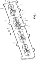
- the device according to the invention consists of a base body 1 with an upper side 2 and an underside 3. Eight continuous suction bores 4, each with an inlet 5 and an outlet 6, extend from the upper side 2 to the underside 3. All suction bores 4 extend radially and approximately in half the depth of the bores, a continuous shaft 7, which is mounted within the base body 1.
- a throttle valve 8 is fastened on the shaft 7 within four of the eight bores 4.
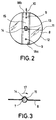
- two welded connection points 9 are provided between each throttle valve 8 and the shaft 7, which are arranged next to one another in the axial direction 10 of the shaft 7.
- the welded joints 9 are symmetrical to the center 11 of the throttle valve 8 and are arranged near an edge 12 of the throttle valve 8.
- the throttle valve 8 has a rectangular recess 13, symmetrical to its center 11, into which a rectangular shape 14 of the shaft 7 projects. By means of this characteristic 14, the throttle valve 8 can be fixed on the shaft 7 in the circumferential direction 17.
- the recess 13 is located in the region of a dome-shaped elevation 15 of the otherwise disk-shaped throttle valve 8.
- the elevation 15 extends radially over the throttle valve and has such a curvature that it bears on the shaft 7 when the throttle valve 8 is fitted.
- sleeves 16a and 16b provided, which are located within the base body 1 and are flush with the inner walls of the suction bores 4. The sleeves serve to support the shaft within the base body 1.
- the throttle valve 8 is arranged between two of these sleeves 16, they can also serve as a stop for the edge 12 of the throttle valve 8.
- the distance dimensions between two sleeves 16a and 16b are chosen so that they correspond to those between the two flattened end edge surfaces 18a and 18b of a throttle valve 8, so that the throttle valve is axially fixed in the direction of arrow 10 in FIG. 2 by the interaction of sleeves and end edge surfaces the wave occurs.
- the plane of the throttle valve 8 lies in a plane which is spanned by the axis of the shaft 7 and the central axis of the intake bore 4.
- the throttle valve 8 lies in a plane which is inclined by 3 ° with respect to a plane spanned by the axial direction 10 of the shaft 7 and a radial central axis of the bore 4.
- the edge 12 of the throttle valve 8 does not lie completely against the inner wall of the bore 4, but the throttle valve is located somewhat above and below the shaft 7, as seen from the shaft 7.
- the throttle valve 8 is attached to the shaft 7, the throttle valve 8 is first placed on the shaft 7 in such a way that the shape 14 engages in the recess 13, the dome-shaped elevation 15 abutting the shaft 7. This allows the throttle valve 8 to be fixed in the circumferential direction 17. In the axial direction, it is fixed by the interaction of the end edge surfaces and the sleeves. The throttle valve 8 is then spot-welded onto the shaft 7 at two points using a laser spot welding device in order to produce the welded connection points 9. Thus, the throttle valve 8 is attached to the shaft 7 in a simple manner. Through the suction holes 4, gases can then be sucked through, the degree of passage being determined by the position of the throttle valve 8, which is actuated by the shaft 7.
Landscapes
- Engineering & Computer Science (AREA)
- Chemical & Material Sciences (AREA)
- Combustion & Propulsion (AREA)
- Mechanical Engineering (AREA)
- General Engineering & Computer Science (AREA)
- Control Of Throttle Valves Provided In The Intake System Or In The Exhaust System (AREA)
- Laser Beam Processing (AREA)
- Lift Valve (AREA)
Abstract
Description
- Die Erfindung bezieht sich auf eine Vorrichtung mit mindestens einer innerhalb einer Ansaugbohrung befindlichen Drosselklappe, welche auf einer Welle angeordnet ist.
- Derartige Vorrichtungen werden beispielsweise in Saug- und Dossiervorrichtungen in Verbrennungsmotoren verwendet, um die Abgase des Motors erneut einer Verbrennung zuzuführen. Mittels mehrerer Drosselklappen wird die Zuführung der Abgase gesteuert, wobei die Drosselklappen über die Welle um etwa 90° verschwenkbar sind. Zur Befestigung der Drosselklappen auf der Welle werden üblicherweise Schrauben verwendet. Eine derartige Befestigung erfordert einen erheblichen Fertigungsaufwand.
- Weiterhin ist es bekannt, die Drosselklappe mittels einer Clip-Klemm-Verbindung auf die Welle aufzubringen. Eine derartige Clipbefestigung hat den Nachteil eines aufwendigen Fertigungsverfahrens und birgt die Gefahr in sich, daß sich die Klappe bei Schwingungen lösen könnte.
- Die Aufgabe der Erfindung besteht somit darin, eine verbesserte Vorrichtung der eingangs genannten Art zu schaffen, bei der die Funktion der Drosselklappe und der Welle zuverlässig erhalten bleibt.
- Diese Aufgabe wird bei der eingangs genannten Vorrichtung erfindungsgemäß dadurch gelöst, daß zwischen der Drosselklappe und der Welle mindestens eine Schweißverbindungsstelle ausgebildet ist.
- Um die Schweißverbindungsstelle zu erhalten, wird die Drosselklappe mindestens an einer Stelle auf die Welle aufgeschweißt. Hierdurch ist die Drosselklappe in ausreichender Weise an der Welle gesichert und der erhebliche mechanische Herstellungsaufwand wie beim Stand der Technik entfällt. Soll die Drosselklappe wieder von der Welle gelöst werden, so erfolgt dies durch einen Schlag auf die Rückseite der Drosselklappe, wodurch die Schweißverbindungsstelle aufgebrochen wird.
- Um die Drosselklappe zusätzlich auf der Welle zu sichern, besteht eine besonders bevorzugte Ausführungsform der Erfindung darin, daß zwei in axialer Richtung der Welle nebeneinanderliegende Schweißverbindungsstellen vorgesehen sind. Vorteilhafterweise können diese beiden Schweißverbindungsstellen symmetrisch zur Mitte der Drosselklappe und dem Rand der Drosselklappe naheliegend angeordnet sein. Hierdurch wird verhindert, daß sich die Drosselklappe im Verlauf intensiver Benutzung von der Welle wegbiegen kann. Die Drosselklappe befindet sich immer in einer Ebene und liegt direkt auf der Welle auf.
- Zur leichten Fertigung sind die Schweißverbindungsstellen zweckmäßigerweise als Laserschweißverbindungsstellen ausgebildet, welche mittels eines Laserpunktschweißgerätes erzeugt werden können.
- Um die Drosselklappe auf der Welle vor der Ausbildung der Schweißverbindungsstelle in Umfangsrichtung der Welle zu fixieren, sieht eine weitere Ausführungsform der Erfindung vor, daß auf der Welle eine Ausprägung und in der Drosselklappe eine Ausnehmung zur Aufnahme der Ausprägung vorgesehen sind. Vorteilhafterweise ist die Ausnehmung in der Mitte der Drosselklappe angeordnet.
- In ihrer maximalen Schließstellung liegt die Drosselklappe nicht vollständig an den Innenwänden der Ansaugbohrung an, sondern schließt mit einer Ebene senkrecht zu der Ansaugbohrung einen Winkel von 3° ein.
- Die Erfindung wird nachstehend anhand der Zeichnung näher erläutert. Die Zeichnung zeigt ein Ausführungsbeispiel der Erfindung. Hierbei stellen dar:
- Fig. 1
- eine schematische Ansicht der erfindungsgemäßen Vorrichtung,
- Fig. 2
- eine Draufsicht auf eine Drosselklappe mit abgeschnittener Welle und
- Fig. 3
- einen Querschnitt nach Fig. 2.
- Die erfindungsgemäße Vorrichtung besteht aus einem Grundkörper 1 mit einer Oberseite 2 und einer Unterseite 3. Von der Oberseite 2 zur Unterseite 3 erstrecken sich acht durchgehende Ansaugbohrungen 4 mit jeweils einem Einlaß 5 und einem Auslaß 6. Durch alle Ansaugbohrungen 4 erstreckt sich radial und etwa in halber Tiefe der Bohrungen eine durchgehende Welle 7, welche innerhalb des Grundkörpers 1 gelagert ist. Innerhalb von vier der acht Bohrungen 4 ist auf der Welle 7 eine Drosselklappe 8 befestigt. Zur Befestigung sind zwischen jeder Drosselklappe 8 und der Welle 7 zwei Schweißverbindungsstellen 9 vorgesehen, welche in axialer Richtung 10 der Welle 7 nebeneinanderliegend angeordnet sind. Die Schweißverbindungsstellen 9 liegen symmetrisch zur Mitte 11 der Drosselklappe 8 und sind einem Rand 12 der Drosselklappe 8 naheliegend angeordnet. Symmetrisch zu ihrer Mitte 11 weist die Drosselklappe 8 eine rechteckige Ausnehmung 13 auf, in welche eine rechteckige Ausprägung 14 der Welle 7 hineinragt. Mittels dieser Ausprägung 14 kann die Drosselklappe 8 auf der Welle 7 in Umfangsrichtung 17 fixiert werden. Die Ausnehmung 13 befindet sich im Bereich einer kuppenförmigen Erhebung 15 der ansonsten scheibenförmigen Drosselklappe 8. Die Erhebung 15 erstreckt sich radial über die Drosselklappe und weist eine derartige Krümmung auf, daß sie auf der Welle 7 beim Aufsetzen der Drosselklappe 8 anliegt. Auf der Welle 7 sind weiterhin ortsfeste Hülsen 16a bzw. 16b vorgesehen, welche sich innerhalb des Grundkörpers 1 befinden und bündig mit den Innenwandungen der Ansaugbohrungen 4 abschließen. Die Hülsen dienen zur Lagerung der Welle innerhalb des Grundkörpers 1. Da die Drosselklappe 8 zwischen je zwei dieser Hülsen 16 angeordnet ist, können diese auch als Anschlag für den Rand 12 der Drosselklappe 8 dienen. Die Abstandsmaße zwischen zwei Hülsen 16a und 16b sind so gewählt, daß sie denen zwischen den beiden abgeflachten Stirnkantenflächen 18a und 18b einer Drosselklappe 8 entsprechen, so daß durch das Zuammenwirken von Hülsen und Stirnkantenflächen eine axiale Festlegung der Drosselklappe in Pfeilrichtung 10 der Fig. 2 auf der Welle erfolgt.
- In ihrer Offenstellung liegt die Ebene der Drosselklappe 8 in einer Ebene, welche von der Achse der Welle 7 und der Mittelachse der Ansaugbohrung 4 aufgespannt wird. In ihrer maximalen Schließstellung liegt die Drosselklappe 8 in einer Ebene, welche um 3° gegenüber einer Ebene geneigt ist, die von der axialen Richtung 10 der Welle 7 und einer radialen Mittelachse der Bohrung 4 aufgespannt wird. In dieser maximalen Schließstellung liegt der Rand 12 der Drosselklappe 8 nicht vollständig an der Innenwandung der Bohrung 4 an, sondern die Drosselklappe befindet sich von der Welle 7 aus gesehen etwas oberhalb und unterhalb der Welle 7.
- Wenn die Drosselklappe 8 auf der Welle 7 befestigt wird, so wird zuerst die Drosselklappe 8 auf die Welle 7 aufgesetzt und zwar derart, daß die Ausprägung 14 in die Ausnehmung 13 eingreift, wobei sich die kuppenförmige Erhebung 15 an die Welle 7 anlegt. Dies gestattet eine Fixierung der Drosselklappe 8 in Umfangsrichtung 17. In axialer Richtung erfolgt die Festlegung durch das Zusammenwirken von den Stirnkantenflächen und den Hülsen. Anschließend wird die Drosselklappe 8 an zwei Stellen auf die Welle 7 mit einem Laserpunktschweißgerät punktgeschweißt, um die Schweißverbindungsstellen 9 herzustellen. Somit ist die Drosselklappe 8 in einfacher Weise auf der Welle 7 befestigt. Durch die Ansaugbohrungen 4 können dann Gase hindurchgesaugt werden, wobei der Grad des Durchlasses durch die Stellung der Drosselklappe 8, welche über die Welle 7 betätigt wird, festgelegt ist.
Claims (8)
- Vorrichtung mit mindestens einer innerhalb einer Ansaugbohrung (4) befindlichen Drosselklappe (8), welche auf einer Welle (7) angeordnet ist, dadurch gekennzeichnet, daß zwischen der Drosselklappe (8) und der Welle (7) mindestens eine Schweißverbindungsstelle (9) ausgebildet ist.
- Vorrichtung nach Anspruch 1, dadurch gekennzeichnet, daß zwei in axialer Richtung (10) der Welle (7) nebeneinanderliegende Schweißverbindungsstellen (9) vorgesehen sind.
- Vorrichtung nach Anspruch 1 oder 2, dadurch gekennzeichnet, daß das oder die Schweißverbindungsstellen (9) symmetrisch zu einer Mitte (11) der Drosselklappe (8) angeordnet sind.
- Vorrichtung nach einem der vorhergehenden Ansprüche, dadurch gekennzeichnet, daß das oder die Schweißverbindungsstellen (9) als Laserschweißverbindungsstellen ausgebildet sind.
- Vorrichtung nach einem der vorhergehenden Ansprüche, dadurch gekennzeichnet, daß auf der Welle (7) eine Ausprägung (14) zur Fixierung der Drosselklappe (8) in Umfangsrichtung und in der Drosselklappe (8) eine Ausnehmung (13) zur Aufnahme der Ausprägung (14) vorgesehen sind.
- Vorrichtung nach Anspruch 5, dadurch gekennzeichnet, daß die Ausnehmung (13) in der Mitte (11) der Drosselklappe (8) angeordnet ist.
- Vorrichtung nach einem der vorhergehenden Ansprüche, dadurch gekennzeichnet, daß auf der Welle (7) ortsfeste Hülsen (16) vorgesehen sind, wobei die Drosselklappe (8) zwischen je zwei dieser Hülsen (16) angeordnet ist.
- Vorrichtung nach einem der vorhergehenden Ansprüche, dadurch gekennzeichnet, daß die Drosselklappe (8) eine maximale Schließstellung von 3° aufweist, wobei die Drosselklappe (8) mit einer Ebene senkrecht zu der Ansaugbohrung (4) den Winkel von 3° einschließt.
Applications Claiming Priority (2)
| Application Number | Priority Date | Filing Date | Title |
|---|---|---|---|
| DE9416842U DE9416842U1 (de) | 1994-10-19 | 1994-10-19 | Vorrichtung mit mindestens einer Drosselklappe |
| DE9416842U | 1994-10-19 |
Publications (3)
| Publication Number | Publication Date |
|---|---|
| EP0708232A2 true EP0708232A2 (de) | 1996-04-24 |
| EP0708232A3 EP0708232A3 (de) | 1996-05-29 |
| EP0708232B1 EP0708232B1 (de) | 1998-02-25 |
Family
ID=6915091
Family Applications (1)
| Application Number | Title | Priority Date | Filing Date |
|---|---|---|---|
| EP95115332A Revoked EP0708232B1 (de) | 1994-10-19 | 1995-09-28 | Vorrichtung mit mindestens einer Drosselklappe und Verfahren zum Herstellen dieser Vorrichtung |
Country Status (4)
| Country | Link |
|---|---|
| EP (1) | EP0708232B1 (de) |
| AT (1) | ATE163460T1 (de) |
| DE (2) | DE9416842U1 (de) |
| ES (1) | ES2113146T3 (de) |
Cited By (6)
| Publication number | Priority date | Publication date | Assignee | Title |
|---|---|---|---|---|
| EP0861977A3 (de) * | 1997-02-26 | 1999-04-28 | Knecht Filterwerke Gmbh | Drosselklappen-Einrichtung für eine Saugrohranlage eines Verbrennungsmotors |
| DE10055397A1 (de) * | 2000-11-09 | 2002-05-29 | Albert Handtmann Metallguswerk | Vorrichtung mit mindestens einer Drosselklappe und Verfahren zum Herstellen dieser Vorrichtung |
| DE10140410A1 (de) * | 2001-08-23 | 2003-03-13 | Siemens Ag | Drosselklappenanordnung |
| EP1231370A3 (de) * | 2001-02-07 | 2003-12-10 | Delphi Technologies, Inc. | Laserverschweisstes Luftsteuerventil und methode |
| FR2883620A1 (fr) * | 2005-03-24 | 2006-09-29 | Mark Iv Systemes Moteurs Sa | Dispositif de regulation a clapet, piece multicanaux comportant de tels dispositifs et procede de realisation |
| WO2013102562A1 (de) * | 2012-01-03 | 2013-07-11 | Continental Automotive Gmbh | Ventilvorrichtung für ein kraftfahrzeug |
Families Citing this family (2)
| Publication number | Priority date | Publication date | Assignee | Title |
|---|---|---|---|---|
| DE9416842U1 (de) * | 1994-10-19 | 1994-12-15 | Albert Handtmann Metallgußwerk GmbH & Co. KG, 88400 Biberach | Vorrichtung mit mindestens einer Drosselklappe |
| GB0501428D0 (en) * | 2005-01-22 | 2005-03-02 | Ricardo Consulting Eng | A split carburettor with an improved throttle butterfly |
Family Cites Families (19)
| Publication number | Priority date | Publication date | Assignee | Title |
|---|---|---|---|---|
| DE1600880A1 (de) * | 1951-01-28 | 1971-09-16 | Pierburg Kg A | Drosselklappe |
| DE1009448B (de) * | 1952-10-14 | 1957-05-29 | Gen Motors Corp | Zapfenloses Drehklappenventil |
| FR1604534A (de) * | 1967-07-12 | 1971-11-29 | ||
| GB1268044A (en) * | 1968-05-29 | 1972-03-22 | British Oxygen Co Ltd | Fusion of workpieces |
| CA852063A (en) * | 1968-12-11 | 1970-09-22 | Canadian Westinghouse Company Limited | Modified butterfly trip valve |
| US3929314A (en) * | 1973-06-08 | 1975-12-30 | Eaton Corp | Actuating means for a butterfly valve |
| FR2238878A1 (en) * | 1973-07-25 | 1975-02-21 | Ducroux Roger | Butterfly valve with O-ring around the flap - stub spindles make small angle with plane of the flap |
| DE2836141A1 (de) * | 1978-08-18 | 1980-02-28 | Schmitz & Schulte | Klappenscheibe von klappenventilen |
| GB2087516A (en) * | 1980-11-15 | 1982-05-26 | British Steam Specialties The | Butterfly valve |
| DE3150999C2 (de) * | 1981-12-23 | 1985-06-20 | Klöckner-Humboldt-Deutz AG, 5000 Köln | Naß-Setzmaschine zur Aufbereitung von Kohle oder sonstigen Mineralien |
| DE3217685A1 (de) * | 1982-05-11 | 1985-02-14 | Rische, Bernward, 8039 Puchheim | Waermeverschlussklappe typ back-o-spar zur energieeinsparung (oel und gas) durch waermebalance und neuentwickelter waermeentkopplung |
| JPH0672560B2 (ja) * | 1988-09-12 | 1994-09-14 | 三菱電機株式会社 | エンジンの吸気量調整装置 |
| FR2653198B1 (fr) * | 1989-10-16 | 1992-02-07 | Peugeot | Vanne a papillon perfectionnee. |
| FR2692622B1 (fr) * | 1992-06-17 | 1994-09-16 | Solex | Organe d'étranglement rotatif pour installation d'alimentation de moteur à combustion interne et corps de papillon en comportant application. |
| DE4221449A1 (de) * | 1992-06-30 | 1994-01-05 | Pierburg Gmbh | Anordnung einer Drosselklappe |
| DE4223724A1 (de) * | 1992-07-18 | 1994-01-20 | Bosch Gmbh Robert | Drosselvorrichtung für eine Brennkraftmaschine |
| DE4223933A1 (de) * | 1992-07-21 | 1994-01-27 | Bosch Gmbh Robert | Drosselvorrichtung für eine Brennkraftmaschine |
| DE9406803U1 (de) * | 1994-04-22 | 1994-08-04 | Hüttenberger Produktionstechnik Metallverarbeitung Martin GmbH & Co. KG, 35428 Langgöns | Auf einer Welle angeordnete Drosselklappe |
| DE9416842U1 (de) * | 1994-10-19 | 1994-12-15 | Albert Handtmann Metallgußwerk GmbH & Co. KG, 88400 Biberach | Vorrichtung mit mindestens einer Drosselklappe |
-
1994
- 1994-10-19 DE DE9416842U patent/DE9416842U1/de not_active Expired - Lifetime
-
1995
- 1995-09-28 DE DE59501486T patent/DE59501486D1/de not_active Revoked
- 1995-09-28 ES ES95115332T patent/ES2113146T3/es not_active Expired - Lifetime
- 1995-09-28 AT AT95115332T patent/ATE163460T1/de not_active IP Right Cessation
- 1995-09-28 EP EP95115332A patent/EP0708232B1/de not_active Revoked
Non-Patent Citations (1)
| Title |
|---|
| None |
Cited By (10)
| Publication number | Priority date | Publication date | Assignee | Title |
|---|---|---|---|---|
| EP0861977A3 (de) * | 1997-02-26 | 1999-04-28 | Knecht Filterwerke Gmbh | Drosselklappen-Einrichtung für eine Saugrohranlage eines Verbrennungsmotors |
| DE10055397A1 (de) * | 2000-11-09 | 2002-05-29 | Albert Handtmann Metallguswerk | Vorrichtung mit mindestens einer Drosselklappe und Verfahren zum Herstellen dieser Vorrichtung |
| EP1231370A3 (de) * | 2001-02-07 | 2003-12-10 | Delphi Technologies, Inc. | Laserverschweisstes Luftsteuerventil und methode |
| DE10140410A1 (de) * | 2001-08-23 | 2003-03-13 | Siemens Ag | Drosselklappenanordnung |
| FR2883620A1 (fr) * | 2005-03-24 | 2006-09-29 | Mark Iv Systemes Moteurs Sa | Dispositif de regulation a clapet, piece multicanaux comportant de tels dispositifs et procede de realisation |
| EP1707780A1 (de) * | 2005-03-24 | 2006-10-04 | Mark Iv Systemes Moteurs (Sas) | Drosselklapperegelvorrichtung, Mehrwegeteil mit solchen Vorrichtungen und Herstellungsverfahren |
| WO2013102562A1 (de) * | 2012-01-03 | 2013-07-11 | Continental Automotive Gmbh | Ventilvorrichtung für ein kraftfahrzeug |
| CN104024604A (zh) * | 2012-01-03 | 2014-09-03 | 大陆汽车有限责任公司 | 用于机动车的阀装置 |
| KR20140108654A (ko) * | 2012-01-03 | 2014-09-12 | 콘티넨탈 오토모티브 게엠베하 | 자동차용 밸브 장치 |
| US10358986B2 (en) | 2012-01-03 | 2019-07-23 | Continental Automotive Gmbh | Valve device for a motor vehicle |
Also Published As
| Publication number | Publication date |
|---|---|
| ATE163460T1 (de) | 1998-03-15 |
| DE9416842U1 (de) | 1994-12-15 |
| EP0708232B1 (de) | 1998-02-25 |
| EP0708232A3 (de) | 1996-05-29 |
| DE59501486D1 (de) | 1998-04-02 |
| ES2113146T3 (es) | 1998-04-16 |
Similar Documents
| Publication | Publication Date | Title |
|---|---|---|
| DE19537784B4 (de) | Montage einer sich selbst ausrichtenden verstellbaren Leitschaufel | |
| DE69000296T2 (de) | Verstellvorrichtung fuer schwenkbare leitschaufeln mit eingebautem drehteller. | |
| DE2811724A1 (de) | Zentrifugalverdichter und verdichtergehaeuse | |
| DE10311205B3 (de) | Leitapparat für eine Radialturbine | |
| EP3315728A1 (de) | Gedämpfte leitschaufellagerung | |
| EP0708232A2 (de) | Vorrichtung mit mindestens einer Drosselklappe | |
| EP0503424B1 (de) | Mit einer Riemenscheibe verbundener Drehschwingungsdämpfer | |
| DE19511479C2 (de) | Verbindungsvorrichtung | |
| DE2527633C3 (de) | Vorrichtung zur Feinzerstäubung eines Brennstoff-Luft-Gemisches in einer in den Einlaß einer Brennkraftmaschine führenden Leitung | |
| DE1601625A1 (de) | Schaufelbetaetigungsmechanismus,insbesondere fuer Leitradschaufeln in Gasturbinenstrahltriebwerken | |
| EP0075659A2 (de) | Hubkolbenbrennkraftmaschine, vorzugsweise vierzylindriger Bauart | |
| EP1186781A1 (de) | Befestigungsvorrichtung für einen Filterschalldämpfer am Verdichtereingang eines Turboladers | |
| DE19752044B4 (de) | Vorrichtung zur Befestigung eines Deckels an einem Motorgehäuse eines motorgetriebenen Werkzeuges | |
| EP0318457A1 (de) | Anordnung zur Befestigung der Abgasanlage am Abgassammler einer Brennkraftmaschine | |
| DE60317119T2 (de) | Steuereinrichtung für Statorschaufel | |
| DE60215327T2 (de) | Turbinen- oder kompressorvorrichtung und verfahren zur montage der vorrichtung | |
| DE19544188C2 (de) | Hydrodynamischer Retarder oder hydrodynamische Kupplung | |
| DE69812053T2 (de) | Überwanne zur Ölwanne und Brennkraftmaschine mit dieser Überwanne | |
| DE69502511T2 (de) | Zusammenbau einer Kipphebelwelle in einem Zylinderkopf einer Brennkraftmaschine | |
| DE3641783A1 (de) | Zug- und druckkraefte uebertragende gelenkverbindung zwischen einem kolben und einem pleuel | |
| DE3419184A1 (de) | Zuendverteileranordnung an brennkraftmaschinen | |
| DE4221449A1 (de) | Anordnung einer Drosselklappe | |
| DE102014013667A1 (de) | Erntegerät | |
| DE1577100A1 (de) | Verfahren zur Herstellung von Kurbelwellen aus Teilstuecken | |
| DE4423784A1 (de) | Ein- oder mehrstufige Getriebeturbomaschine |
Legal Events
| Date | Code | Title | Description |
|---|---|---|---|
| PUAI | Public reference made under article 153(3) epc to a published international application that has entered the european phase |
Free format text: ORIGINAL CODE: 0009012 |
|
| PUAL | Search report despatched |
Free format text: ORIGINAL CODE: 0009013 |
|
| AK | Designated contracting states |
Kind code of ref document: A2 Designated state(s): AT BE DE ES FR GB IE IT NL SE |
|
| AK | Designated contracting states |
Kind code of ref document: A3 Designated state(s): AT BE DE ES FR GB IE IT NL SE |
|
| 17P | Request for examination filed |
Effective date: 19961115 |
|
| 17Q | First examination report despatched |
Effective date: 19961223 |
|
| GRAG | Despatch of communication of intention to grant |
Free format text: ORIGINAL CODE: EPIDOS AGRA |
|
| GRAG | Despatch of communication of intention to grant |
Free format text: ORIGINAL CODE: EPIDOS AGRA |
|
| GRAH | Despatch of communication of intention to grant a patent |
Free format text: ORIGINAL CODE: EPIDOS IGRA |
|
| GRAH | Despatch of communication of intention to grant a patent |
Free format text: ORIGINAL CODE: EPIDOS IGRA |
|
| GRAA | (expected) grant |
Free format text: ORIGINAL CODE: 0009210 |
|
| AK | Designated contracting states |
Kind code of ref document: B1 Designated state(s): AT BE DE ES FR GB IE IT NL SE |
|
| REF | Corresponds to: |
Ref document number: 163460 Country of ref document: AT Date of ref document: 19980315 Kind code of ref document: T |
|
| GBT | Gb: translation of ep patent filed (gb section 77(6)(a)/1977) |
Effective date: 19980226 |
|
| ET | Fr: translation filed | ||
| REF | Corresponds to: |
Ref document number: 59501486 Country of ref document: DE Date of ref document: 19980402 |
|
| REG | Reference to a national code |
Ref country code: ES Ref legal event code: FG2A Ref document number: 2113146 Country of ref document: ES Kind code of ref document: T3 |
|
| ITF | It: translation for a ep patent filed | ||
| REG | Reference to a national code |
Ref country code: IE Ref legal event code: FG4D Free format text: 79014 |
|
| PLBI | Opposition filed |
Free format text: ORIGINAL CODE: 0009260 |
|
| PLBF | Reply of patent proprietor to notice(s) of opposition |
Free format text: ORIGINAL CODE: EPIDOS OBSO |
|
| 26 | Opposition filed |
Opponent name: PIERBURG AG Effective date: 19981110 |
|
| NLR1 | Nl: opposition has been filed with the epo |
Opponent name: PIERBURG AG |
|
| PLBF | Reply of patent proprietor to notice(s) of opposition |
Free format text: ORIGINAL CODE: EPIDOS OBSO |
|
| PLBO | Opposition rejected |
Free format text: ORIGINAL CODE: EPIDOS REJO |
|
| APAC | Appeal dossier modified |
Free format text: ORIGINAL CODE: EPIDOS NOAPO |
|
| APAE | Appeal reference modified |
Free format text: ORIGINAL CODE: EPIDOS REFNO |
|
| APAC | Appeal dossier modified |
Free format text: ORIGINAL CODE: EPIDOS NOAPO |
|
| PGFP | Annual fee paid to national office [announced via postgrant information from national office to epo] |
Ref country code: GB Payment date: 20000904 Year of fee payment: 6 |
|
| PGFP | Annual fee paid to national office [announced via postgrant information from national office to epo] |
Ref country code: FR Payment date: 20000918 Year of fee payment: 6 |
|
| PGFP | Annual fee paid to national office [announced via postgrant information from national office to epo] |
Ref country code: BE Payment date: 20000919 Year of fee payment: 6 Ref country code: AT Payment date: 20000919 Year of fee payment: 6 |
|
| PGFP | Annual fee paid to national office [announced via postgrant information from national office to epo] |
Ref country code: NL Payment date: 20000920 Year of fee payment: 6 |
|
| PGFP | Annual fee paid to national office [announced via postgrant information from national office to epo] |
Ref country code: SE Payment date: 20000921 Year of fee payment: 6 |
|
| PGFP | Annual fee paid to national office [announced via postgrant information from national office to epo] |
Ref country code: ES Payment date: 20000922 Year of fee payment: 6 |
|
| PGFP | Annual fee paid to national office [announced via postgrant information from national office to epo] |
Ref country code: IE Payment date: 20000926 Year of fee payment: 6 |
|
| APCC | Communication from the board of appeal sent |
Free format text: ORIGINAL CODE: EPIDOS OBAPO |
|
| APCC | Communication from the board of appeal sent |
Free format text: ORIGINAL CODE: EPIDOS OBAPO |
|
| PGFP | Annual fee paid to national office [announced via postgrant information from national office to epo] |
Ref country code: DE Payment date: 20001026 Year of fee payment: 6 |
|
| APAC | Appeal dossier modified |
Free format text: ORIGINAL CODE: EPIDOS NOAPO |
|
| RDAH | Patent revoked |
Free format text: ORIGINAL CODE: EPIDOS REVO |
|
| RDAG | Patent revoked |
Free format text: ORIGINAL CODE: 0009271 |
|
| STAA | Information on the status of an ep patent application or granted ep patent |
Free format text: STATUS: PATENT REVOKED |
|
| 27W | Patent revoked |
Effective date: 20010627 |
|
| GBPR | Gb: patent revoked under art. 102 of the ep convention designating the uk as contracting state |
Free format text: 20010627 |
|
| NLR2 | Nl: decision of opposition | ||
| REG | Reference to a national code |
Ref country code: IE Ref legal event code: MM4A |
|
| APAH | Appeal reference modified |
Free format text: ORIGINAL CODE: EPIDOSCREFNO |