EP0318457A1 - Anordnung zur Befestigung der Abgasanlage am Abgassammler einer Brennkraftmaschine - Google Patents
Anordnung zur Befestigung der Abgasanlage am Abgassammler einer Brennkraftmaschine Download PDFInfo
- Publication number
- EP0318457A1 EP0318457A1 EP88890284A EP88890284A EP0318457A1 EP 0318457 A1 EP0318457 A1 EP 0318457A1 EP 88890284 A EP88890284 A EP 88890284A EP 88890284 A EP88890284 A EP 88890284A EP 0318457 A1 EP0318457 A1 EP 0318457A1
- Authority
- EP
- European Patent Office
- Prior art keywords
- exhaust
- exhaust manifold
- axes
- metal bellows
- plane
- Prior art date
- Legal status (The legal status is an assumption and is not a legal conclusion. Google has not performed a legal analysis and makes no representation as to the accuracy of the status listed.)
- Granted
Links
Images

Classifications
-
- F—MECHANICAL ENGINEERING; LIGHTING; HEATING; WEAPONS; BLASTING
- F01—MACHINES OR ENGINES IN GENERAL; ENGINE PLANTS IN GENERAL; STEAM ENGINES
- F01N—GAS-FLOW SILENCERS OR EXHAUST APPARATUS FOR MACHINES OR ENGINES IN GENERAL; GAS-FLOW SILENCERS OR EXHAUST APPARATUS FOR INTERNAL COMBUSTION ENGINES
- F01N13/00—Exhaust or silencing apparatus characterised by constructional features ; Exhaust or silencing apparatus, or parts thereof, having pertinent characteristics not provided for in, or of interest apart from, groups F01N1/00 - F01N5/00, F01N9/00, F01N11/00
- F01N13/18—Construction facilitating manufacture, assembly, or disassembly
- F01N13/1805—Fixing exhaust manifolds, exhaust pipes or pipe sections to each other, to engine or to vehicle body
- F01N13/1811—Fixing exhaust manifolds, exhaust pipes or pipe sections to each other, to engine or to vehicle body with means permitting relative movement, e.g. compensation of thermal expansion or vibration
- F01N13/1816—Fixing exhaust manifolds, exhaust pipes or pipe sections to each other, to engine or to vehicle body with means permitting relative movement, e.g. compensation of thermal expansion or vibration the pipe sections being joined together by flexible tubular elements only, e.g. using bellows or strip-wound pipes
-
- F—MECHANICAL ENGINEERING; LIGHTING; HEATING; WEAPONS; BLASTING
- F01—MACHINES OR ENGINES IN GENERAL; ENGINE PLANTS IN GENERAL; STEAM ENGINES
- F01N—GAS-FLOW SILENCERS OR EXHAUST APPARATUS FOR MACHINES OR ENGINES IN GENERAL; GAS-FLOW SILENCERS OR EXHAUST APPARATUS FOR INTERNAL COMBUSTION ENGINES
- F01N13/00—Exhaust or silencing apparatus characterised by constructional features ; Exhaust or silencing apparatus, or parts thereof, having pertinent characteristics not provided for in, or of interest apart from, groups F01N1/00 - F01N5/00, F01N9/00, F01N11/00
- F01N13/18—Construction facilitating manufacture, assembly, or disassembly
- F01N13/1805—Fixing exhaust manifolds, exhaust pipes or pipe sections to each other, to engine or to vehicle body
- F01N13/1811—Fixing exhaust manifolds, exhaust pipes or pipe sections to each other, to engine or to vehicle body with means permitting relative movement, e.g. compensation of thermal expansion or vibration
-
- F—MECHANICAL ENGINEERING; LIGHTING; HEATING; WEAPONS; BLASTING
- F02—COMBUSTION ENGINES; HOT-GAS OR COMBUSTION-PRODUCT ENGINE PLANTS
- F02B—INTERNAL-COMBUSTION PISTON ENGINES; COMBUSTION ENGINES IN GENERAL
- F02B67/00—Engines characterised by the arrangement of auxiliary apparatus not being otherwise provided for, e.g. the apparatus having different functions; Driving auxiliary apparatus from engines, not otherwise provided for
- F02B67/10—Engines characterised by the arrangement of auxiliary apparatus not being otherwise provided for, e.g. the apparatus having different functions; Driving auxiliary apparatus from engines, not otherwise provided for of charging or scavenging apparatus
Definitions
- the invention relates to an arrangement for fastening the exhaust system to the exhaust manifold of an internal combustion engine with a holder supporting the exhaust system, which is connected to the exhaust gas duct between the exhaust manifold and exhaust system via at least one metal bellows on the exhaust manifold and via axial vibration dampers with their axes in one plane, preferably made of steel wire mesh, with is connected to the exhaust manifold or the cylinder head.
- a mounting arrangement for an exhaust system of an internal combustion engine is known from DE-OS 33 21 382.
- a plate is attached to the exhaust manifold, which in turn supports the holder by means of two axial vibration dampers made of steel wire mesh, to which two exhaust pipes are welded, a metal bellows then being provided between the holder and the plate for each of these exhaust pipes.
- the axial vibration damper merely having the task of keeping the deformations of the metal bellows within permissible limits without forming a sound bridge.
- the exhaust system includes an exhaust gas turbine, which must then also be carried by the holder, the operation of the motor vehicle equipped with the exhaust system or during engine operation itself results in comparatively large dynamic forces, which are impermissibly high deformations of the metal bellows in the known holder suspension bring with it and thus lead to premature bellows destruction.
- the invention is therefore based on the object of eliminating these deficiencies and improving the arrangement described at the outset in such a way that, despite good structure-borne noise interruption, no damage to the metal bellows or the metal bellows is to be feared.
- the invention achieves the stated object in that a total of six axial vibration dampers are provided around the metal bellows or the metal bellows, but only the axes of three of these dampers lie in one plane, with at most two axes being arranged in parallel, and in that the axes of the three other dampers penetrate the plane and run parallel to each other or form a tripod, the tip of which lies outside the plane.
- This arrangement of the axial vibration damper ensures that, regardless of the type of stress, all dampers are only loaded by axial forces, that is to say by forces which bring about the slightest deformation of the damper and thus also of the metal bellows. Shear forces and moments would result in far greater deformations.
- the axial vibration dampers are accommodated in cup-shaped recesses in the cast holder or in brackets provided from the exhaust manifold or cylinder head and are each connected to the other component by a bolt penetrating the recess bottom.
- the cast holder forms two channels leading from one another to the end of a double-flow exhaust gas turbine. In this way, mutual influencing of the separated gas streams is prevented and nevertheless a close arrangement of the gas inlet openings into the turbine, which is necessary for the turbine, is made possible.
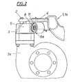
- Consoles 2 are cast onto the two halves 1 and 1a of the exhaust manifold of an internal combustion engine, to which a holder 3 is fastened.
- a double-flow exhaust gas turbine 3a is connected to the holder 3.
- two metal bellows 4 are initially provided, the holder 3 forming two channels 5 leading to one another.
- a total of six axial vibration dampers 6a, 6b are provided, of which the axes of the axial vibration dampers 6a lie in one plane, whereas the other three axial vibration dampers 6b are parallel are aligned with each other normal to this level, i.e. they pierce them.
- the axes of the axial vibration dampers 6b could also form a tripod with a tip lying outside the plane mentioned. Only two of the axial vibration dampers 6a are arranged in parallel axes.
- the axial vibration dampers 6a, 6b are accommodated in cup-shaped recesses 7 of the holder 3 and connected to sprues of the bracket 2 by bolts 8.
- Each bolt is surrounded by a sleeve 9, which has a collar 10 within the recess 7. Between this collar 10 and the recess bottom on the one hand or an annular disk 11 held by a snap ring on the other hand, cushions made of steel wire mesh are clamped for vibration damping, which naturally have a corresponding heat resistance and resilience.
- brackets 2 onto the exhaust manifold halves 1, 1a, but to fix them at a suitable point on the cylinder block.
Landscapes
- Engineering & Computer Science (AREA)
- Chemical & Material Sciences (AREA)
- Combustion & Propulsion (AREA)
- Mechanical Engineering (AREA)
- General Engineering & Computer Science (AREA)
- Exhaust Silencers (AREA)
Abstract
Description
- Die Erfindung betrifft eine Anordnung zur Befestigung der Abgasanlage am Abgassammler einer Brennkraftmaschine mit einem die Abgasanlage tragenden Halter, der zur Abgasführung zwischen Abgassammler und Abgasanlage über wenigstens einen Metallbalg am Abgassammler angeschlossen und über mit ihren Achsen in einer Ebene liegende Axialschwingungsdämpfer, vorzugsweise aus Stahldrahtgeflecht, mit dem Abgassammler oder dem Zylinderkopf verbunden ist. Eine derartige Befestigungsanordnung für eine Abgasanlage einer brennkraftmaschine ist durch die DE-OS 33 21 382 bekannt.
- Bei einer aus der Praxis bekannten Anordnung ist am Abgassammler eine Platte befestigt, die ihrerseits mit Hilfe zweier Axialschwingungsdämpfer aus Stahldrahtgeflecht den Halter trägt, an dem zwei Auspuffrohre angeschweißt sind, wobei dann zwischen dem Halter und der Platte für jedes dieser Auspuffrohre ein Metallbalg vorgesehen ist. Bei dieser Ausführung ergibt sich eine Verringerung des Schalldurchganges vom Abgassammler zu den Auspuffrohren, wobei die Axialschwingungsdämpfer bloß die Aufgabe haben, die Deformationen der Metallbälge in zulässigen Grenzen zu halten, ohne eine Schallbrücke zu bilden.
- Umfaßt die Abgasanlage aber eine Abgasturbine, die dann ebenfalls vom Halter getragen werden muß, so ergeben sich beim Betrieb des mit der Abgasanlage ausgerüsteten Kraftfahrzeuges bzw. beim Motorbetrieb selbst durch die Turbine vergleichsweise große dynamische Kräfte, die bei der bekannten Halteraufhängung unzulässig hohe Deformationen der Metallbälge mit sich bringen und so zu einer vorzeitigen Balgzerstörung führen würden.
- Demnach liegt der Erfindung die Aufgabe zugrunde, diese Mängel zu beseitigen und die eingangs geschilderte Anordnung so zu verbessern, daß trotz guter Körperschallunterbrechung auch bei Auftreten großer dynamischer Kräfte keine Beschädigung des Metallbalges bzw. der Metallbälge zu befürchten ist.
- Die Erfindung löst die gestellte Aufgabe dadurch, daß insgesamt sechs Axialschwingungsdämpfer um den Metallbalg bzw. die Metallbälge herum vorgesehen sind, daß aber nur die Achsen dreier dieser Dämpfer in der einen Ebene liegen, wobei höchstens zwei Achsen parallel angeordnet sind, und daß die Achsen der drei übrigen Dämpfer die Ebene durchstoßen und zueinander parallel verlaufen oder ein Dreibein bilden, dessen Spitze außerhalb der Ebene liegt. Durch diese Anordnung der Axialschwingungsdämpfer wird erreicht, daß unabhängig von der Art der Beanspruchung alle Dämpfer nur durch Axialkräfte belastet werden, also durch solche Kräfte, die die geringsten Deformationen des Dämpfers und damit auch der Metallbälge mit sich bringen. Querkräfte und Momente würden weit größere Deformationen zur Folge haben.
- Eine besonders günstige Konstruktion ergibt sich, wenn erfindungsgemäß die Axialschwingungsdämpfer in topfförmigen Ausnehmungen des gegossenen Halters oder von aus Abgassammler oder Zylinderkopf vorgesehenen Konsolen untergebracht und durch je einen den Ausnehmungsboden durchsetzenden Bolzen mit dem jeweils anderen Bauteil verbunden sind.
- Handelt es sich um eine Anlage mit zweiteiligem Abgassammler und über je einen Metallbalg mit dem Halter verbundenen Sammlerhälften, so bildet der gegossene halter zwei von den beiden Metallbälgen zueinander führende Kanäle zum Abschluß einer doppelflutigen Abgasturbine. Auf diese Weise wird eine gegenseitige Beeinflussung der getrennten Gasströme unterbunden und dennoch eine enge, für die Turbine notwendige Anordnung der Gaseintrittsöffnungen in die Turbine ermöglicht.
- In der Zeichnung ist der Erfindungsgegenstand in einem Ausführungsbeispiel dargestellt, und zwar zeigen
- Fig. 1 die erfindungswesentlichen Teile einer Anordnung zur Befestigung der Abgasanlage einer Brennkraftmaschine in Draufsicht und
- Fig. 2 in Seitenansicht.
- An den beiden Hälften 1 und 1a des Abgassammlers einer Brennkraftmaschine sind Konsolen 2 angegossen, an denen ein Halter 3 befestigt ist, Am Halter 3 ist eine zweiflutige Abgasturbine 3a angeschlossen. Zur Verbindung der Abgassammlerhälften 1, 1a mit dem Halter 3 sind zunächst zwei Metallbälge 4 vorgesehen, wobei der Halter 3 zwei zueinander führende Kanäle 5 bildet. Um den Halter 3 so an den Konsolen 2 zu befestigen, daß die Metallbälge 4 keine unzulässig großen Deformationen erleiden, sind insgesamt sechs Axialschwingungsdämpfer 6a, 6b vorgesehen, von denen die Achsen der Axialschwingungsdämpfer 6a in einer Ebene liegen, wogegen die übrigen drei Axialschwingungsdämpfer 6b parallel zueinander normal zu dieser Ebene ausgerichtet sind, also sie durchstoßen. Die Achsen der Axialschwingungsdämpfer 6b könnten auch ein Dreibein mit außerhalb der genannten Ebene liegender Spitze bilden. Von den Axialschwingungsdämpfern 6a sind nur zwei parallelachsig angeordnet.
- Die Axialschwingungsdämpfer 6a, 6b sind in topfförmigen Ausnehmungen 7 des Halters 3 untergebracht und mit Angüssen der Konsole 2 durch Bolzen 8 verbunden. Jeder Bolzen ist von einer Hülse 9 umgeben, die innerhalb der Ausnehmung 7 einen Bund 10 aufweist. Zwischen diesem Bund 10 und dem Ausnehmungsboden einerseits bzw. einer durch einen Sprengring gehaltenen Ringscheibe 11 andernseits sind zur Schwingungsdämpfung Polster aus Stahldrahtgeflecht eingespannt, die naturgemäß eine entsprechende Hitzebeständigkeit und Belastbarkeit aufweisen.
- Es wäre selbstverständlich auch möglich, die Konsolen 2 nicht an die Abgassammlerhälften 1, 1a anzugießen, sondern an geeigneter Stelle des Zylinderblockes zu befestigen.
Claims (3)
Applications Claiming Priority (2)
| Application Number | Priority Date | Filing Date | Title |
|---|---|---|---|
| AT308687 | 1987-11-24 | ||
| AT3086/87 | 1987-11-24 |
Publications (2)
| Publication Number | Publication Date |
|---|---|
| EP0318457A1 true EP0318457A1 (de) | 1989-05-31 |
| EP0318457B1 EP0318457B1 (de) | 1991-08-21 |
Family
ID=3545121
Family Applications (1)
| Application Number | Title | Priority Date | Filing Date |
|---|---|---|---|
| EP88890284A Expired - Lifetime EP0318457B1 (de) | 1987-11-24 | 1988-11-11 | Anordnung zur Befestigung der Abgasanlage am Abgassammler einer Brennkraftmaschine |
Country Status (8)
| Country | Link |
|---|---|
| US (1) | US4860852A (de) |
| EP (1) | EP0318457B1 (de) |
| JP (1) | JPH01167407A (de) |
| CA (1) | CA1302900C (de) |
| DE (1) | DE3838707A1 (de) |
| GB (1) | GB2212858B (de) |
| SU (1) | SU1706397A3 (de) |
| YU (1) | YU215588A (de) |
Cited By (1)
| Publication number | Priority date | Publication date | Assignee | Title |
|---|---|---|---|---|
| AT509691B1 (de) * | 2010-03-18 | 2013-09-15 | Avl List Gmbh | Brennkraftmaschine mit einer verbindungsanordnung für einen zylinderkopf |
Families Citing this family (9)
| Publication number | Priority date | Publication date | Assignee | Title |
|---|---|---|---|---|
| US20050040576A1 (en) * | 2003-08-20 | 2005-02-24 | Ernest Oxenknecht | Multi-axis isolator and assembly for the same |
| KR101474846B1 (ko) * | 2008-03-13 | 2014-12-19 | 보르그워너 인코퍼레이티드 | 내연 기관의 배기 매니폴드 |
| DE102008019675A1 (de) * | 2008-04-18 | 2010-02-18 | Dr. Ing. H.C. F. Porsche Aktiengesellschaft | Abgasanlage für eine Brennkraftmaschine |
| GB2494144A (en) | 2011-08-30 | 2013-03-06 | Gm Global Tech Operations Inc | Turbocharger to exhaust manifold connection |
| JP6167043B2 (ja) * | 2014-01-09 | 2017-07-19 | 三菱重工業株式会社 | 翼及びタービン |
| CN104329155A (zh) * | 2014-11-19 | 2015-02-04 | 柳州市莫尔斯汽配制造有限公司 | 汽车排气管结构 |
| EP3106686B1 (de) * | 2015-06-15 | 2018-09-12 | Ansaldo Energia IP UK Limited | Dämpfungsmittel für komponenten in einer turbomaschine und verfahren zur montage der besagten dämpfungsmittel |
| US10156171B2 (en) | 2015-08-07 | 2018-12-18 | Cummins Emission Solutions Inc. | Mounting aftertreatment systems from service joints |
| CN105545441A (zh) * | 2016-01-27 | 2016-05-04 | 徐磊 | 带有补偿功能的排气歧管 |
Citations (3)
| Publication number | Priority date | Publication date | Assignee | Title |
|---|---|---|---|---|
| DE2701022A1 (de) * | 1977-01-12 | 1978-07-13 | Volkswagenwerk Ag | Gasdichte rohrverbindung, insbesondere fuer eine abgasleitung |
| DE3310494A1 (de) * | 1982-05-28 | 1983-12-01 | Motoren-Werke Mannheim AG vorm. Benz Abt. stationärer Motorenbau, 6800 Mannheim | Einrichtung zur kompensierung der thermisch bedingten laengenaenderungen von abgasrohren bei einem aufgeladenen v-motor mit nur einem abgasturbolader |
| US4475341A (en) * | 1981-05-19 | 1984-10-09 | Honda Giken Kogyo Kabushiki Kaisha | Exhaust manifold device for engines |
Family Cites Families (4)
| Publication number | Priority date | Publication date | Assignee | Title |
|---|---|---|---|---|
| US2160808A (en) * | 1938-02-15 | 1939-06-06 | Harris Products Company | Exhaust pipe and muffler support |
| US4280588A (en) * | 1979-09-26 | 1981-07-28 | Veldhuizen John V | Anti-pollution manifold for I.C.E. |
| US4428338A (en) * | 1981-05-13 | 1984-01-31 | Hans List | Internal combustion engine |
| DE8222490U1 (de) * | 1982-08-10 | 1982-11-11 | IWK Regler und Kompensatoren GmbH, 7513 Stutensee | Einrichtung zum gelenkigen verbinden von motor und abgasanlage |
-
1988
- 1988-11-11 EP EP88890284A patent/EP0318457B1/de not_active Expired - Lifetime
- 1988-11-14 US US07/271,119 patent/US4860852A/en not_active Expired - Fee Related
- 1988-11-15 DE DE3838707A patent/DE3838707A1/de not_active Ceased
- 1988-11-22 JP JP63293778A patent/JPH01167407A/ja active Granted
- 1988-11-23 SU SU884356940A patent/SU1706397A3/ru active
- 1988-11-23 YU YU02155/88A patent/YU215588A/xx unknown
- 1988-11-23 CA CA000583845A patent/CA1302900C/en not_active Expired - Fee Related
- 1988-11-24 GB GB8827444A patent/GB2212858B/en not_active Expired - Fee Related
Patent Citations (3)
| Publication number | Priority date | Publication date | Assignee | Title |
|---|---|---|---|---|
| DE2701022A1 (de) * | 1977-01-12 | 1978-07-13 | Volkswagenwerk Ag | Gasdichte rohrverbindung, insbesondere fuer eine abgasleitung |
| US4475341A (en) * | 1981-05-19 | 1984-10-09 | Honda Giken Kogyo Kabushiki Kaisha | Exhaust manifold device for engines |
| DE3310494A1 (de) * | 1982-05-28 | 1983-12-01 | Motoren-Werke Mannheim AG vorm. Benz Abt. stationärer Motorenbau, 6800 Mannheim | Einrichtung zur kompensierung der thermisch bedingten laengenaenderungen von abgasrohren bei einem aufgeladenen v-motor mit nur einem abgasturbolader |
Cited By (1)
| Publication number | Priority date | Publication date | Assignee | Title |
|---|---|---|---|---|
| AT509691B1 (de) * | 2010-03-18 | 2013-09-15 | Avl List Gmbh | Brennkraftmaschine mit einer verbindungsanordnung für einen zylinderkopf |
Also Published As
| Publication number | Publication date |
|---|---|
| GB2212858A (en) | 1989-08-02 |
| US4860852A (en) | 1989-08-29 |
| GB8827444D0 (en) | 1988-12-29 |
| JPH01167407A (ja) | 1989-07-03 |
| DE3838707A1 (de) | 1989-06-08 |
| SU1706397A3 (ru) | 1992-01-15 |
| EP0318457B1 (de) | 1991-08-21 |
| YU215588A (en) | 1990-08-31 |
| CA1302900C (en) | 1992-06-09 |
| GB2212858B (en) | 1991-06-26 |
| JPH0240851B2 (de) | 1990-09-13 |
Similar Documents
| Publication | Publication Date | Title |
|---|---|---|
| DE3943729C2 (de) | Zylinderkopf einer Brennkraftmaschine | |
| DE3217959C2 (de) | Vorrichtung zur vibrationsisolierten Befestigung eines Fahrschemels oder Aggregathalters | |
| EP0318457B1 (de) | Anordnung zur Befestigung der Abgasanlage am Abgassammler einer Brennkraftmaschine | |
| DE4324791A1 (de) | Zylinderkopfanordnung einer Brennkraftmaschine | |
| DE4401827C2 (de) | Vorrichtung zur gelenkigen Verbindung von Rohren einer Abgasanlage | |
| DE4432073C2 (de) | Vorrichtung zur Befestigung von Turboladern | |
| DE19814975B4 (de) | Trägersystem für Nutzfahrzeuge | |
| EP0827847A2 (de) | Zentrallager für eine Hinterachse eines Kraftfahrzeuges | |
| DE3841666A1 (de) | Befestigungsvorrichtung zum befestigen rohrfoermiger bauteile, durch die ein fluid hindurchstroemt | |
| DE19708759B4 (de) | Trägeraufbau für einen Fahrzeugluftfilter | |
| DE4007724A1 (de) | Russfilter fuer dieselmotoren | |
| DE3415780A1 (de) | Kraftstoffeinspritzsystem | |
| DE4116653A1 (de) | Ansauganlage fuer eine mehrzylindrige brennkraftmaschine | |
| AT404390B (de) | Brennkraftmaschine mit einem abschnittsweise gekühlten ventilsitzring | |
| DE102008045461A1 (de) | Akustische Seitenabdeckung für einen Motor | |
| DE102004023585B4 (de) | Katalysatorbefestigung, Befestigung am Flansch Katalysatorausgang, ohne Schweißverbindung | |
| DE4125249C2 (de) | Elastische Befestigungsvorrichtung zur Verbindung eines Ansaugrohres mit einer Verbrennungskraftmaschine | |
| DE19753689A1 (de) | Aufhängungsvorrichtung für eine Element wie einen Vergaser eines Verbrennungsmotors | |
| DE19912166C2 (de) | Montagewerkzeug zum Montieren von Kolben mit radial nach außen spannenden Kolbenringen in Zylindern | |
| EP0708232A2 (de) | Vorrichtung mit mindestens einer Drosselklappe | |
| EP0233509A1 (de) | Vorrichtung zur Halterung von Monolithkatalysatoren | |
| EP0775819A1 (de) | Kolben für Brennkraftmaschinen | |
| EP0985843A1 (de) | Zweiteilige Bremsscheibe | |
| DE19728815A1 (de) | Rohrverbindung zweier sich überlappender Rohre | |
| EP0937873A1 (de) | Anschlussvorrichtung für ein Abgasrohr einer Brennkraftmaschine |
Legal Events
| Date | Code | Title | Description |
|---|---|---|---|
| PUAI | Public reference made under article 153(3) epc to a published international application that has entered the european phase |
Free format text: ORIGINAL CODE: 0009012 |
|
| AK | Designated contracting states |
Kind code of ref document: A1 Designated state(s): FR IT NL SE |
|
| 17P | Request for examination filed |
Effective date: 19890404 |
|
| 17Q | First examination report despatched |
Effective date: 19891220 |
|
| GRAA | (expected) grant |
Free format text: ORIGINAL CODE: 0009210 |
|
| AK | Designated contracting states |
Kind code of ref document: B1 Designated state(s): FR IT NL SE |
|
| ITF | It: translation for a ep patent filed |
Owner name: DE DOMINICIS & MAYER S.R.L. |
|
| PGFP | Annual fee paid to national office [announced via postgrant information from national office to epo] |
Ref country code: SE Payment date: 19911014 Year of fee payment: 4 |
|
| PGFP | Annual fee paid to national office [announced via postgrant information from national office to epo] |
Ref country code: NL Payment date: 19911130 Year of fee payment: 4 |
|
| EN | Fr: translation not filed | ||
| REG | Reference to a national code |
Ref country code: FR Ref legal event code: AR |
|
| PLBE | No opposition filed within time limit |
Free format text: ORIGINAL CODE: 0009261 |
|
| STAA | Information on the status of an ep patent application or granted ep patent |
Free format text: STATUS: NO OPPOSITION FILED WITHIN TIME LIMIT |
|
| 26N | No opposition filed | ||
| PG25 | Lapsed in a contracting state [announced via postgrant information from national office to epo] |
Ref country code: SE Effective date: 19921112 |
|
| ET | Fr: translation filed | ||
| REG | Reference to a national code |
Ref country code: FR Ref legal event code: BR |
|
| PG25 | Lapsed in a contracting state [announced via postgrant information from national office to epo] |
Ref country code: NL Effective date: 19930601 |
|
| NLV4 | Nl: lapsed or anulled due to non-payment of the annual fee | ||
| PGFP | Annual fee paid to national office [announced via postgrant information from national office to epo] |
Ref country code: FR Payment date: 19941012 Year of fee payment: 7 |
|
| EUG | Se: european patent has lapsed |
Ref document number: 88890284.8 Effective date: 19930610 |
|
| PG25 | Lapsed in a contracting state [announced via postgrant information from national office to epo] |
Ref country code: FR Effective date: 19960731 |
|
| REG | Reference to a national code |
Ref country code: FR Ref legal event code: ST |
|
| PG25 | Lapsed in a contracting state [announced via postgrant information from national office to epo] |
Ref country code: IT Free format text: LAPSE BECAUSE OF NON-PAYMENT OF DUE FEES;WARNING: LAPSES OF ITALIAN PATENTS WITH EFFECTIVE DATE BEFORE 2007 MAY HAVE OCCURRED AT ANY TIME BEFORE 2007. THE CORRECT EFFECTIVE DATE MAY BE DIFFERENT FROM THE ONE RECORDED. Effective date: 20051111 |