EP0707943B1 - Verfahren und Vorrichtung zur kontinuierlichen Herstellung von glasfaserronden für Schleif- und Trennscheiben - Google Patents
Verfahren und Vorrichtung zur kontinuierlichen Herstellung von glasfaserronden für Schleif- und Trennscheiben Download PDFInfo
- Publication number
- EP0707943B1 EP0707943B1 EP94116382A EP94116382A EP0707943B1 EP 0707943 B1 EP0707943 B1 EP 0707943B1 EP 94116382 A EP94116382 A EP 94116382A EP 94116382 A EP94116382 A EP 94116382A EP 0707943 B1 EP0707943 B1 EP 0707943B1
- Authority
- EP
- European Patent Office
- Prior art keywords
- winding
- station
- thread
- pins
- wound
- Prior art date
- Legal status (The legal status is an assumption and is not a legal conclusion. Google has not performed a legal analysis and makes no representation as to the accuracy of the status listed.)
- Expired - Lifetime
Links
Images

Classifications
-
- B—PERFORMING OPERATIONS; TRANSPORTING
- B29—WORKING OF PLASTICS; WORKING OF SUBSTANCES IN A PLASTIC STATE IN GENERAL
- B29C—SHAPING OR JOINING OF PLASTICS; SHAPING OF MATERIAL IN A PLASTIC STATE, NOT OTHERWISE PROVIDED FOR; AFTER-TREATMENT OF THE SHAPED PRODUCTS, e.g. REPAIRING
- B29C70/00—Shaping composites, i.e. plastics material comprising reinforcements, fillers or preformed parts, e.g. inserts
- B29C70/04—Shaping composites, i.e. plastics material comprising reinforcements, fillers or preformed parts, e.g. inserts comprising reinforcements only, e.g. self-reinforcing plastics
- B29C70/28—Shaping operations therefor
- B29C70/30—Shaping by lay-up, i.e. applying fibres, tape or broadsheet on a mould, former or core; Shaping by spray-up, i.e. spraying of fibres on a mould, former or core
- B29C70/34—Shaping by lay-up, i.e. applying fibres, tape or broadsheet on a mould, former or core; Shaping by spray-up, i.e. spraying of fibres on a mould, former or core and shaping or impregnating by compression, i.e. combined with compressing after the lay-up operation
- B29C70/347—Shaping by lay-up, i.e. applying fibres, tape or broadsheet on a mould, former or core; Shaping by spray-up, i.e. spraying of fibres on a mould, former or core and shaping or impregnating by compression, i.e. combined with compressing after the lay-up operation combined with compressing after the winding of lay-ups having a non-circular cross-section, e.g. flat spiral windings
-
- B—PERFORMING OPERATIONS; TRANSPORTING
- B29—WORKING OF PLASTICS; WORKING OF SUBSTANCES IN A PLASTIC STATE IN GENERAL
- B29C—SHAPING OR JOINING OF PLASTICS; SHAPING OF MATERIAL IN A PLASTIC STATE, NOT OTHERWISE PROVIDED FOR; AFTER-TREATMENT OF THE SHAPED PRODUCTS, e.g. REPAIRING
- B29C53/00—Shaping by bending, folding, twisting, straightening or flattening; Apparatus therefor
- B29C53/56—Winding and joining, e.g. winding spirally
- B29C53/564—Winding and joining, e.g. winding spirally for making non-tubular articles
-
- B—PERFORMING OPERATIONS; TRANSPORTING
- B29—WORKING OF PLASTICS; WORKING OF SUBSTANCES IN A PLASTIC STATE IN GENERAL
- B29C—SHAPING OR JOINING OF PLASTICS; SHAPING OF MATERIAL IN A PLASTIC STATE, NOT OTHERWISE PROVIDED FOR; AFTER-TREATMENT OF THE SHAPED PRODUCTS, e.g. REPAIRING
- B29C53/00—Shaping by bending, folding, twisting, straightening or flattening; Apparatus therefor
- B29C53/80—Component parts, details or accessories; Auxiliary operations
- B29C53/8008—Component parts, details or accessories; Auxiliary operations specially adapted for winding and joining
-
- B—PERFORMING OPERATIONS; TRANSPORTING
- B29—WORKING OF PLASTICS; WORKING OF SUBSTANCES IN A PLASTIC STATE IN GENERAL
- B29C—SHAPING OR JOINING OF PLASTICS; SHAPING OF MATERIAL IN A PLASTIC STATE, NOT OTHERWISE PROVIDED FOR; AFTER-TREATMENT OF THE SHAPED PRODUCTS, e.g. REPAIRING
- B29C53/00—Shaping by bending, folding, twisting, straightening or flattening; Apparatus therefor
- B29C53/80—Component parts, details or accessories; Auxiliary operations
- B29C53/82—Cores or mandrels
- B29C53/821—Mandrels especially adapted for winding and joining
- B29C53/828—Arrangements comprising a plurality of cores or mandrels, e.g. to increase production speed
Definitions
- the present invention relates to a method for Manufacture of, in particular, as reinforcement for grinding and Cutting glass fiber rounds, in which a resinous Glass fiber thread according to a predetermined winding pattern several winding points evenly distributed over the circumference is wrapped and then fixed. Furthermore concerns the invention a winding device for performing the Procedure.
- the Winding body by cutting the previously fixed glass fiber threads around the edge of the template in two glass fiber rounds divided, which was previously pressed to fix the crosshairs were.
- This known method produces far less Waste - a reduction of about 25% - than when punching out of round blanks made of rectangular mesh. Indeed can not waste in the known process Avoid completely, especially as a glass dust when Separation of the winding body occurs. In the known method it is also a discontinuous process. As soon as the actual winding process is finished, the Winding device to be stopped. The cut off Thread must be threaded again and clamped to the next winding blank to be able to wrap, resulting in long downtimes leads to the winding device and thus a reduced Production output with increased production costs Consequence. In the known method, it can also be used in various Steps to get tangled and hooking the blanks after the cutting process so that Interruptions in finishing arise that affect the workflow affect.
- the object of the invention is the method of to the extent specified in the preamble of claim 1 improve that continuous and waste-free manufacturing of glass fiber rounds when the susceptibility to interference is reduced and increasing the throughput.
- the Winding process should be simplified so that the desired Winding pattern can be produced precisely.
- a constant pinching and re-threading the thread after each winding operation should be dropped.
- the object of the invention continues to exist therein an apparatus for performing the method to create with which continuous work is possible is and has a compact structure.
- the winding takes place continuously, successively and in the winding station through the winding pattern predetermined partial wrapping around the winding points to the finished winding blank. Then the finished winding blank via an empty station to a press station in time transported, the blanks in the individual stations consistently connected with each other via the glass fiber thread stay.
- the press station the form is glued the threads at their crossing points under the influence of pressure and temperature fixed by means of a press ram. Only or towards the end of the fixing process and in any case before Removing the finished glass fiber blank from the removal station the glass fiber thread is cut, with no waste arises.
- the glass fiber thread continuously from a trigger device e.g. a coil is pulled off. So there is no cutting of the round blanks by peripheral cutting required so that the formation of glass dust is avoided.
- the winding time is about 8 seconds, i.e. during this time is simultaneously in parallel processing wound on the existing stations, fixed by pressing, the thread separation is carried out and the finished glass fiber blank taken.
- a device for carrying out the method, which has a rotating rotary table with several, e.g. four, touching, i.e. in the circumferential direction without spaced stations, namely a winding station, an empty station, a press station and a removal station. Everybody is there Station as a shaping island with winding points arranged in a circle formed, the winding points by about cone-shaped, axially controlled thread take-up (so-called winding pins) are formed.
- a rotating winding head preferably in training arranged as a winding spindle, the one required for winding Thread from a thread take-off device, e.g. a coil with Thread store, subtracts.
- the winding head is infinitely variable adjustable AC servo motor driven. Above the press station there is a press ram that can be moved in the axial direction. Finally, the removal station is a removal device for the automatic removal of the finished glass fiber blanks assigned, this removal device preferably is designed as a gripper.
- the winding pins are in Axially slidably mounted and for this purpose in each case connected to a pneumatic cylinder with which the Pins can be controlled individually and in different axial positions can be moved so that they are in the highest Position catch the thread in a lowered position Hold the thread and pull it back when you pull it back completely and thus release the winding blank. There is a chain of functions between the winding head rotation and the axial pin movement of the winding points.
- the device shown in the drawing consists essentially from a rotary table rotatably mounted around axis 1 2.
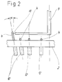
- the rotary table 2 carries four in total Identically formed so-called formers 3, each formed by the circularly arranged winding points 4 will. These winding points 4 are cone-shaped elements (so-called pins) trained. This is particularly evident in Fig. 2 clearly recognizable, which will be discussed in more detail below becomes.
- the four formers 3 are in the circumferential direction distributed so that they touch each other.
- the device has a total of four stations, namely the actual winding station 5, an empty station 6, the press or Fixing station 7 and the removal station 8.
- the winding station 5 is with the rotating, continuously driven Winding head 9 equipped with the glass fiber thread 10 of the coil or the like, not shown, with an associated thread store subtracts and with its help in a certain Way to achieve the desired winding pattern each Winding points or pins 4 are wrapped around.
- the drive of the winding head which is preferably designed as a winding spindle 9 is carried out continuously by a not shown adjustable AC servo motor.
- the empty station 6 only serves as a buffer for realizing a continuous winding process. In the area of the coil there is still one to protect the thread Not shown thread deflection system provided.
- the following press station 7 has an axially movable press ram 11, while the removal station 8 with a (not further shown) e.g. removal device designed as a gripper Is provided. Between the press station 7 and the Removal station 8 is also a cutting device 14 is arranged, which also between the empty station 6 and the press station 7 could be provided.
- Fig. 2 shows that the winding points 4 as cone-shaped elements or as pins are formed.
- This Pins 4 are each with their own pneumatic cylinder 12 in connection and are movable in the axial direction in the rotary indexing table 2 stored.
- Each pneumatic cylinder 12 is PLC-controlled.
- the pins 4 are in three different axial positions after appropriate control of the respective pneumatic cylinder 12 spent or moved, namely in the Thread catching position, at Pin 4 furthest above the surface of the rotary indexing table 2 protrudes (see FIG. 2) into which Working position with just a little over the surface of the rotary table 2 above pin 4, in which the looped thread is held, and finally in the removal position Pin 4 fully retracted, where the finished blank can be removed.
- the resin-coated thread 10 is provided on a take-off device (eg coil with thread tensioning system and storage) and fed to the winding head 9 via various deflection mechanisms (not shown).
- a take-off device eg coil with thread tensioning system and storage
- the winding head 9 rotates with the thread 10 above the shaping island 3 located in the station 5.
- the thread pickups 4 forming the shaping island 3 can be individually extended and retracted. In the extended state, they are partially wrapped in the thread 10 when passing through the winding head 9, in the retracted state (working position) they remain unoccupied.
- a certain winding pattern can be generated by extending and retracting certain thread pickups 4 (pins) at certain times in connection with the function of the rotating winding head 9.
- the thread winding takes place via the continuously adjustable winding head 9, which is designed, for example, as a winding spindle, from above and on one side.
- a corresponding PLC control program for the winding pattern to be produced is used to control the winding pins 4 in the functional context with the winding spindle speed (angle of rotation!).
- the winding blank 13 comes from the empty station 6 to the pressing station 7.
- the pressing die 11 moves onto the winding blank 13 and presses with a defined pressure and a defined temperature within a defined time. This results in the threads sticking and fixing in the area of their crossing points.
- the thread 10 is cut off tangentially by means of the cutting device 14, with no waste occurring.
- the ram 11 starts up; at the same time all pins 4 are withdrawn by the control.
- the winding blank 13 arrives at the removal station 8, from which the exposed blank 13 is removed and stacked or transferred to a subsequent device.
- the shaping island 3 arrives at the winding station 5 in the next cycle.
Landscapes
- Engineering & Computer Science (AREA)
- Mechanical Engineering (AREA)
- Chemical & Material Sciences (AREA)
- Composite Materials (AREA)
- Moulding By Coating Moulds (AREA)
- Manufacture, Treatment Of Glass Fibers (AREA)
Description
- Fig. 1
- die Vorrichtung zum Herstellen der Ronden im kontinuierlichen Wickelverfahren, schematisch dargestellt, in der Draufsicht mit Wickelstation, Leerstation, Preßstation und Entnahmestation, und
- Fig. 2
- in vergrößerter abgebrochener seitlicher Ansicht die Wickelstation mit Wickelkopf.
Claims (10)
- Verfahren zur Herstellung von insbesondere als Armierung von Schleif- und Trennscheiben dienenden Glasfaserronden, bei dem ein beharzter Glasfaserfaden (10) nach einem vorgegebenen Wickelmuster über mehrere gleichmäßig über den Umfang verteilte Wickelpunkte (4) gewickelt und anschließend fixiert wird, dadurch gekennzeichnet, daß das Wickeln kontinuierlich aufeinanderfolgend und durch teilweises Umschlingen der Wickelpunkte (4) bis zur fertigen Wickelronde (13) durchgeführt, die fertige Wickelronde (13) sodann über eine Leerstation (6) bis zu einer Preßstation (7) weitergetaktet, in der Preßstation (7) fixiert und schließlich zu einer Entnahmestation (8) getaktet wird, wobei die kontinuierlich und in zeitlicher Parallelbearbeitung taktweise erzeugten Wickelronden (13) über den Glasfaserfaden (10) jeweils im Berührungspunkt der Wickelronden (13) zusammenhängen und dieser Faden (10) erst während oder nach dem Fixieren bzw. vor dem Entnehmen der Wickelronden (13) abfallos durchtrennt wird.
- Verfahren nach Anspruch 1, dadurch gekennzeichnet, daß der Wickelvorgang jeweils einseitig unter Erzeugung der Wickelmuster durchgeführt wird, wobei der Glasfaserfaden (10) kontinuierlich von einer Abzugsvorrichtung (z.B. Coil mit Fadenspannsystem) abgezogen wird.
- Verfahren nach Anspruch 1 oder 2, dadurch gekennzeichnet, daß das Fixieren der überkreuzten Fäden des Wickelmusters in der Preßstation (7) durch Pressen mit einem definierten Druck und einer definierten Temperatur durchgeführt wird.
- Vorrichtung zur Durchführung des Verfahrens nach einem der Ansprüche 1 bis 3, dadurch gekennzeichnet, daß ein drehbar gelagerter Rundtisch (2) zur Parallelbearbeitung mehrere Stationen, wie Wickelstation (5), Leerstation (6), Preßstation (7) und Entnahmestation (8) aufweist, und die kreisförmig angeordneten, jeweils eine Formgeberinsel (3) bildenden Wickelpunkte (4) als Fadenaufnehmer ausgebildet sind, wobei über der Wickelstation (5) ein rotierender Wickelkopf (9) und über der Preßstation (7) ein axial verlagerbarer Preßstempel (11) angeordnet ist, während der Entnahmestation (8) eine Entnahmeeinrichtung zugeordnet ist.
- Vorrichtung nach Anspruch 4, dadurch gekennzeichnet, daß der Wickelkopf (9) als Wickelspindel ausgebildet und mit einem fadenschonenden Wickelumlenksystem und stufenlos regelbarem AC-Servomotor ausgerüstet ist.
- Vorrichtung nach Anspruch 4 oder 5, dadurch gekennzeichnet, daß die kreisförmig angeordneten Formgeberinseln (3) auf dem Rundtisch (2) in Umfangsrichtung gleichmäßig, sich gegenseitig tangierend, vorgesehen sind.
- Vorrichtung nach einem der Ansprüche 4 bis 6, dadurch gekennzeichnet, daß die Fadenaufnehmer (4) als axial verschiebbar gelagerte Zapfen (Pins) ausgebildet sind, deren Axialbewegung im Funktionszusammenhang mit der Drehbewegung des Wickelkopfes (9) steht.
- Vorrichtung nach Anspruch 7, dadurch gekennzeichnet, daß den Zapfen bzw. Pins (4) jeweils eigene SPS-gesteuerte Pneumatikzylinder (12) zugeordnet sind, mit denen die Zapfen (4) über die SPS-Steuerung in Funktionszusammenhang mit dem Wickelkopf-Servomotor einzeln ansteuerbar und axial verschiebbar sind.
- Vorrichtung nach einem der Ansprüche 4 bis 8, dadurch gekennzeichnet, daß im Bereich der Preßstation (7) eine Schneideinrichtung (14) zum Durchtrennen des Glasfaserfadens (10) je Ronde angeordnet ist.
- Vorrichtung nach einem der Ansprüche 4 bis 9, dadurch gekennzeichnet, daß die Wickelpins (4) in bezug auf die Mittellängsachse jeder Formgeberinsel (3) geringfügig gegenüber der Senkrechten nach außen geneigt (Winkel α) sind, derart, daß die Wickelpins (4) auf einem axial nach unten konvergierenden Kegelmantel liegen.
Priority Applications (3)
| Application Number | Priority Date | Filing Date | Title |
|---|---|---|---|
| DE59406624T DE59406624D1 (de) | 1994-10-18 | 1994-10-18 | Verfahren und Vorrichtung zur kontinuierlichen Herstellung von glasfaserronden für Schleif- und Trennscheiben |
| EP94116382A EP0707943B1 (de) | 1994-10-18 | 1994-10-18 | Verfahren und Vorrichtung zur kontinuierlichen Herstellung von glasfaserronden für Schleif- und Trennscheiben |
| AT94116382T ATE169266T1 (de) | 1994-10-18 | 1994-10-18 | Verfahren und vorrichtung zur kontinuierlichen herstellung von glasfaserronden für schleif- und trennscheiben |
Applications Claiming Priority (1)
| Application Number | Priority Date | Filing Date | Title |
|---|---|---|---|
| EP94116382A EP0707943B1 (de) | 1994-10-18 | 1994-10-18 | Verfahren und Vorrichtung zur kontinuierlichen Herstellung von glasfaserronden für Schleif- und Trennscheiben |
Publications (2)
| Publication Number | Publication Date |
|---|---|
| EP0707943A1 EP0707943A1 (de) | 1996-04-24 |
| EP0707943B1 true EP0707943B1 (de) | 1998-08-05 |
Family
ID=8216396
Family Applications (1)
| Application Number | Title | Priority Date | Filing Date |
|---|---|---|---|
| EP94116382A Expired - Lifetime EP0707943B1 (de) | 1994-10-18 | 1994-10-18 | Verfahren und Vorrichtung zur kontinuierlichen Herstellung von glasfaserronden für Schleif- und Trennscheiben |
Country Status (3)
| Country | Link |
|---|---|
| EP (1) | EP0707943B1 (de) |
| AT (1) | ATE169266T1 (de) |
| DE (1) | DE59406624D1 (de) |
Families Citing this family (1)
| Publication number | Priority date | Publication date | Assignee | Title |
|---|---|---|---|---|
| US5913994A (en) * | 1996-08-30 | 1999-06-22 | Norton Company | Method for fabricating abrasive discs |
Family Cites Families (4)
| Publication number | Priority date | Publication date | Assignee | Title |
|---|---|---|---|---|
| US4289564A (en) * | 1980-04-25 | 1981-09-15 | Arthur E. Thomson | Stranding apparatus |
| DE3735778C2 (de) * | 1987-10-22 | 1995-04-06 | Josef Baer Maschinenfabrik Gmb | Faserwickelmaschine zur Herstellung von Verbundstoffkörpern |
| DE3819199A1 (de) * | 1988-06-06 | 1989-12-07 | Leurop Leutheusser Kg | Verfahren zur herstellung von glasfaserronden fuer schleif- oder trennscheiben und vorrichtung zur durchfuehrung des verfahrens |
| DE4234083A1 (de) * | 1992-10-09 | 1994-04-14 | Olbo Textilwerke Gmbh | Verfahren und Vorrichtung zum Legen von Fäden |
-
1994
- 1994-10-18 AT AT94116382T patent/ATE169266T1/de not_active IP Right Cessation
- 1994-10-18 EP EP94116382A patent/EP0707943B1/de not_active Expired - Lifetime
- 1994-10-18 DE DE59406624T patent/DE59406624D1/de not_active Expired - Fee Related
Also Published As
| Publication number | Publication date |
|---|---|
| EP0707943A1 (de) | 1996-04-24 |
| DE59406624D1 (de) | 1998-09-10 |
| ATE169266T1 (de) | 1998-08-15 |
Similar Documents
| Publication | Publication Date | Title |
|---|---|---|
| CH643409A5 (de) | Vorrichtung zum wickeln von spulen fuer statoren elektrischer maschinen. | |
| EP1545981B1 (de) | VERFAHREN ZUR ENTFERNUNG VON DR HTEN ODER B NDERN VON G EPRESSTEN ROHSTOFFBALLEN SOWIE DRAHTWICKELVORRICHTUNG ZUR DURCHFÜHRUNG DES VERFAHRENS | |
| DE3603761C2 (de) | ||
| EP0611612A1 (de) | Drückwalzmschine | |
| EP0707943B1 (de) | Verfahren und Vorrichtung zur kontinuierlichen Herstellung von glasfaserronden für Schleif- und Trennscheiben | |
| DE3815998C2 (de) | ||
| DE3819199C2 (de) | ||
| DE877592C (de) | Verfahren und Vorrichtung zur Herstellung von Garnpackungen | |
| EP0016359B1 (de) | Verfahren und Vorrichtung zur Herstellung eines Balles aus Schaumstoff mit Oberflächenprägung | |
| DE2739239C2 (de) | Vorrichtung zum Herstellen eines rohrförmigen Hohlkörpers, insbes. von Verpackungsteilen aus mehrschichtigem Verbundmaterial | |
| DE3337243A1 (de) | Einrichtung zur fertigung gepresster gegenstaende | |
| DE3840788A1 (de) | Verfahren und vorrichtung zum herstellen von formkoerpern aus faserverbundwerkstoff | |
| DE69727890T2 (de) | Verfahren und Maschine zur Herstellung eines scheibenförmigen Elementes aus einem kontinuierlichen Faden sowie ein hergestelltes scheibenförmiges Element | |
| DE2423914A1 (de) | Maschine zur herstellung von rohren und dgl. aus verstaerktem harzmaterial | |
| EP0331638B1 (de) | Spulenwechseleinrichtung an einer Spinnvorrichtung | |
| DE4306624C2 (de) | Vorrichtung zur Herstellung gewellter Wicklungen | |
| EP4086070B1 (de) | Vorrichtung und verfahren zur herstellung von kernpaketen für fahrzeugluftreifen | |
| DE3022041C2 (de) | Spulenwechselvorrichtung | |
| DE2902022C2 (de) | Verfahren zum Aufbau von Luftreifen und Einrichtung zur Ausführung desselben | |
| DE4308676A1 (de) | Vorrichtung zum automatischen Zuführen, Eingeben und Abführen von Werkstücken bei Werkzeugmaschinen | |
| DE4039112A1 (de) | Verfahren zum kreuzweise verschweissen von aus einer kassette herausragenden thermoplastbaendern und vorrichtung zur durchfuehrung | |
| DE3641746A1 (de) | Wickelmaschine fuer spulen, insbesondere smd-spulen | |
| DE1452598A1 (de) | Maschine zur automatischen Herstellung von Verschlusskapseln | |
| DE2606689A1 (de) | Vorrichtung zum automatischen abfuehren von werkstuecken aus schneidpressen | |
| DE2401400A1 (de) | Vorrichtung zum automatischen zu- und abfuehren von werkstuecken an montage- und/oder bearbeitungsmaschinen |
Legal Events
| Date | Code | Title | Description |
|---|---|---|---|
| PUAI | Public reference made under article 153(3) epc to a published international application that has entered the european phase |
Free format text: ORIGINAL CODE: 0009012 |
|
| AK | Designated contracting states |
Kind code of ref document: A1 Designated state(s): AT CH DE ES FR GB IT LI NL |
|
| 17P | Request for examination filed |
Effective date: 19960522 |
|
| GRAG | Despatch of communication of intention to grant |
Free format text: ORIGINAL CODE: EPIDOS AGRA |
|
| 17Q | First examination report despatched |
Effective date: 19971023 |
|
| GRAG | Despatch of communication of intention to grant |
Free format text: ORIGINAL CODE: EPIDOS AGRA |
|
| GRAH | Despatch of communication of intention to grant a patent |
Free format text: ORIGINAL CODE: EPIDOS IGRA |
|
| GRAH | Despatch of communication of intention to grant a patent |
Free format text: ORIGINAL CODE: EPIDOS IGRA |
|
| GRAA | (expected) grant |
Free format text: ORIGINAL CODE: 0009210 |
|
| AK | Designated contracting states |
Kind code of ref document: B1 Designated state(s): AT CH DE ES FR GB IT LI NL |
|
| PG25 | Lapsed in a contracting state [announced via postgrant information from national office to epo] |
Ref country code: NL Free format text: LAPSE BECAUSE OF FAILURE TO SUBMIT A TRANSLATION OF THE DESCRIPTION OR TO PAY THE FEE WITHIN THE PRESCRIBED TIME-LIMIT Effective date: 19980805 Ref country code: IT Free format text: LAPSE BECAUSE OF FAILURE TO SUBMIT A TRANSLATION OF THE DESCRIPTION OR TO PAY THE FEE WITHIN THE PRE;WARNING: LAPSES OF ITALIAN PATENTS WITH EFFECTIVE DATE BEFORE 2007 MAY HAVE OCCURRED AT ANY TIME BEFORE 2007. THE CORRECT EFFECTIVE DATE MAY BE DIFFERENT FROM THE ONE RECORDED.SCRIBED TIME-LIMIT Effective date: 19980805 Ref country code: GB Free format text: LAPSE BECAUSE OF FAILURE TO SUBMIT A TRANSLATION OF THE DESCRIPTION OR TO PAY THE FEE WITHIN THE PRESCRIBED TIME-LIMIT Effective date: 19980805 Ref country code: FR Free format text: LAPSE BECAUSE OF FAILURE TO SUBMIT A TRANSLATION OF THE DESCRIPTION OR TO PAY THE FEE WITHIN THE PRESCRIBED TIME-LIMIT Effective date: 19980805 Ref country code: ES Free format text: THE PATENT HAS BEEN ANNULLED BY A DECISION OF A NATIONAL AUTHORITY Effective date: 19980805 |
|
| REF | Corresponds to: |
Ref document number: 169266 Country of ref document: AT Date of ref document: 19980815 Kind code of ref document: T |
|
| REG | Reference to a national code |
Ref country code: CH Ref legal event code: EP |
|
| REF | Corresponds to: |
Ref document number: 59406624 Country of ref document: DE Date of ref document: 19980910 |
|
| PG25 | Lapsed in a contracting state [announced via postgrant information from national office to epo] |
Ref country code: AT Free format text: LAPSE BECAUSE OF NON-PAYMENT OF DUE FEES Effective date: 19981018 |
|
| PG25 | Lapsed in a contracting state [announced via postgrant information from national office to epo] |
Ref country code: LI Free format text: LAPSE BECAUSE OF NON-PAYMENT OF DUE FEES Effective date: 19981031 Ref country code: CH Free format text: LAPSE BECAUSE OF NON-PAYMENT OF DUE FEES Effective date: 19981031 |
|
| EN | Fr: translation not filed | ||
| NLV1 | Nl: lapsed or annulled due to failure to fulfill the requirements of art. 29p and 29m of the patents act | ||
| GBV | Gb: ep patent (uk) treated as always having been void in accordance with gb section 77(7)/1977 [no translation filed] |
Effective date: 19980805 |
|
| PLBQ | Unpublished change to opponent data |
Free format text: ORIGINAL CODE: EPIDOS OPPO |
|
| PLBI | Opposition filed |
Free format text: ORIGINAL CODE: 0009260 |
|
| PLAV | Examination of admissibility of opposition |
Free format text: ORIGINAL CODE: EPIDOS OPEX |
|
| REG | Reference to a national code |
Ref country code: CH Ref legal event code: PL |
|
| 26 | Opposition filed |
Opponent name: LUECKENHAUS TECHNISCHE TEXTILIEN GMBH Effective date: 19990505 |
|
| PLAV | Examination of admissibility of opposition |
Free format text: ORIGINAL CODE: EPIDOS OPEX |
|
| PLBF | Reply of patent proprietor to notice(s) of opposition |
Free format text: ORIGINAL CODE: EPIDOS OBSO |
|
| PLBF | Reply of patent proprietor to notice(s) of opposition |
Free format text: ORIGINAL CODE: EPIDOS OBSO |
|
| PLBO | Opposition rejected |
Free format text: ORIGINAL CODE: EPIDOS REJO |
|
| APAC | Appeal dossier modified |
Free format text: ORIGINAL CODE: EPIDOS NOAPO |
|
| APAE | Appeal reference modified |
Free format text: ORIGINAL CODE: EPIDOS REFNO |
|
| APAC | Appeal dossier modified |
Free format text: ORIGINAL CODE: EPIDOS NOAPO |
|
| PGFP | Annual fee paid to national office [announced via postgrant information from national office to epo] |
Ref country code: DE Payment date: 20021118 Year of fee payment: 9 |
|
| APAC | Appeal dossier modified |
Free format text: ORIGINAL CODE: EPIDOS NOAPO |
|
| PLBN | Opposition rejected |
Free format text: ORIGINAL CODE: 0009273 |
|
| STAA | Information on the status of an ep patent application or granted ep patent |
Free format text: STATUS: OPPOSITION REJECTED |
|
| 27O | Opposition rejected |
Effective date: 20030218 |
|
| PG25 | Lapsed in a contracting state [announced via postgrant information from national office to epo] |
Ref country code: DE Free format text: LAPSE BECAUSE OF NON-PAYMENT OF DUE FEES Effective date: 20040501 |
|
| APAH | Appeal reference modified |
Free format text: ORIGINAL CODE: EPIDOSCREFNO |