EP0706946B1 - Method and device for handling stacks of blanks with strapping band - Google Patents
Method and device for handling stacks of blanks with strapping band Download PDFInfo
- Publication number
- EP0706946B1 EP0706946B1 EP19950115106 EP95115106A EP0706946B1 EP 0706946 B1 EP0706946 B1 EP 0706946B1 EP 19950115106 EP19950115106 EP 19950115106 EP 95115106 A EP95115106 A EP 95115106A EP 0706946 B1 EP0706946 B1 EP 0706946B1
- Authority
- EP
- European Patent Office
- Prior art keywords
- blanks
- stack
- knife
- wrapping band
- band
- Prior art date
- Legal status (The legal status is an assumption and is not a legal conclusion. Google has not performed a legal analysis and makes no representation as to the accuracy of the status listed.)
- Expired - Lifetime
Links
Images


Classifications
-
- B—PERFORMING OPERATIONS; TRANSPORTING
- B65—CONVEYING; PACKING; STORING; HANDLING THIN OR FILAMENTARY MATERIAL
- B65B—MACHINES, APPARATUS OR DEVICES FOR, OR METHODS OF, PACKAGING ARTICLES OR MATERIALS; UNPACKING
- B65B69/00—Unpacking of articles or materials, not otherwise provided for
- B65B69/0025—Removing or cutting binding material, e.g. straps or bands
-
- Y—GENERAL TAGGING OF NEW TECHNOLOGICAL DEVELOPMENTS; GENERAL TAGGING OF CROSS-SECTIONAL TECHNOLOGIES SPANNING OVER SEVERAL SECTIONS OF THE IPC; TECHNICAL SUBJECTS COVERED BY FORMER USPC CROSS-REFERENCE ART COLLECTIONS [XRACs] AND DIGESTS
- Y10—TECHNICAL SUBJECTS COVERED BY FORMER USPC
- Y10T—TECHNICAL SUBJECTS COVERED BY FORMER US CLASSIFICATION
- Y10T83/00—Cutting
- Y10T83/202—With product handling means
- Y10T83/2066—By fluid current
- Y10T83/207—By suction means
Definitions
- the invention relates to a method and a device for transporting Blank stacking as well as for cutting and removing one the band around the blank stack in the area of a band station through a knife, the knife in the area of an upright leg of the band between blanks of the blank stack and the banderole by relative movement of knives and cut stacks along the upright Thigh is cut.
- it is about the Transport of banderoles in connection with a packaging machine, preferably to a blank magazine Packaging machine.
- the invention further relates to a Device for performing the method.
- Blanks for the production of packaging from (thin) Cardboard, in particular for the production of hinged boxes (Hinge-lid packs) for cigarettes, are usually in prefabricated in a cardboard box factory and as a blank stack delivered. To secure the formation of the blank stacks, It is common practice to stack the blanks with one of these surrounding strip-shaped band made of paper, film or to provide the like. In the area of the packaging machine must then the band is cut and removed so that banderole-free blank stack of the packaging machine, in particular to a blank magazine of the same can be.
- the invention is concerned with handling by banderoles surrounding stack of blanks in the area of a packaging machine.
- the object of the invention is to cut through and removing the banderoles, in particular to accelerate without the risk of damage to Cutting exists.
- the method according to the invention is used to achieve this object characterized in that the knife in the upper region of the Upright leg between the top blanks of the blank stack introduced and cut the banderole in this area and that the thigh after separating down until it is pulled away from under the blank stack.
- the object is further achieved by the device according to claim 5.
- this is inventively pulled down, in such a way that after the First cut through the upright leg an upright, up and down movable wall down moved and then after pushing the stack of blanks the Overall banderole down by appropriate funding bodies is pulled away.
- the discharge conveyor is preferably a vertical conveyor with a platform to hold a stack of blanks.
- the embodiments of the drawings are about the handling of blank stacks 10 from blanks for the cigarette industry. It is elongated Cuts with the for the production of folding boxes (Hinge-Lid packs) characteristic contour. The cuts consist of thin cardboard.
- Each stack of blanks 10 is of a strip-like shape Banderole 11 surrounded.
- This is a finite, rectangular one Hose piece formed with opposite one another upright legs 12, 13 and upper and lower Cross bars 14, 15.
- the band 11 is made of a finite Material strips formed with a glued overlap 16 in the region of the leg 13.
- the band 11 is made preferably made of paper (kraft paper), but can also be made of a film or other suitable material consist. It is advantageous if the band 11 through Coating or other measures largely airtight is trained.
- 10 are on a pallet (not shown).
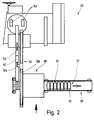
- a suitable lifting conveyor e.g. a Robot with lifting head, sets the blank stack 10 individually or in groups to form a continuous row 17 on a feed conveyor 18. This is as a belt conveyor educated.
- the feed conveyor 18 can be driven in cycles. It transports the blank stack 10 successively in a banderole station 19. In the area of the same the band 11 severed and eliminated. The exempted from the band 11 Blank stacks 10 are transferred to a conveyor, the blank stack 10 for further processing feeds.
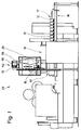
- the banderole station 19 part of a packaging machine 20 for producing Hinged boxes for cigarettes. Feeder 18 and banderole station 19 are in the area of the back of the packaging machine 20 positioned.
- the blank stack 10 is in the banderole station 19 promoted by the feed conveyor 18 on a run, namely on a plate 21.
- the blank stack 10 rests on this during the cutting of the band 11.
- an up and down movable cutting unit 22 positioned above the plate 21 or the blank stack 10 .
- the blade-like knife 23 becomes this Purposes in a horizontal plane relative to the blank stack 10 or moved to the band 11.
- the knife 23 is on a reciprocating knife holder 24 attached, like a sled on a guide rail 25 of the cutting unit 22 is displaceable.
- the elongated knife 23 or a cutting edge 26 of the same is at an acute angle to the direction of movement during the cutting process, ie directed towards the guide rail 25.
- the cutting unit is used to carry out a cutting process 22 through a lifting cylinder 27 to the cutting plane lowered.
- the knife 23 lies directly in one plane below the upper transverse leg 12 the band 11, such that the knife 23 between the upper Cutting the blank stack 10 moves and also with a section occurs between the blanks. It deals a few or just a cut, which lies above the parting plane of the knife 23.
- the knife holder 24 is used to carry out the separating cut moved along the guide rail 25.
- the knife 23 is initially outside the area of the band 11 between the upper blanks until the upright Leg 12 is detected and severed. The knife 23 slides during the cutting movement to the end of the blank stack.
- the preferably over the entire length of the blank stack 10 off-center on this stamp plate 29 has the additional effect that especially the upper ones Cut easily on the side facing the knife 23 to be fanned out. This is the introduction of the knife 23 in the area between the upper blanks.
- the severed sleeve 11 is then removed.
- the band 11 in the region of the leg 12 gripped by a holder.
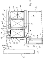
- the blank stack 10 lies with the leg 12 of the sleeve 11 on the contact wall 31 (Fig. 3).
- the contact wall 31 is with holding members for detecting the Banderole 11 provided after cutting. It deals are several suction elements arranged side by side 32. These are positioned on the contact wall 31 that they grasp the separated leg 12 in the upper area.
- the contact wall 31 can be moved up and down in the vertical plane.
- the contact wall 31 is for this purpose with sliding guides 33 on two spaced, upright Guide rods 34 stored. These in turn are above and below with cross struts 35 on a fixed, upright support wall 36 attached.
- a rodless cylinder namely an upright linear cylinder 37 attached.
- a piston that can be moved up and down the same is connected to the slide guides 33.
- By the linear cylinder 37 is accordingly the contact wall 31 and removable.
- the blank stack 10 is now from the banderole station 19 moved out, with the severed band 11 retained or is promoted.
- the blank stack 10 reaches a conveyor without a sleeve 11.
- the blank stack 10 is trapped by the plate 21 from directly onto a platform 39 of a vertical conveyor 40 pushed.
- the one-sided on this vertical conveyor 40 stored platform extends during the recording of the blank stack 10 at the level of the plate 21.
- the transfer of the blank stack 10 from the plate 21 to the vertical conveyor 40 is carried out by a slide unit 41.
- this consists of two upright ones Driving rods 42, 43, which are from a sideways position 8 outside the movement path of the blank stack 10 by opposing transverse movement in between the blank stack 10 on the plate 21 on the one hand and the blank stacks 10 on the feed conveyor 18, on the other hand formed space 44 occur.
- This space 44 has been created in that the feed conveyor 18 after depositing the blank stack 10 on the Plate 21 is driven in the opposite direction, such that a return movement of the row 17 of the blank stack 10 takes place.
- the space 44 Entered driving rods 42, 43 support in a coordinated manner Way the conveying movement of the blank stack 10th from plate 21 to platform 39 during the downward movement the band 11.
- the driver rods 42, 43 are with sliders 45 transverse bars 46 slidable.
- the cross movement the driver rods 42, 43 is effected by cylinder 47.
- the slide unit 41 described so far is for implementation the thrust movement on one in the conveying direction extending linear cylinder 57 attached. This is positioned above the trajectory of the blank stack 10.
- the rods 46 are attached to a support 48, which in turn has a piston of the linear cylinder 57 connected is. Through this the driver rods 42, 43 in the push-off direction of the blank stack 10 with entrainment the same movable.
- the drive rods 42, 43 are out of range the band 11 on the blank stack 10 effective.
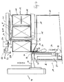
- a side loop 38 is created as a result of the push-off movement through the lower crosspiece 15 of the band. This will completely pulled down once the blank stack deposited on the conveyor or on the platform 39 is (Fig. 6).
- the vertical conveyor 40 assigned a holding member, which a Retains force on the blank stack 10 while the sleeve 11 is pulled off. It is about a pressure roller 58, which is from above on the blank stack 10 is lowered, in the present case in the area the band 11 or the leg 12.
- the pressure roller 58 is mounted on a bracket 59 and by a cylinder (not shown) movable into the pressing position (extended Lines in Figs. 6 and 8).
- the pressure roller is on a pivoted, two-armed lever 60 attached, at its free end the pressure cylinder engages.
- the pressure roller 58 causes the blank stack 10 in unchanged position on platform 39 is fixed while the banderole 11 is pulled down becomes.
- the blank stack 10 is transported away by the vertical conveyor 40.
- a monitoring body namely a light barrier 61. This gives away the stack of blanks 10 free when the banderole 11 is complete has been moved past the light barrier 61.
- the blank stacks 10 are used for further processing fed by the vertical conveyor 40 to a linear conveyor 52. This transports the blank stack 10 at an elevated level Level ("overhead") to the packaging machine 20. Here the blank stacks 10 are passed to blank magazines 53.
- the linear conveyor 52 in the present case consists of a horizontal conveyor track 54, on the blank stack 10 lie on. Lateral guides secure the stack of blanks 10 in this position.
- a floating carrier 55 detects the blank stack 10 on the back and slides it on the conveyor 54.
- the Driver 55 is by an elongated linear cylinder 56 driven. The blank stacks 10 are through the driver 55 from the platform 39 of the vertical conveyor 40 pushed off and directly onto the conveyor track 54 transfer.
Landscapes
- Engineering & Computer Science (AREA)
- Mechanical Engineering (AREA)
- Making Paper Articles (AREA)
- Control And Other Processes For Unpacking Of Materials (AREA)
Description
Die Erfindung betrifft ein Verfahren und eine Vorrichtung zum Transportieren von Zuschnitt-Stapeln sowie zum Durchtrennen und Beseitigen einer den Zuschnitt-Stapel umgebenden Banderole im Bereich einer Banderolen-Station durch ein Messer, wobei das Messer im Bereich eines aufrechten Schenkels der Banderole zwischen Zuschnitten des Zuschnitt-Stapels eingeführt und die Banderole durch Relativbewegung von Messer und Zuschnitt-Stapel entlang dem aufrechten Schenkel durchtrennt wird. Insbesondere geht es um den Transport von Banderolen im Zusammenhang mit einer Verpackungsmaschine, vorzugsweise zu einem Zuschnitt-Magazin der Verpackungsmaschine. Weiterhin betrifft die Erfindung eine Vorrichtung zur Durchführung des Verfahrens.The invention relates to a method and a device for transporting Blank stacking as well as for cutting and removing one the band around the blank stack in the area of a band station through a knife, the knife in the area of an upright leg of the band between blanks of the blank stack and the banderole by relative movement of knives and cut stacks along the upright Thigh is cut. In particular, it is about the Transport of banderoles in connection with a packaging machine, preferably to a blank magazine Packaging machine. The invention further relates to a Device for performing the method.
Zuschnitte für die Fertigung von Verpackungen aus (dünnem) Karton, insbesondere für die Herstellung von Klappschachteln (Hinge-Lid-Packungen) für Zigaretten, werden üblicherweise in einer Kartonagenfabrik vorgefertigt und als Zuschnitt-Stapel angeliefert. Um die Formation der Zuschnitt-Stapel zu sichern, ist es vielfach üblich, die Zuschnitt-Stapel mit einer diese umgebenden streifenförmigen Banderole aus Papier, Folie oder dergleichen zu versehen. Im Bereich der Verpackungsmaschine muß dann die Banderole durchtrennt und beseitigt werden, so daß banderolenfreie Zuschnitt-Stapel der Verpackungsmaschine, insbesondere einem Zuschnitt-Magazin derselben, übergeben werden können.Blanks for the production of packaging from (thin) Cardboard, in particular for the production of hinged boxes (Hinge-lid packs) for cigarettes, are usually in prefabricated in a cardboard box factory and as a blank stack delivered. To secure the formation of the blank stacks, It is common practice to stack the blanks with one of these surrounding strip-shaped band made of paper, film or to provide the like. In the area of the packaging machine must then the band is cut and removed so that banderole-free blank stack of the packaging machine, in particular to a blank magazine of the same can be.
Aus der EP-A-0 100 990 ist es bekannt, die Banderole eines
Stapels durch ein seitlich zwischen einzelne Blätter des
Stapels eintretendes Messer zu durchtrennen, ebenso aus der
EP-A-0 146 391. Die zertrennte Banderole wird jeweils an einer
dem Messer gegenüberliegenden Seite des Stapels von einem
entsprechenden Greiforgan erfaßt und abgezogen. Der Oberbegriff
der Ansprüche 1 und 5 entspricht diesem Stand der Technik.From EP-A-0 100 990 it is known that the band one
Stack by a side between individual sheets of the
To cut the stack of knives entering, also from the
EP-A-0 146 391. The separated band is in each case on one
side of the stack opposite the knife from one
corresponding gripping member detected and deducted. The main topic
of
Die Erfindung befaßt sich mit der Handhabung durch Banderolen umgebenen Zuschnitt-Stapeln im Bereich einer Verpackungsmaschine. Der Erfindung liegt die Aufgabe zugrunde, das Durchtrennen und Beseitigen der Banderolen zu verbessern, insbesondere zu beschleunigen ohne daß die Gefahr der Beschädigung von Zuschnitten besteht.The invention is concerned with handling by banderoles surrounding stack of blanks in the area of a packaging machine. The object of the invention is to cut through and removing the banderoles, in particular to accelerate without the risk of damage to Cutting exists.
Zur Lösung dieser Aufgabe ist das erfindungsgemäße Verfahren dadurch gekennzeichnet, daß das Messer im oberen Bereich des aufrechten Schenkels zwischen oberen Zuschnitten des Zuschnitt-Stapels eingeführt und die Banderole in diesem Bereich durchtrennt wird und daß der Schenkel nach dem Trennen nach unten bis unter den Zuschnitt-Stapel weggezogen wird.The method according to the invention is used to achieve this object characterized in that the knife in the upper region of the Upright leg between the top blanks of the blank stack introduced and cut the banderole in this area and that the thigh after separating down until it is pulled away from under the blank stack.
Die Aufgabe wird weiterhin durch die Vorrichtung gemäß Anspruch 5 gelöst.The object is further achieved by the device according to claim 5.
Zur Beseitigung der durchtrennten Banderole wird diese erfindungsgemäß nach unten weggezogen, und zwar derart, daß nach dem Durchtrennen des aufrechten Schenkels dieser zunächst durch eine aufrechte, auf- und abbewegbare Anlagewand nach unten bewegt und sodann nach dem Abschieben des Zuschnitt-Stapels die Banderole insgesamt durch entsprechende Förderorgane nach unten weggezogen wird.To remove the severed band, this is inventively pulled down, in such a way that after the First cut through the upright leg an upright, up and down movable wall down moved and then after pushing the stack of blanks the Overall banderole down by appropriate funding bodies is pulled away.
Nach dem Durchtrennen der Banderole wird erfindungsgemäß der Zuschnitt-Stapel durch eine besondere Schiebereinheit aus der Banderolen-Station abgeschoben auf einen Abförderer, der die banderolenfreien Zuschnitt-Stapel der Verpackungsmaschine zufördert. Der Abförderer ist vorzugsweise ein Vertikalförderer mit einer Plattform zur Aufnahme je eines Zuschnitt-Stapels. After cutting the banderole according to the invention Cutting stack by a special slide unit from the Banderole station pushed onto a conveyor, which the banderole-free blank stack of the packaging machine promoted. The discharge conveyor is preferably a vertical conveyor with a platform to hold a stack of blanks.
Weitere Merkmale der Erfindung beziehen sich auf Einzelheiten der Banderolen-Station, auf die Organe zum Abziehen und Beseitigen der durchtrennten Banderole, auf das Schneidaggregat sowie auf das Förderorgan zum Abtransportieren des Zuschnitt-Stapels.Further features of the invention relate to details the banderole station, on the organs for peeling and Remove the severed band on the cutting unit as well as on the conveyor for the removal of the Blank stacks.
Weitere Einzelheiten der Erfindung werden nachfolgend anhand eines in den Zeichnungen dargestellten Ausführungsbeispiels der erfindungsgemäßen Vorrichtung näher erläutert. Es zeigt:
- Fig. 1
- eine Verpackungsmaschine in schematischer Darstellung mit einer Banderolen-Station in Rückansicht,
- Fig. 2
- die Banderolen-Station der Verpackungsmaschine gemäß Fig. 1 in schematischem Grundriß,
- Fig. 3
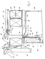
- die Banderolen-Station als Einzelheit in Seitenansicht, bei vergrößertem Maßstab,
- Fig. 4
- eine Darstellung analog Fig. 3 bei veränderter Position von Organen,
- Fig. 5
- eine weitere Darstellung entsprechend Fig. 3 und Fig. 4 während einer Phase der Beseitigung einer durchtrennten Banderole,
- Fig. 6
- eine weitere veränderte Darstellung analog Fig. 3 bis Fig. 5 während des Abschubs eines Zuschnitt-Stapels auf einen Abförderer,
- Fig. 7
- ein Messer-Aggregat in perspektivischer, schematischer Darstellung,
- Fig. 8
- eine Einzelheit der Banderolen-Station im Grundriß.
- Fig. 1
- a packaging machine in a schematic representation with a banderole station in rear view,
- Fig. 2
- the banding station of the packaging machine according to FIG. 1 in a schematic plan view,
- Fig. 3
- the banding station as a detail in side view, on an enlarged scale,
- Fig. 4
- 3 with a changed position of organs,
- Fig. 5
- 3 shows a further illustration corresponding to FIG. 3 and FIG. 4 during a phase of removing a severed band,
- Fig. 6
- 3 shows another modified representation analogous to FIGS. 3 to 5 during the pushing of a stack of blanks onto a removal conveyor,
- Fig. 7
- a knife assembly in a perspective, schematic representation,
- Fig. 8
- a detail of the banderole station in the plan.
Bei den Ausführungsbeispielen der Zeichnungen geht es um
die Handhabung von Zuschnitt-Stapeln 10 aus Zuschnitten für
die Zigaretten-Industrie. Es handelt sich um langgestreckte
Zuschnitte mit der für die Herstellung von Klappschachteln
(Hinge-Lid-Packungen) charakteristischen Kontur. Die Zuschnitte
bestehen aus dünnem Karton.The embodiments of the drawings are about
the handling of
Jeder Zuschnitt-Stapel 10 ist von einer streifenförmigen
Banderole 11 umgeben. Diese ist als endliches, rechteckiges
Schlauchstück ausgebildet mit einander gegenüberliegenden
aufrechten Schenkeln 12, 13 und oberen und unteren
Querstegen 14, 15. Die Banderole 11 ist aus einem endlichen
Materialstreifen gebildet mit einer verklebten Überlappung
16 im Bereich des Schenkels 13. Die Banderole 11 besteht
vorzugsweise aus Papier (Kraftpapier), kann aber auch aus
einer Folie oder einem anderen geeigneten Material
bestehen. Es ist von Vorteil, wenn die Banderole 11 durch
Beschichtung oder andere Maßnahmen weitgehend luftdicht
ausgebildet ist.Each stack of
Die mit einer solchen Banderole 11 versehenen Zuschnitt-Stapel
10 werden beispielsweise auf einer Palette (nicht
gezeigt) angeliefert. Ein geeigneter Hubförderer, z.B. ein
Roboter mit Hubkopf, setzt die Zuschnitt-Stapel 10 einzeln
oder in Gruppen unter Bildung einer fortlaufenden Reihe 17
auf einem Zuförderer 18 ab. Dieser ist als Bandförderer
ausgebildet.The blank stack provided with such a band 11
For example, 10 are on a pallet (not
shown). A suitable lifting conveyor, e.g. a
Robot with lifting head, sets the
Der Zuförderer 18 ist taktweise antreibbar. Er transportiert
die Zuschnitt-Stapel 10 nacheinander in eine Banderolen-Station
19. Im Bereich derselben wird die Banderole 11
durchtrennt und beseitigt. Die von der Banderole 11 befreiten
Zuschnitt-Stapel 10 werden einem Abförderer übergeben,
der die Zuschnitt-Stapel 10 der weiteren Verarbeitung
zuführt. Im vorliegenden Falle ist die Banderolen-Station
19 Teil einer Verpackungsmaschine 20 zum Herstellen von
Klappschachteln für Zigaretten. Zuförderer 18 und Banderolen-Station
19 sind im Bereich der Rückseite der Verpackungsmaschine
20 positioniert. The
In der Banderolen-Station 19 wird der Zuschnitt-Stapel 10
durch den Zuförderer 18 auf eine Auflage gefördert, nämlich
auf eine Platte 21. Auf dieser ruht der Zuschnitt-Stapel 10
während des Durchtrennens der Banderole 11.The
Oberhalb der Platte 21 bzw. des Zuschnitt-Stapels 10 ist
ein auf- und abbewegbares Schneidaggregat 22 positioniert.
Dieses ist mit einer horizontal liegenden Schneidklinge
bzw. einem Messer 23 ausgerüstet zum Durchtrennen der Banderole
11. Das klingenartige Messer 23 wird zu diesem
Zwecke in horizontaler Ebene relativ zum Zuschnitt-Stapel
10 bzw. zur Banderole 11 bewegt.Above the
Das Messer 23 ist an einem hin- und herbewegbaren Messerhalter
24 angebracht, der wie ein Schlitten an einer Führungsschiene
25 des Schneidaggregats 22 verschiebbar ist.
Das langgestreckte Messer 23 bzw. eine Schneidkante 26 desselben
ist unter einem spitzen Winkel zur Bewegungsrichtung
beim Schneidvorgang, also zur Führungsschiene 25 gerichtet.The
Zur Durchführung eines Schneidvorgangs wird das Schneidaggregat
22 durch einen Hubzylinder 27 auf die Schneidebene
abgesenkt. Das Messer 23 liegt dabei in einer Ebene unmittelbar
unterhalb des oberen quergerichteten Schenkels 12
der Banderole 11, derart, daß das Messer 23 zwischen oberen
Zuschnitten des Zuschnitt-Stapels 10 bewegt und auch mit
einem Teilbereich zwischen die Zuschnitte eintritt. Es handelt
sich dabei um wenige oder lediglich einen Zuschnitt,
der oberhalb der Trennebene des Messers 23 liegt.The cutting unit is used to carry out a
Zur Durchführung des Trennschnitts wird der Messerhalter 24
entlang der Führungsschiene 25 verschoben. Das Messer 23
wird dabei zunächst außerhalb des Bereichs der Banderole 11
zwischen oberen Zuschnitten geführt, bis der aufrechte
Schenkel 12 erfaßt und durchtrennt wird. Das Messer 23
gleitet bei der Schneidbewegung bis zum Ende des Zuschnitt-Stapels. The
Durch die Lage der Schnittebene im Bereich des Schenkels 12
entsteht nach Beendigung des Trennschnitts ein Reststeg 28
des Schenkels 12, der mit dem Quersteg 14 verbunden bleibt.
Damit dieses hakenförmige Gebilde zuverlässig beseitigt
wird, ist das Schneidaggregat 22 mit einer Hilfsvorrichtung
versehen. Auf der zum Messer 23 gegenüberliegende Seite des
Zuschnitt-Stapels 10 wird von oben her Druck ausgeübt durch
eine langgestreckte, streifenförmige Stempelplatte 29. Diese
wird mit dem Schneidaggregat 22 von oben her auf den
Zuschnitt-Stapel 10 abgesenkt und durch den Hubzylinder 27
beaufschlagt. Zusammen mit dem Schneidaggregat 22 wird weiterhin
von oben her ein Saugorgan bzw. ein Sauger 30 auf
den Zuschnitt-Stapel 10 abgesenkt. Der Sauger 30 wird in
einem dem Messer 23 zugekehrten Bereich des Querstegs 14
wirksam. Nach Durchführung des Trennschnitts wird der Quersteg
14 unter Mitnahme des Reststegs 28 durch den Sauger 30
angehoben, so daß der Reststeg 28 vom Zuschnitt-Stapel 10
freikommt.Due to the position of the cutting plane in the region of the leg 12
a
Die vorzugsweise über die gesamte Länge des Zuschnitt-Stapels
10 außermittig auf diesem aufliegende Stempelplatte 29
hat den zusätzlichen Effekt, daß insbesondere die oberen
Zuschnitte auf der dem Messer 23 zugekehrten Seite leicht
aufgefächert werden. Dadurch ist die Einführung des Messers
23 in den Bereich zwischen oberen Zuschnitten erleichtert.The preferably over the entire length of the
Nach Durchführung eines Trennschnitts wird das Messer 23
mit dem Messerhalter 24 in die Ausgangsstellung zurück- und
das Schneidaggregat 22 in die obere Ausgangsstellung gemäß
Fig. 4 gefahren.After performing a separating cut, the
Die durchtrennte Banderole 11 wird danach beseitigt. Zu
diesem Zweck wird die Banderole 11 im Bereich des Schenkels
12 durch einen Halter erfaßt. Dieser besteht im vorliegenden
Fall aus einer Anlagewand 31, die in der Ausgangsstellung
zugleich der exakten Positionierung des Zuschnitt-Stapels
10 auf der Platte 21 dient. Der Zuschnitt-Stapel 10
liegt mit dem Schenkel 12 der Banderole 11 an der Anlagewand
31 an (Fig. 3). The severed sleeve 11 is then removed. To
For this purpose, the band 11 in the region of the
Die Anlagewand 31 ist mit Halteorganen zum Erfassen der
Banderole 11 nach dem Durchtrennen versehen. Es handelt
sich dabei um mehrere nebeneinander angeordnete Saugorgane
32. Diese sind so an der Anlagewand 31 positioniert, daß
sie den abgetrennten Schenkel 12 im oberen Bereich erfassen.The
Die Anlagewand 31 ist in vertikaler Ebene auf- und abbewegbar.
Die Anlagewand 31 ist zu diesem Zweck mit Gleitführungen
33 an zwei im Abstand voneinander angeordneten, aufrechten
Führungsstangen 34 gelagert. Diese wiederum sind
oben und unten mit Querstreben 35 an einer feststehenden,
aufrechten Tragwand 36 angebracht. An dieser ist auch ein
kolbenstangenloser Zylinder, nämlich ein aufrechter Linearzylinder
37 befestigt. Ein auf- und abbewegbarer Kolben
desselben ist mit den Gleitführungen 33 verbunden. Durch
den Linearzylinder 37 ist demnach die Anlagewand 31 auf- und
abbewegbar.The
Durch Abwärtsbewegung der Anlagewand 31 aus der oberen Position
gemäß Fig. 3 in die untere gemäß Fig. 4 und Fig. 5
wird der von den Saugorganen 32 gehaltene Schenkel 12 der
Banderole 11 mit abwärts bewegt. Da der Zuschnitt-Stapel 10
unverändert auf dem übrigen Teil der Banderole 11 ruht,
nämlich auf dem unteren Quersteg 15, bildet der Schenkel 12
zunächst eine Schlaufe (Fig. 4).By moving the
Der Zuschnitt-Stapel 10 wird nun aus der Banderolen-Station
19 herausbewegt, wobei die durchtrennte Banderole 11 zurückgehalten
bzw. abgefördert wird. Der Zuschnitt-Stapel 10
gelangt ohne Banderole 11 auf einen Abförderer. Im vorliegenden
Falle wird der Zuschnitt-Stapel 10 von der Platte 21
aus unmittelbar auf eine Plattform 39 eines Vertikalförderers
40 geschoben. Die einseitig an diesem Vertikalförderer
40 gelagerte Plattform erstreckt sich während der Aufnahme
des Zuschnitt-Stapels 10 in Höhe der Platte 21. The
Die Übergabe des Zuschnitt-Stapels 10 von der Platte 21 an
den Vertikalförderer 40 erfolgt durch eine Schiebereinheit
41. Diese besteht im vorliegenden Falle aus zwei aufrechten
Mitnehmerstangen 42, 43, die aus einer Seitwärtsstellung
gemäß Fig. 8 außerhalb der Bewegungsbahn der Zuschnitt-Stapel
10 durch entgegengerichtete Querbewegung in einen zwischen
dem Zuschnitt-Stapel 10 auf der Platte 21 einerseits
und den Zuschnitt-Stapeln 10 auf dem Zuförderer 18 andererseits
gebildeten Zwischenraum 44 eintreten. Dieser Zwischenraum
44 ist dadurch geschaffen worden, daß der Zuförderer
18 nach dem Absetzen des Zuschnitt-Stapels 10 auf der
Platte 21 in entgegengesetzter Richtung angetrieben wird,
derart, daß eine Rückförderbewegung der Reihe 17 der Zuschnitt-Stapel
10 stattfindet. Die in den Zwischenraum 44
eingetretenen Mitnehmerstangen 42, 43 unterstützen in abgestimmter
Weise die Förderbewegung des Zuschnitt-Stapels 10
von der Platte 21 auf die Plattform 39 während der Abwärtsbewegung
der Banderole 11.The transfer of the
Die Mitnehmerstangen 42, 43 sind mit Gleitstücken 45 auf
quergerichteten Stangen 46 verschiebbar. Die Querbewegung
der Mitnehmerstangen 42, 43 wird durch Zylinder 47 bewirkt.The
Die insoweit beschriebene Schiebereinheit 41 ist zur Durchführung
der Schubbewegung an einem sich in Förderrichtung
erstreckenden Linearzylinder 57 angebracht. Dieser ist
oberhalb der Bewegungsbahn der Zuschnitt-Stapel 10 positioniert.
Die Stangen 46 sind an einem Träger 48 angebracht,
der seinerseits mit einem Kolben des Linearzylinders 57
verbunden ist. Durch diesen sind die Mitnehmerstangen 42,
43 in Abschubrichtung des Zuschnitt-Stapels 10 unter Mitnahme
desselben bewegbar.The
Die Mitnehmerstangen 42, 43 werden außerhalb des Bereichs
der Banderole 11 am Zuschnitt-Stapel 10 wirksam. Bei der
Abschubbewegung entsteht dadurch eine Seitenschlaufe 38
durch den unteren Quersteg 15 der Banderole. Diese wird
vollständig nach unten weggezogen, sobald der Zuschnitt-Stapel
auf dem Abförderer bzw. auf der Plattform 39 abgesetzt
ist (Fig. 6).The
Zum vollständigen Abtransport der durchtrennten Banderole
11 in Abwärtsrichtung werden weitere Zugorgane wirksam. Es
handelt sich dabei um ein Zugwalzenpaar mit einer ortsfesten,
größeren Zugwalze 49 und einer mitlaufenden Gegenwalze
50. Letztere ist an der Anlagewand 31 angebracht,
unterhalb der Saugorgane 32. Die Banderole 11 bzw. deren
Schenkel 12 liegt nach dem Abtrennen an der Gegenwalze 50
an. Durch die Absenkbewegung in die Position gemäß Fig. 4
gelangt die Gegenwalze 50 in eine Position gegenüber der
Zugwalze 49. Durch die gemeinsame Wirkung des Walzenpaares
49/50 wird dann die Banderole 11 insgesamt nach unten
gefördert.For the complete removal of the severed band
11 in the downward direction, other traction elements become effective. It
is a pair of pull rollers with a fixed,
Larger pull
Die schließlich vollständig von dem Zuschnitt-Stapel 10 abgezogene
Banderole 11 gelangt in einen Sammelbehälter 51
unterhalb der Platte 21.The one that was finally completely removed from the
Trotz der Wirkung des Saugers 30 ist nicht immer auszuschließen,
daß der obere Quersteg 14 nach dem Trennschnitt
mit dem Reststeg 28 in die Ausgangsstellung zurückfällt
(Fig. 6, strichpunktierte Linie). Bei dem vollständigen Abzug
der Banderole 11 muß sichergestellt werden, daß durch
den Reststeg 28 obere Zuschnitte des Zuschnitt-Stapels 10
nicht mit abgezogen werden. Zu diesem Zweck ist dem Vertikalförderer
40 ein Halteorgan zugeordnet, welches eine
Rückhaltekraft auf den Zuschnitt-Stapel 10 ausübt, während
die Banderole 11 abgezogen wird. Es handelt sich dabei um
eine Andrückrolle 58, die von oben her auf den Zuschnitt-Stapel
10 abgesenkt wird, im vorliegenden Fall im Bereich
der Banderole 11 bzw. des Schenkels 12. Die Andrückrolle 58
ist an einer Halterung 59 gelagert und durch einen Zylinder
(nicht gezeigt) in die Andrückstellung bewegbar (ausgezogene
Linien in Fig. 6 und 8). Die Andrückrolle ist dabei an
einem schwenkbar gelagerten, zweiarmigen Hebel 60 angebracht,
an dessen freiem Ende der Druckmittelzylinder angreift.
Die Andrückrolle 58 bewirkt, daß der Zuschnitt-Stapel
10 in unveränderter Position auf der Plattform 39
fixiert ist, während die Banderole 11 nach unten abgezogen
wird.Despite the action of the
Erst nach vollständigem Beseitigen der Banderole 11 wird
der Zuschnitt-Stapel 10 durch den Vertikalförderer 40 abtransportiert.
Zu diesem Zweck ist unterhalb der Banderolen-Station
19 ein Überwachungsorgan angebracht, nämlich
eine Lichtschranke 61. Diese gibt den Abtransport des Zuschnitt-Stapels
10 frei, wenn die Banderole 11 vollständig
an der Lichtschranke 61 vorbeibewegt worden ist.Only after the banderole 11 has been completely removed
the
Die Zuschnitt-Stapel 10 werden für die weitere Verarbeitung
durch den Vertikalförderer 40 einem Linearförderer 52 zugeführt.
Dieser transportiert die Zuschnitt-Stapel 10 auf erhöhtem
Niveau ("überkopf") zur Verpackungsmaschine 20. Hier
werden die Zuschnitt-Stapel 10 Zuschnitt-Magazinen 53 übergeben.The
Der Linearförderer 52 besteht im vorliegenden Falle aus einer
horizontalen Förderbahn 54, auf der Zuschnitt-Stapel 10
aufliegen. Seitliche Führungen sichern die Zuschnitt-Stapel
10 in dieser Position. Ein hin- und herbewegbarer Mitnehmer
55 erfaßt den Zuschnitt-Stapel 10 jeweils an der Rückseite
und transportiert ihn gleitend auf der Förderbahn 54. Der
Mitnehmer 55 wird durch einen langgestreckten Linearzylinder
56 angetrieben. Die Zuschnitt-Stapel 10 werden durch
den Mitnehmer 55 von der Plattform 39 des Vertikalförderers
40 abgeschoben und unmittelbar auf die Förderbahn 54
übertragen.The
Claims (10)
- Process for transporting stacks (10) of blanks and for severing and removing a wrapping band (11) surrounding the stack (10) of blanks in the area of a wrapping station (19) by means of a knife (23), the knife (23) being inserted between blanks of the stack (10) of blanks in the area of an upright limb (12) of the wrapping band (11), and the wrapping band (11) being severed by means of a relative movement of knife (23) and stack (10) of blanks along the upright limb (12), characterized in that the knife (23) is inserted between upper blanks of the stack (10) of blanks in the upper region of the upright limb (12), and the wrapping band (11) is severed in this region, and in that, following the severing, the limb (12) is drawn away downwards until it is below the stack (10) of blanks.
- Process according to Claim 1, characterized in that in an area located opposite the knife (23), pressure is exerted on the upper side of the stack (10) of blanks and/or on the upper transverse web (14) of the wrapping band (11) in such a way that the area, facing the knife (23), of the upper blanks, and/or of the upper transverse web (14) is lifted slightly.
- Process according to Claim 1 or 2, characterized in that a giving force is exerted on the upper transverse web (14) of the wrapping band or on that free area of the blanks facing the knife (23), in particular by sucking up the transverse web (14) and/or the upper blank.
- Process according to Claim 1 or one of the other claims, characterized in that the stack (10) of blanks, free of wrapping bands, is transported away by a discharge conveyor, the wrapping band (11) as a whole being drawn away downwards.
- Device for carrying out the process according to one of Claims 1 to 4, having a knife (23) that extends in the horizontal plane, projects on one side and enters between blanks of the stack (10) of blanks, characterized in that the knife (23) can be moved in a plane between upper blanks, in the area of the upright limb (12) and relative to the non-moving stack (10) of blanks and in order to sever the wrapping band (11), and in that a holding element (32) which seizes the severed limb (12) and draws it away downwards is provided.
- Device according to Claim 5, characterized by a bearing wall (31) for positioning the stack (10) of blanks in the wrapping station (19) on a plate (21), the bearing wall (31) having the holding elements for seizing the limb (12) of the wrapping band (11), in particular suction elements (32), and being able to move up and down in the vertical plane in order to draw the limb (12) or the wrapping band (11) away.
- Device according to Claim 5 or one of the other claims, characterized in that the wrapping band (11) can be drawn away downwards by means of additional drawing elements, in particular by a pair of drawing rolls with fixed drawing roll (49) and mating roll (50) arranged on the bearing wall (31).
- Device according to Claim 5 or one of the other claims, characterized in that the wrapping band (11) or an upper, horizontal transverse web (14) and/or upper blanks of the stack (10) of blanks can be lifted slightly to insert the knife (23), in particular by means of a sucker (30) and/or by means of a pressure element/plunger plate (29) acting on the wrapping band (11) or on the stack (10) of blanks.
- Device according to Claim 5 or one of the other claims, characterized in that the stack (10) of blanks, after the severing of the wrapping band (11), can be pushed away out of the wrapping station (19) by means of a pusher element or a pusher unit (41) engaging on the stack (10) of blanks on that side located opposite the severed limb (12), being preferably pushed away directly onto a driver or a platform (39) of a (vertical) conveyor (40) for the transporting away of the blanks.
- Device according to Claim 9, characterized in that the pusher unit (41) for pushing away the stack (10) of blanks preferably comprises two upright driver rods (42, 43), which can be moved by means of a sideways movement into the movement path of the stack (10) of blanks and can be moved out of the latter as well as additionally in the conveying direction of the stacks (10) of blanks.
Applications Claiming Priority (2)
| Application Number | Priority Date | Filing Date | Title |
|---|---|---|---|
| DE4436330 | 1994-10-11 | ||
| DE19944436330 DE4436330A1 (en) | 1994-10-11 | 1994-10-11 | Method and device for handling stacked blanks with banderoles |
Publications (2)
| Publication Number | Publication Date |
|---|---|
| EP0706946A1 EP0706946A1 (en) | 1996-04-17 |
| EP0706946B1 true EP0706946B1 (en) | 1998-07-29 |
Family
ID=6530499
Family Applications (1)
| Application Number | Title | Priority Date | Filing Date |
|---|---|---|---|
| EP19950115106 Expired - Lifetime EP0706946B1 (en) | 1994-10-11 | 1995-09-26 | Method and device for handling stacks of blanks with strapping band |
Country Status (4)
| Country | Link |
|---|---|
| US (1) | US5758362A (en) |
| EP (1) | EP0706946B1 (en) |
| JP (1) | JP3261024B2 (en) |
| DE (2) | DE4436330A1 (en) |
Cited By (1)
| Publication number | Priority date | Publication date | Assignee | Title |
|---|---|---|---|---|
| WO2010003483A1 (en) | 2008-07-10 | 2010-01-14 | Focke & Co. (Gmbh & Co. Kg) | Method and device for cutting through a banderole encompassing a stack of blanks |
Families Citing this family (21)
| Publication number | Priority date | Publication date | Assignee | Title |
|---|---|---|---|---|
| DE19650689A1 (en) | 1996-12-06 | 1998-06-10 | Focke & Co | Device for handling stacks of blanks |
| DE19728515A1 (en) * | 1997-07-04 | 1999-01-07 | Focke & Co | Method and device for manufacturing folding boxes for cigarettes |
| JPH11138665A (en) * | 1997-11-12 | 1999-05-25 | Fuji Photo Film Co Ltd | Method and apparatus for peeling label |
| DE69918199T2 (en) * | 1998-01-30 | 2005-07-07 | Nippon Paper Industries Co. Ltd. | Method and apparatus for opening a package using interconnected parts thereof |
| IT1304036B1 (en) * | 1998-07-15 | 2001-03-02 | Gd Spa | METHOD AND DEVICE FOR THE FEEDING OF WRAPS OF WRAPPING MATERIAL IN A PACKAGING MACHINE. |
| EP0980831B1 (en) * | 1998-08-20 | 2003-05-28 | Sinomec Ag | Method and apparatus for removing wrappings from articles |
| JP4059487B2 (en) * | 2002-11-29 | 2008-03-12 | ジェイティエンジニアリング株式会社 | Parts supply device |
| CA2416241A1 (en) * | 2003-01-14 | 2004-07-14 | Labatt Brewing Company Limited | Bottom saw blade height adjustment |
| US7174695B2 (en) * | 2003-06-04 | 2007-02-13 | Porter Dan C | De-packaging machine |
| DE102004007488A1 (en) * | 2004-02-13 | 2005-09-15 | Heino Ilsemann Gmbh | Device and method for unpacking banded objects |
| US7341416B1 (en) * | 2004-12-30 | 2008-03-11 | Rubtsov Yuriy N | Machine and method to feed filled bags, open the bags, empty the bags, and dispose of the empty bags |
| PL211905B1 (en) * | 2006-03-17 | 2012-07-31 | Int Tobacco Machinery Poland | Method and device for removal of packaging of plastic coating |
| US7963086B2 (en) * | 2007-11-06 | 2011-06-21 | Porter Technologies, Llc | Package unbundling system |
| US11186399B2 (en) * | 2013-03-12 | 2021-11-30 | Robotica, Inc. | Automated container cutting apparatus |
| CN105460307B (en) * | 2015-12-21 | 2017-10-10 | 汕头市美宝制药有限公司 | A kind of sterile automatic tube feeding machine of ointment |
| PT3214004T (en) * | 2016-03-03 | 2019-01-10 | Freixenet S A | Method of unwrapping a palletised load and device for carrying out said method |
| CN105711910B (en) * | 2016-03-25 | 2018-05-18 | 云南昆船电子设备有限公司 | Cigarette bag based on robot packs square auxiliary material automatic charging baric systerm |
| JP6922451B2 (en) * | 2017-06-08 | 2021-08-18 | コニカミノルタ株式会社 | Paper feed device |
| CN111056099A (en) * | 2019-12-24 | 2020-04-24 | 上海西派埃智能科技有限公司 | Automatic unsealing device for bread bag |
| US11981507B2 (en) | 2020-06-03 | 2024-05-14 | Robotica, Inc. | Tote handling system with tote handler and method of using same |
| US11981023B2 (en) | 2020-01-17 | 2024-05-14 | Robotica, Inc. | Tote handling system with integrated hand and method of using same |
Family Cites Families (19)
| Publication number | Priority date | Publication date | Assignee | Title |
|---|---|---|---|---|
| CH625756A5 (en) * | 1978-03-02 | 1981-10-15 | Born Ag Peter | |
| US4390313A (en) * | 1980-03-27 | 1983-06-28 | Hoehn John Walter | Method and apparatus for depacking articles |
| DE3229765A1 (en) | 1982-08-10 | 1984-02-16 | GAO Gesellschaft für Automation und Organisation mbH, 8000 München | DEVICE FOR REMOVING A BANDEROLE FROM A BUNCH OF SHEETS |
| GB8333856D0 (en) | 1983-12-20 | 1984-02-01 | Delco Prod Overseas | Sheet sorting apparatus |
| DE3443362A1 (en) * | 1984-11-28 | 1986-05-28 | Kodak Ag, 7000 Stuttgart | COPIER |
| NL8500606A (en) * | 1985-03-04 | 1986-10-01 | Endra Bv | METHOD AND DEVICE FOR CUTTING AND REMOVING A WIRE OR STRAP STRING ELEMENT ATTACHED TO AN OBJECT OR STACK OF OBJECTS. |
| NL8601747A (en) * | 1986-07-04 | 1988-02-01 | Speciaalmachinefabriek J H Van | DEVICE FOR REMOVING THE BELT FROM A LOADED PALLET. |
| FR2633587B1 (en) * | 1988-06-29 | 1991-03-29 | Vega Automation | METHOD AND DEVICE FOR BREAKING AND REMOVING A LINK SURROUNDING A PACKAGE. CUT FEEDING METHOD AND APPARATUS USING THE SAME |
| JP2746994B2 (en) * | 1989-03-30 | 1998-05-06 | 株式会社東芝 | Paper strip strip remover |
| US5190430A (en) * | 1989-08-01 | 1993-03-02 | G. D. S.P.A. | Apparatus for feeding packaging machines with stacks of sheet material |
| IT1244236B (en) * | 1990-09-11 | 1994-07-08 | Gd Spa | DEVICE FOR THE AUTOMATIC FEEDING OF STACKS OF BLANKS TO A MACHINE USING FOR EXAMPLE A WRAPPING MACHINE. |
| US5101793A (en) * | 1990-10-30 | 1992-04-07 | Sample Larry A | Manually adjustable override for fuel injection regulators |
| DE4105149A1 (en) * | 1991-02-20 | 1992-08-27 | Truetzschler & Co | METHOD AND DEVICE FOR REMOVING THE PACKAGING (EMBALLAGE), e.g. SAECKE OR THE LIKE OF TEXTILE RAW MATERIAL BALLS, ESPECIALLY COTTON AND CHEMICAL FIBER BALES |
| JPH05269693A (en) * | 1992-03-23 | 1993-10-19 | Ishii Kogyo Kk | Band cutting device |
| US5282346A (en) * | 1992-05-14 | 1994-02-01 | Oji Seitai Kaisha, Ltd. | Unwrapping apparatus with swing arms and grippers |
| IT1258130B (en) * | 1992-12-24 | 1996-02-20 | Comas Spa | AUTOMATIC MACHINE FOR CUTTING AND REMOVING THE ENVELOPE OF A UNABALLA, IN PARTICULAR OF A TOBACCO BALL. |
| DE4301169A1 (en) * | 1993-01-20 | 1994-07-21 | Focke & Co | Method and device for handling stacked blanks with banderole |
| US5419095A (en) * | 1993-03-09 | 1995-05-30 | Dyco | Bag stripping apparatus |
| EP0639663B1 (en) * | 1993-08-12 | 1998-09-30 | Maschinenfabrik Rieter Ag | Method and apparatus for the treatment of foreign bodies during the ball opening |
-
1994
- 1994-10-11 DE DE19944436330 patent/DE4436330A1/en not_active Withdrawn
-
1995
- 1995-09-26 DE DE59502963T patent/DE59502963D1/en not_active Expired - Lifetime
- 1995-09-26 EP EP19950115106 patent/EP0706946B1/en not_active Expired - Lifetime
- 1995-10-10 US US08/540,486 patent/US5758362A/en not_active Expired - Fee Related
- 1995-10-11 JP JP26333995A patent/JP3261024B2/en not_active Expired - Fee Related
Cited By (2)
| Publication number | Priority date | Publication date | Assignee | Title |
|---|---|---|---|---|
| WO2010003483A1 (en) | 2008-07-10 | 2010-01-14 | Focke & Co. (Gmbh & Co. Kg) | Method and device for cutting through a banderole encompassing a stack of blanks |
| DE102008032368A1 (en) | 2008-07-10 | 2010-01-14 | Focke & Co.(Gmbh & Co. Kg) | Method and apparatus for severing a band surrounding a blank stack |
Also Published As
| Publication number | Publication date |
|---|---|
| DE59502963D1 (en) | 1998-09-03 |
| JPH08175527A (en) | 1996-07-09 |
| EP0706946A1 (en) | 1996-04-17 |
| US5758362A (en) | 1998-06-02 |
| DE4436330A1 (en) | 1996-04-18 |
| JP3261024B2 (en) | 2002-02-25 |
Similar Documents
| Publication | Publication Date | Title |
|---|---|---|
| EP0706946B1 (en) | Method and device for handling stacks of blanks with strapping band | |
| EP0421148B1 (en) | Device and method for transporting and stacking of die-cuts for the production of (cigarette-) packages | |
| EP2296983B1 (en) | Method and device for cutting through a banderole encompassing a stack of blanks | |
| EP0560112B1 (en) | Device for feeding intermediate layers to a stack | |
| EP2197745B1 (en) | Method for handling pieces or grains of tobacco articles, especially chewing tobacco or snus | |
| EP0444547B1 (en) | Method and device for conveying closing strips in order to transfer them to packages | |
| EP0258597A2 (en) | Device for feeding blanks to a packing machine | |
| EP0031515A1 (en) | Apparatus for producing packaging blanks by separation from a continuously moving web | |
| EP0149076B1 (en) | Method and device for applying drinking straws to beverage containers, especially to beverage bags | |
| DE69104553T2 (en) | Device for producing cartons from flat, sleeve-like blanks. | |
| EP0607626B1 (en) | Method and apparatus for handling strapped piles of blanks | |
| EP0612661A1 (en) | Apparatus for manufacturing a transport package | |
| WO2022096456A1 (en) | Multipack for cigarette industry products, and method for producing same | |
| EP0716637B1 (en) | Process and device for forming and labelling packaging containers | |
| EP0663356A1 (en) | Device for separating packages | |
| DE102008029766B4 (en) | Device for packaging flat articles | |
| DE4220026A1 (en) | Method for removing stacks from a pallet in packing machines | |
| DE3804946A1 (en) | METHOD AND DEVICE FOR SEPARATING LEVEL PARTS | |
| DE4416540C1 (en) | Method of wrapping blocks of insulating material | |
| EP0562432B1 (en) | Method and device for unloading sheetpackages from a pallet or the like | |
| WO2012084073A1 (en) | Method for removing film from packaging units and film-removal station | |
| WO2023280704A1 (en) | Method and device for handling packaging material blanks | |
| EP0888969A1 (en) | Method and apparatus for making hinged-lid boxes for cigarettes | |
| DE3603484A1 (en) | Method and device for the ordered transporting away of piles of paper | |
| DE102022113839A1 (en) | Method and device for attaching tear strips to a continuous web of material |
Legal Events
| Date | Code | Title | Description |
|---|---|---|---|
| PUAI | Public reference made under article 153(3) epc to a published international application that has entered the european phase |
Free format text: ORIGINAL CODE: 0009012 |
|
| AK | Designated contracting states |
Kind code of ref document: A1 Designated state(s): DE GB IT |
|
| 17P | Request for examination filed |
Effective date: 19960601 |
|
| 17Q | First examination report despatched |
Effective date: 19970327 |
|
| GRAG | Despatch of communication of intention to grant |
Free format text: ORIGINAL CODE: EPIDOS AGRA |
|
| GRAG | Despatch of communication of intention to grant |
Free format text: ORIGINAL CODE: EPIDOS AGRA |
|
| GRAH | Despatch of communication of intention to grant a patent |
Free format text: ORIGINAL CODE: EPIDOS IGRA |
|
| GRAH | Despatch of communication of intention to grant a patent |
Free format text: ORIGINAL CODE: EPIDOS IGRA |
|
| GRAA | (expected) grant |
Free format text: ORIGINAL CODE: 0009210 |
|
| AK | Designated contracting states |
Kind code of ref document: B1 Designated state(s): DE GB IT |
|
| GBT | Gb: translation of ep patent filed (gb section 77(6)(a)/1977) |
Effective date: 19980729 |
|
| REF | Corresponds to: |
Ref document number: 59502963 Country of ref document: DE Date of ref document: 19980903 |
|
| PLBE | No opposition filed within time limit |
Free format text: ORIGINAL CODE: 0009261 |
|
| STAA | Information on the status of an ep patent application or granted ep patent |
Free format text: STATUS: NO OPPOSITION FILED WITHIN TIME LIMIT |
|
| 26N | No opposition filed | ||
| REG | Reference to a national code |
Ref country code: GB Ref legal event code: IF02 |
|
| PGFP | Annual fee paid to national office [announced via postgrant information from national office to epo] |
Ref country code: GB Payment date: 20070926 Year of fee payment: 13 |
|
| PGFP | Annual fee paid to national office [announced via postgrant information from national office to epo] |
Ref country code: IT Payment date: 20070926 Year of fee payment: 13 |
|
| GBPC | Gb: european patent ceased through non-payment of renewal fee |
Effective date: 20080926 |
|
| PG25 | Lapsed in a contracting state [announced via postgrant information from national office to epo] |
Ref country code: IT Free format text: LAPSE BECAUSE OF NON-PAYMENT OF DUE FEES Effective date: 20080926 |
|
| PG25 | Lapsed in a contracting state [announced via postgrant information from national office to epo] |
Ref country code: GB Free format text: LAPSE BECAUSE OF NON-PAYMENT OF DUE FEES Effective date: 20080926 |
|
| PGFP | Annual fee paid to national office [announced via postgrant information from national office to epo] |
Ref country code: DE Payment date: 20090924 Year of fee payment: 15 |
|
| REG | Reference to a national code |
Ref country code: DE Ref legal event code: R119 Ref document number: 59502963 Country of ref document: DE Effective date: 20110401 |
|
| PG25 | Lapsed in a contracting state [announced via postgrant information from national office to epo] |
Ref country code: DE Free format text: LAPSE BECAUSE OF NON-PAYMENT OF DUE FEES Effective date: 20110401 |