EP0706748B1 - Dispositif d'affichage couleur electroluminescent a couches minces - Google Patents
Dispositif d'affichage couleur electroluminescent a couches minces Download PDFInfo
- Publication number
- EP0706748B1 EP0706748B1 EP94917429A EP94917429A EP0706748B1 EP 0706748 B1 EP0706748 B1 EP 0706748B1 EP 94917429 A EP94917429 A EP 94917429A EP 94917429 A EP94917429 A EP 94917429A EP 0706748 B1 EP0706748 B1 EP 0706748B1
- Authority
- EP
- European Patent Office
- Prior art keywords
- layer
- electroluminescent display
- metal
- display panel
- light absorbing
- Prior art date
- Legal status (The legal status is an assumption and is not a legal conclusion. Google has not performed a legal analysis and makes no representation as to the accuracy of the status listed.)
- Expired - Lifetime
Links
Images


Classifications
-
- H—ELECTRICITY
- H05—ELECTRIC TECHNIQUES NOT OTHERWISE PROVIDED FOR
- H05B—ELECTRIC HEATING; ELECTRIC LIGHT SOURCES NOT OTHERWISE PROVIDED FOR; CIRCUIT ARRANGEMENTS FOR ELECTRIC LIGHT SOURCES, IN GENERAL
- H05B33/00—Electroluminescent light sources
- H05B33/02—Details
-
- H—ELECTRICITY
- H05—ELECTRIC TECHNIQUES NOT OTHERWISE PROVIDED FOR
- H05B—ELECTRIC HEATING; ELECTRIC LIGHT SOURCES NOT OTHERWISE PROVIDED FOR; CIRCUIT ARRANGEMENTS FOR ELECTRIC LIGHT SOURCES, IN GENERAL
- H05B33/00—Electroluminescent light sources
- H05B33/12—Light sources with substantially two-dimensional radiating surfaces
- H05B33/22—Light sources with substantially two-dimensional radiating surfaces characterised by the chemical or physical composition or the arrangement of auxiliary dielectric or reflective layers
-
- H—ELECTRICITY
- H05—ELECTRIC TECHNIQUES NOT OTHERWISE PROVIDED FOR
- H05B—ELECTRIC HEATING; ELECTRIC LIGHT SOURCES NOT OTHERWISE PROVIDED FOR; CIRCUIT ARRANGEMENTS FOR ELECTRIC LIGHT SOURCES, IN GENERAL
- H05B33/00—Electroluminescent light sources
- H05B33/12—Light sources with substantially two-dimensional radiating surfaces
- H05B33/26—Light sources with substantially two-dimensional radiating surfaces characterised by the composition or arrangement of the conductive material used as an electrode
- H05B33/28—Light sources with substantially two-dimensional radiating surfaces characterised by the composition or arrangement of the conductive material used as an electrode of translucent electrodes
-
- Y—GENERAL TAGGING OF NEW TECHNOLOGICAL DEVELOPMENTS; GENERAL TAGGING OF CROSS-SECTIONAL TECHNOLOGIES SPANNING OVER SEVERAL SECTIONS OF THE IPC; TECHNICAL SUBJECTS COVERED BY FORMER USPC CROSS-REFERENCE ART COLLECTIONS [XRACs] AND DIGESTS
- Y10—TECHNICAL SUBJECTS COVERED BY FORMER USPC
- Y10S—TECHNICAL SUBJECTS COVERED BY FORMER USPC CROSS-REFERENCE ART COLLECTIONS [XRACs] AND DIGESTS
- Y10S428/00—Stock material or miscellaneous articles
- Y10S428/917—Electroluminescent
Definitions
- This invention relates to electroluminescent displays and more particularly to color electroluminescent displays.
- Thin film electroluminescent (TFEL) display panels offer several advantages over older display technologies such as cathode ray tubes (CRTs) and liquid crystal displays (LCDs). Compared with CRTs, TFELs display panels require less power, provide a larger viewing angle, and are much thinner. Compared with LCDs, TFEL display panels have a larger viewing angle, do not require auxiliary lighting, and can have a larger display area.
- CRTs cathode ray tubes
- LCDs liquid crystal displays
- Fig. 1 shows a prior art monochrome TFEL display panel.
- the monochrome TFEL display has a glass panel 11, a plurality of transparent electrodes 12, a first layer of a dielectric 13, a phosphor layer 14, a second dielectric layer 15, and a plurality of metal electrodes 16 perpendicular to the transparent electrodes 12.
- the transparent electrodes 12 are typically indium-tin oxide (ITO) and the metal electrodes 16 are typically Al.
- ITO indium-tin oxide
- the dielectric layers 13,15 act as capacitors to protect the phosphor layer 14 from excessive currents.
- the phosphor layer 14 typically comprises ZnS doped with Mn in a monochrome TFEL display. Electrons entering the phosphor layer 14 excite the Mn causing the Mn to emit photons. The photons pass through the first dielectric layer 13, the transparent electrodes 12, and the glass panel 11 to form a visible image.
- Color TFEL panels are also known in the art.
- U.S. patent 4,717,606 issued January 6, 1988 and assigned to Rockwell International Corporation discloses ion implanting various dopants into a ZnS host to create a multi-color display.
- RGB red-green-blue
- TFEL displays are satisfactory for some applications where there is low ambient lighting, more advanced applications require brighter, higher contrast displays, larger displays, and sunlight viewable color displays.
- RGB red-green-blue
- current color TFEL displays are satisfactory for some applications where there is low ambient lighting, more advanced applications require brighter, higher contrast displays, larger displays, and sunlight viewable color displays.
- In an effort to overcome these problems there is a great deal of ongoing industry research and development to improve TFEL phosphors and thus increase display brightness, especially blue phosphor. In the mean time other display improvements will continue to increase the brightness and contrast of multi-color TFEL displays.
- An object of the present invention is to provide a color TFEL display having improved brightness and improved contrast.
- Another object of the present invention is to provide a more easily manufactured color TFEL display.
- an enhanced brightness color TFEL display includes a phosphor layer of ZnS having various activators and co-activators implanted therein, and a layer of light absorbing dark material is included within the color TFEL having a low ohm metal assist structure in electrical contact over each transparent electrode.
- the combination of the low ohm metal assist structure for each transparent electrode and implantation of the phosphor activators and co-activators in the ZnS host material provides an enhanced brightness, easily manufactured multi-color TFEL display.
- the addition of a light absorbing dark layer to the multi-color TFEL display improves the contrast of the display.
- the present invention provides a multi-color TFEL display panel which is comfortably viewable in direct sunlight.
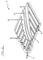
- a multi-color thin film electroluminescent (TFEL) display 20 includes a plurality of transparent electrodes 22 deposited on a glass panel 23.
- Each of the transparent electrodes 22 includes a low resistance metal assist structure 24 in electrical contact with a portion of the transparent electrode 22 to decrease electrode resistance. Reducing the resistance of each transparent electrode allows the drive electronics to increase the refresh rate, and hence realize a brighter display since brightness is directly proportional to the refresh rate of the display.
- the multi-color TFEL also includes a first dielectric layer 26, a phoshor layer 28, a second dielectric layer 30, a layer of light absorbing dark material 31, and segmented metal electrodes 32 which run orthogonal to the transparent electrodes 22.
- Each segmented electrode includes sub-electrodes 32a,32b,32c (e.g., three for a RGB display) each independently addressable for selecting the desired color at a particular pixel site.
- Each metal assist structure 24 extends the entire length of its corresponding transparent electrode 22 and can include one or more layers of an electrically conductive metal compatible with the transparent electrode 22 and other structures within the display 20.
- the structure should cover only a small portion of the transparent electrode 22.
- the metal assist structure 24 can cover about 10% or less of the transparent electrode 22. Therefore, for a typical transparent electrode 22 that is about 250 ⁇ m (10 mils) wide, the metal assist structure 24 should overlap the transparent electrode by about 25 ⁇ m (1 mill) or less. Overlaps as small as about 6 ⁇ m (0.25 mils) to about 13 ⁇ m (0.5 mils) are desirable.
- the metal assist structure 24 should overlap the transparent electrode 22 as little as possible, the metal assist structure should be as wide as practical to decrease electrical resistance. For example, a metal assist structure 24 that is about 50 ⁇ m (2 mils) to about 75 ⁇ m (3 mils) wide may be desirable. These two design parameters can be satisfied by allowing the metal assist structure 24 to overlap the glass panel 23 as well as the transparent electrode 22.
- the thickness of the metal assist structure 24 should be equal to or less than the thickness of the first dielectric layer 26 to ensure that the first dielectric layer 26 adequately covers the transparent electrode 22 and metal assist structure 24.
- the metal assist structure 24 can be less than about 250 nm thick.
- the metal assist structure will be less than about 200 nm thick, such as between about 150 nm and about 200 nm thick.
- the layer of light absorbing dark material 31 reduces the amount of ambient light reflected by the aluminum rear electrodes 32, and hence improves the display's contrast.
- the dark layer 31 should be in direct contact with the aluminum rear electrodes 32 and have a resistivity large enough to reduce electrical crosstalk between the rear electrodes 32, which is a result of leakage currents between the rear electrodes.
- the dark material should have a resistivity at least 10 8 ohms/cm.
- the layer of dark material 31 should also have a dielectric constant which is at least equal to or greater than the dielectric constant of the second dielectric 30, and preferably have a dielectric constant greater than seven. In order to provide a diffuse reflectance of less than 0.5%, the dark material should also have a light absorption coefficient of about 10 5 /cm.
- Candidate materials for the layer of dark material 31 include Ge, CdTe, CdSe, Sb 2 S 3 , GeN and PrMnO 3 .
- the use of Ge has been marginally successfully and a more appropriate material may be GeN due to its higher breakdown threshold.
- PrMnO 3 in the proper composition has resistivity of greater than 10 8 ohms/cm, a dielectric constant between 200 and 300, and a light absorption coefficient of greater than 10 5 /cm at 500 nm. This combination of properties makes PrMnO 3 the preferred black layer material.
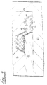
- Pr-Mn oxide films can be deposited using RF sputtering techniques with substrate temperatures ranging between 200-350 deg C in an Ar or Ar+O 2 atmosphere. Fig.
- PrMnO 3 is an illustration of how the resistivity and dielectric constant of the PrMnO 3 can be tailored for the particular application by varying the composition of the Pr-Mn oxide film. Note that the extremely high dielectric constant achievable with PrMnO 3 as shown along a line 35, implies that PrMnO 3 can be utilized without having to significantly increase the display's threshold voltage.
- a preferred embodiment of the metal assist structure 24 is a sandwich of an adhesion layer 40, a first refractory metal layer 42, a primary conductor layer 44, and a second refractory metal layer 46.
- the adhesion layer 40 promotes the bonding of the metal assist structure 24 to the glass panel 23 and the transparent electrode 22. It can include any electrically conductive metal or alloy that can bond to the glass panel 23, transparent electrode 22, and first refractory metal layer 42 without forming stresses that may cause the adhesion layer 40 or any of the other layers to peel away from these structures.
- Suitable metals include Cr, V, and Ti. Cr is preferred because it evaporates easily and provides good adhesion.
- the adhesion layer 40 will be only as thick as needed to form a stable bond between the structures it contacts.
- the adhesion layer 40 can be about 10 nm to about 20 nm thick. If the first refractory metal layer 42 can form stable, low stress bonds with the glass panel 23 and transparent electrode 22, the adhesion layer 40 may not be needed. In that case, the metal assist structure 24 can have only three layers: the two refractory metal layers 42,46 and the primary conductor layer 44.
- the refractory metal layers 42,46 protect the primary conductor layer 44 from oxidation and prevent the primary conductor layer from diffusing into the first dielectric layer 26 and phosphor layer 28 when the display is annealed to activate the phosphor layer as described below. Therefore, the refractory metal layers 42,46 should include a metal or alloy that is stable at the annealing temperature, can prevent oxygen from penetrating the primary conductor layer 44, and can prevent the primary conductor layer 44 from diffusing into the first dielectric layer 26 or the phosphor layer 28. Suitable metals include W, Mo, Ta, Rh, and Os. Both refractory metal layers 42,46 can be up to about 50 nm thick.
- the refractory layers 42,46 should be as thin as possible to allow for the thickest possible primary conductor layer 44.
- the refractory metal layers 42,46 will be about 20 nm to about 40 nm thick.
- the primary conductor layer 44 conducts most of the current through the metal assist structure 24. It can be any highly conductive metal or alloy such as Al, Cu, Ag, or Au. Al is preferred because of its high conductivity, low cost, and compatibility with later processing.
- the primary conductor layer 44 should be as thick as possible to maximize the conductivity of the metal assist structure 24. Its thickness is limited by the total thickness of the metal assist structure 24 and the thicknesses of the other layers.
- the primary conductor layer 44 can be up to about 200 nm thick.
- the primary conductor layer 44 will be about 50 nm to about 180 nm thick.
- the TFEL display of the present invention can be made by any method that forms the desired structures.
- the transparent electrodes 22, dielectric layers 26,30, phosphor layer 28 and metal electrodes 32 can be made with conventional methods known to those skilled in the art.
- the metal assist structure 24 can be made with an etch-back method, a lift-off method, or any other suitable method.
- the first step in making a TFEL display like the one shown in Fig. 2 is to deposit a layer of a transparent conductor on a suitable glass panel 23.
- the glass panel can be any high temperature glass that can withstand the phosphor anneal step described below.
- the glass panel can be a borosilicate glass such as Corning 7059 (Corning Glassworks, Corning, NY).
- the transparent conductor can be any suitable material that is electrically conductive and has a sufficient optical transmittance for a desired application.
- the transparent conductor can be ITO, a transition metal semiconductor that comprises about 10 mole percent In, is electrically conductive, and has an optical transmittance of about 85% at a thickness of about 300 nm.
- the transparent conductor can be any suitable thickness that completely covers the glass and provides the desired conductivity.
- Glass panels on which a suitable ITO layer has already been deposited can be purchased from Donnelly Corporation (Holland, MI).
- Donnelly Corporation Holland, MI.
- the remainder of the procedure for making a TFEL display of the present invention will be described in the context of using ITO for the transparent electrodes.
- One skilled in the art will recognize that the procedure for a different transparent conductor would be similar.
- ITO electrodes 22 can be formed in the ITO layer by a conventional etch-back method or any other suitable method. For example, parts of the ITO layer that will become the ITO electrodes 22 can be cleaned and covered with an etchant-resistant mask.
- the etchant-resistant mask can be made by applying a suitable photoresist chemical to the ITO layer, exposing the photoresist chemical to an appropriate wavelength of light, and developing the photoresist chemical.
- a photoresist chemical that contains 2-ethoxyethyl acetate, n-butyl acetate, xylene, and xylol as primary ingredients is compatible with the present invention.
- AZ 4210 Photoresist Hoechst Celanese Corp., Somerville, NJ
- AZ Developer Hoechst Celanese Corp., Somerville, NJ
- etchant is a proprietary developer compatible with AZ 4210 Photoresist.
- Other commercially available photoresist chemicals and developers also may be compatible with the present invention.
- Unmasked parts of the ITO are removed with a suitable etchant to form channels in the ITO layer that define sides of the ITO electrodes 22.
- the etchant should be capable of removing unmasked ITO without damaging the masked ITO or glass under the unmasked ITO.
- a suitable ITO etchant can be made by mixing about 1000 ml H 2 O, about 2000 ml HCl, and about 370 g anhydrous FeCl 3 . This etchant is particularly effective when used at about 55°C.
- the time needed to remove the unmasked ITO depends on the thickness of the ITO layer. For example, a 300 nm thick layer of ITO can be removed in about 2 min.
- the sides of the ITO electrodes 22 should be chamfered, as shown in the figures, to ensure that the first dielectric layer 26 can adequately cover the ITO electrodes.
- the size and spacing of the ITO electrodes 22 depend on the dimensions of the TFEL display.
- a typical 12.7 cm (5 in) high by 17.8 cm (7 in) wide display can have ITO electrodes 22 that are about 30 nm thick, about 250 ⁇ m (10 mils) wide, and spaced about 125 ⁇ m (5 mils) apart.
- a suitable stripper such as one that contains tetramethylammonium hydroxide.
- AZ 400T Photoresist Stripper (Hoechst Celanese Corp.) is a commercially available product compatible with the AZ 4210 Photoresist. Other commercially available strippers also may be compatible with the present invention.
- layers of the metals that will form the metal assist structure are deposited over the ITO electrodes with any conventional technique capable of making layers of uniform composition and resistance. Suitable methods include sputtering and thermal evaporation. Preferably, all the metal layers will be deposited in a single run to promote adhesion by preventing oxidation or surface contamination of the metal interfaces.
- An electron beam evaporation machine such as a Model VES-2550 (Airco Temescal, Berkeley, CA) or any comparable machine, that allows for three or more metal sources can be used.
- the metal layers should be deposited to the desired thickness over the entire surface of the panel in the order in which they are adjacent to the ITO.
- the metal assist structures 24 can be formed in the metal layers with any suitable method, including etch-back. Parts of the metal layers that will become the metal assist structures 24 can be covered with an etchant-resistant mask made from a commercially available photoresist chemical by conventional techniques. The same procedures and chemicals used to mask the ITO can be used for the metal assist structures 24. Unmasked parts of the metal layers are removed with a series of etchants in the opposite order from which they were deposited. The etchants should be capable of removing a single, unmasked metal layer without damaging any other layer on the panel.
- a suitable W etchant can be made by mixing about 400 ml H 2 O, about 5 ml of a 30 wt% H 2 O 2 solution, about 3 g KH 2 PO 4 , and about 2 g KOH. This etchant, which is particularly effective at about 40°C, can remove about 40 nm of a W refractory metal layer in about 30 sec.
- a suitable Al etchant can be made by mixing about 25 ml H 2 O, about 160 ml H 3 PO 4 , about 10 ml HNO 3 , and about 6 ml CH 3 COOH. This etchant, which is effective at room temperature, can remove about 120 nm of an Al primary conductor layer in about 3 min.
- a commercially available Cr etchant that contains HClO 4 and Ce(NH 4 ) 2 (NO 3 ) 6 can be used for the Cr layer.
- CR-7 Photomask (Cyantek Corp., Fremont, CA) is one Cr etchant compatible with the present invention. This etchant is particularly effective at about 40°C. Other commercially-available Cr etchants also may be compatible with the present invention.
- the sides of the metal assist structures 24 should be chamfered to ensure adequate step coverage.
- the dielectric layers 26,30 can be deposited over the ITO lines 22 and metal assist structures 24 by any suitable conventional method, including sputtering or evaporation.
- the two dielectric layers 26,30 can be any suitable thickness, such as about 80 nm to about 250 nm thick, and can comprise any dielectric capable of acting as a capacitor to protect the phosphor layer 28 from excessive currents.
- the dielectric layers 26,30 will be about 200 nm thick and will comprise SiO x N x .
- the phosphor layer 28 can be any conventional TFEL phosphor, such as ZnS doped with various activator and co-activators to provide a multi-colored (e.g., RGB) TFEL display.
- the phosphor layer 28 will be about 1000 nm thick.
- One approach is to deposit the ZnS host material of the phosphor layer 28 using metal organic chemical vapor deposition (MOCVD).
- MOCVD metal organic chemical vapor deposition
- the MOCVD deposition technique rapidly forms single crystal or very large grain polycrystalline films with precise control of stoichiometry at relatively low temperatures.
- the principal advantage of the MOCVD in depositing TFEL phosphors are its high growth rate (typically 10 angromstroms/second) and the excellent control it provides over uniformity, crystallinity and doping profiles.
- Ion implantation may be used for introducing the phosphor activators and co-activators in the ZnS host material since it allows in a well known manner the implantation of activators and co-activators for different colors using shadow or photoresist masking, thus eliminating several prior art lithographic, etching, and deposition steps.
- U.S. Patents 4,717,606, 4,987,339, 5,047,686 and 5,104,683 each disclose ion implantation for TFEL activators and co-activators.
- Ion implantation of the activators and co-activators into the phosphor layer is done is such a way so the bulk of the ZnS host is neither damaged nor contaminated by the implanted ions.
- localization of the implanted activators and co-activators within the ZnS host material increases the density of energetic electrons in the undoped portions of the ZnS host material. The result is an increased population of energetic electrons which increase the excitation rate of optically active transitions in the activator and the luminous output of the phosphor, and hence increase display brightness.
- Ion implantation enables incorporation of a broad range of activator species in the proper ZnS lattice sites for efficient electroluminescence.
- Aluminum ions with co-activators such as chromium can be used to achieve a blue phosphor.
- Samarium may be used for red with a co-activator such as phosphorus to increase the brightness of the red phosphor.
- Terbium with a halogen co-activator can be used to provide the green phosphor.
- Other choices include SmF and SmCl for red; TbF, Er and TbCl for green; and Tm and TmCl for blue.
- Ion implantation of various activators and co-activators can be performed using a Varian DF-4 ion implanter.
- Typical ion implantation parameters include: COLOR ION ENERGY (KeV) DOSE (cm -2 ) yellow Mn + 190 1x10 14 - 2x10 16 green Tb + 190 1x10 15 - 5x10 13 blue Tm + 190 1x10 15 - 5x10 13 red Sm + 190 1x10 15 - 5x10 15
- the display is heated in an oxygen free environment (e.g., nitrogen) to about 500°C for about 1 hour to anneal the phosphor.
- an oxygen free environment e.g., nitrogen
- metal electrodes 32 are formed on the second dielectric layer 30 by any suitable method, including etch-back or lift-off.
- the metal electrodes 32 can be made from any highly conductive metal, such as Al.
- the size and spacing of the metal electrodes 32a,32b,32c depend on the dimensions of the display. For example, a typical 12.7 cm (5 in) high by 17.8 cm (7 in) wide TFEL display can have metal electrodes 32 that are about 100 nm thick, about 250 ⁇ m (10 mils) wide, and spaced about 125 ⁇ m (5 mils) apart.
- the metal electrodes 32a,32b,32c should be perpendicular to the ITO electrodes 22 to form a grid.
- an alternative structure 50 for improving the contrast of a TFEL display panel includes a plurality of darkened rear electrodes 52.
- the embodiment of Fig. 5 employs a plurality of darkened rear electrodes 52.
- the rear electrodes 52 are Al, and are darkened by oxidization to achieve the required light absorption characteristics.
- the darkened Al electrodes 52 can be fabricated by RF sputtering in an argon gas atmosphere. Mixing oxygen in the early stages of sputtering the Al layer to create the rear electrodes oxidizes (i.e., darken) a portion 53 of the Al in contact with the second dielectric layer 30. The remainder of the Al that is not darkened is deposited in the conventional manner without the introduction of any oxygen.
- the thickness of the oxidized layer can be varied as a function of the desired light absorption characteristics. In general however, the oxidized portion 53 of the rear electrodes is a relatively small percentage of the total rear electrode thickness and therefore has little effect on the overall resistance of each rear electrode.
- a black epoxy coating (not shown) can be applied to the panel 50.
- the reflectivity and color of the epoxy coating must be matched closely to the dark anodized surface of the darkened electrodes to ensure a uniformly dark display.
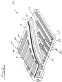
- FIG. 6 Another alternative embodiment 60 of a TFEL display panel having a light absorbing dark layer 62 is illustrated in Fig. 6.
- This embodiment is similar to the embodiment shown in Fig. 2 with the important exception that the light absorbing layer 62 in this embodiment is a graded light absorbing layer and the material is a only a variation of the material used for the second dielectric layer 30 and not a unique material.
- the graded dark layer is a nonstoichoemetric silicon nitride (SiN x ) which provides a high quality light absorbing layer, and can be produced rather easily by controlling the nitrogen/argon gas flow ratio during the standard dielectric deposition process.
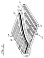
- Fig. 7 shows still another alternative embodiment 70 of the present invention.
- the embodiment 70 of Fig. 7 is similar to the embodiment of Fig. 2; the two embodiments differ primarily in that the position of the dark layer 31 and the second dielectric layer 30 are reversed.
- the remaining layers in the embodiment illustrated in Fig. 7 incorporate the same or substantially the same materials as the embodiment in Fig. 2.
- the multi-color TFEL display of the present invention can have any other configuration that would benefit from the combination of low resistance transparent electrodes, and light absorbing dark material.
- the present invention provides several benefits over the prior art.
- the combination of low resistance electrodes and a layer of light absorbing dark material make multi-color TFEL displays of all sizes brighter.
- a display with low resistance electrodes and a dark layer can be critical in achieving sufficient contrast to provide a directly sunlight viewable multi-color TFEL display.
- the present invention is not limited to multi-color TFEL displays which use ion implantation to implant the activator and co-activators; thermal diffusion or any of the other well known processes may be used.
Landscapes
- Electroluminescent Light Sources (AREA)
Abstract
Claims (10)
- Ecran d'affichage électroluminescent polychrome comprenant:un substrat en verre;une pluralité d'électrodes transparentes parallèles, déposées sur ledit substrat en verre, chacune desdites électrodes transparentes comportant une structure auxiliaire métallique formée sur une partie desdites électrodes et en contact avec cette partie;une première couche diélectrique déposée sur ladite pluralité d'électrodes transparentes;une couche de phosphor déposée sur ladite première couche diélectrique et comportant diverses substances d'activation et de coactivation qui y sont implantées pour constituer une matière luminescente à émission de lumière colorée;une deuxième couche diélectrique déposée sur ladite couche de phosphor;une couche de matière sombre absorbant la lumière, déposée sur ladite deuxième couche diélectrique pour réduire la lumière réfléchie; etune pluralité d'électrodes métalliques déposées chacune en parallèle sur ladite couche de matière sombre absorbant la lumière.
- Ecran d'affichage électroluminescent polychrome pouvant être observé sous la lumière du jour selon la revendication 1, dans lequel chacune desdites structures auxiliaires métalliques comprend une première couche métallique réfractaire, une couche conductrice primaire sur la première couche réfractaire et une deuxième couche métallique réfractaire formée sur la couche conductrice primaire formée de telle sorte que les première et deuxième couches métalliques réfractaires sont capables de protéger la couche conductrice primaire contre l'oxydation quand l'écran d'affichage électroluminescent est soumis à un traitement thermique pour activer ladite couche de phosphor.
- Ecran d'affichage électroluminescent pouvant être observé sous la lumière du jour selon la revendication 2, dans lequel ladite structure métallique auxiliaire recouvre environ 10% ou moins de ladite électrode transparente.
- Ecran d'affichage électroluminescent pouvant être observé sous la lumière du jour selon la revendication 2, dans lequel ladite couche de matière sombre absorbant la lumière est PbMno3.
- Ecran d'affichage électroluminescent pouvant être observé sous la lumière du jour selon la revendication 1, dans lequel ladite couche de matière sombre absorbant la lumière a une résistivité d'au moins 108 ohms/cm.
- Ecran d'affichage électroluminescent pouvant être observé sous la lumière du jour selon la revendication 1, dans lequel ladite couche de matière sombre absorbant la lumière est GeN.
- Ecran d'affichage électroluminescent pouvant être observé sous la lumière du jour selon la revendication 2, dans lequel les bords de ladite structure métallique auxiliaire sont chanfreinés.
- Ecran d'affichage électroluminescent pouvant être observé en présence de la lumière du jour selon la revendication 1, dans lequel ladite couche de matière sombre absorbant la lumière est une couche à gradient de matière sombre absorbant la lumière.
- Ecran d'affichage électroluminescent selon la revendication 1, dans lequel ladite couche à gradient de matière sombre absorbant la lumière comprend un nitrure de silicium non stoechiométrique, SiNx.
- Ecran d'affichage électroluminescent selon la revendication 2, dans lequel ladite structure métallique auxiliaire comprend, en outre une couche d'adhérence formée entre ladite première couche métallique réfractaire et l'électrode transparente, dans lequel ladite couche d'adhérence est capable d'adhérer à l'électrode transparente et à ladite première couche métallique réfractaire.
Applications Claiming Priority (3)
| Application Number | Priority Date | Filing Date | Title |
|---|---|---|---|
| US62869 | 1993-05-17 | ||
| US08/062,869 US5445899A (en) | 1992-12-16 | 1993-05-17 | Color thin film electroluminescent display |
| PCT/US1994/005543 WO1994027418A1 (fr) | 1993-05-17 | 1994-05-17 | Dispositif d'affichage couleur electroluminescent a couches minces |
Publications (2)
| Publication Number | Publication Date |
|---|---|
| EP0706748A1 EP0706748A1 (fr) | 1996-04-17 |
| EP0706748B1 true EP0706748B1 (fr) | 1997-09-03 |
Family
ID=22045385
Family Applications (1)
| Application Number | Title | Priority Date | Filing Date |
|---|---|---|---|
| EP94917429A Expired - Lifetime EP0706748B1 (fr) | 1993-05-17 | 1994-05-17 | Dispositif d'affichage couleur electroluminescent a couches minces |
Country Status (8)
| Country | Link |
|---|---|
| US (1) | US5445899A (fr) |
| EP (1) | EP0706748B1 (fr) |
| JP (1) | JPH08510589A (fr) |
| KR (1) | KR960702727A (fr) |
| CA (1) | CA2163102A1 (fr) |
| RU (1) | RU2131174C1 (fr) |
| TW (1) | TW273066B (fr) |
| WO (1) | WO1994027418A1 (fr) |
Families Citing this family (22)
| Publication number | Priority date | Publication date | Assignee | Title |
|---|---|---|---|---|
| US5578225A (en) * | 1995-01-19 | 1996-11-26 | Industrial Technology Research Institute | Inversion-type FED method |
| GB2312326B (en) * | 1995-04-18 | 1999-07-28 | Cambridge Display Tech Ltd | Electroluminescent device |
| US5773130A (en) * | 1996-06-06 | 1998-06-30 | Motorola, Inc. | Multi-color organic electroluminescent device |
| US5986401A (en) * | 1997-03-20 | 1999-11-16 | The Trustee Of Princeton University | High contrast transparent organic light emitting device display |
| US6121727A (en) * | 1997-04-04 | 2000-09-19 | Mitsubishi Chemical Corporation | Organic electroluminescent device |
| KR100209657B1 (ko) * | 1997-04-24 | 1999-07-15 | 구자홍 | 다색 전계 발광 디스플레이 어레이 패널 및 그 제조방법 |
| US6107736A (en) * | 1997-06-02 | 2000-08-22 | Motorola, Inc. | Organic electroluminescent display device and method of fabrication |
| US6069443A (en) * | 1997-06-23 | 2000-05-30 | Fed Corporation | Passive matrix OLED display |
| JPH11144877A (ja) * | 1997-11-10 | 1999-05-28 | Fuji Electric Co Ltd | 有機発光素子 |
| US5986391A (en) * | 1998-03-09 | 1999-11-16 | Feldman Technology Corporation | Transparent electrodes |
| US6106352A (en) * | 1998-03-18 | 2000-08-22 | Sanyo Electric Co., Ltd. | Method for fabrication of organic electroluminescent device |
| EP0969517B1 (fr) | 1998-07-04 | 2005-10-12 | International Business Machines Corporation | Electrode pour dispositifs électro-optiques |
| JP3887984B2 (ja) | 1999-02-05 | 2007-02-28 | 松下電器産業株式会社 | 多色発光分散型elランプ |
| US6843697B2 (en) * | 1999-06-25 | 2005-01-18 | Micron Display Technology, Inc. | Black matrix for flat panel field emission displays |
| JP2002025781A (ja) * | 2000-07-07 | 2002-01-25 | Nec Corp | 有機el素子およびその製造方法 |
| JP5243675B2 (ja) * | 2000-08-14 | 2013-07-24 | レノボ シンガポール プライヴェート リミテッド | コンピュータ装置および記憶媒体 |
| KR100424204B1 (ko) * | 2001-08-10 | 2004-03-24 | 네오뷰코오롱 주식회사 | 무반사 유기 전계발광소자 |
| KR100404203B1 (ko) * | 2001-08-21 | 2003-11-03 | 엘지전자 주식회사 | 트리플 스캔 구조의 유기 el 소자 |
| KR100624307B1 (ko) * | 2005-02-23 | 2006-09-19 | 제일모직주식회사 | 표시장치용 저반사율의 휘도 향상 다층 광학필름 및 이를이용한 유기발광다이오드 표시장치 |
| US20080218073A1 (en) * | 2007-03-08 | 2008-09-11 | Adrian Kitai | Electroluminescent Nixels and Elements with Single-Sided Electrical Contacts |
| US7567370B2 (en) * | 2007-07-26 | 2009-07-28 | Hewlett-Packard Development Company, L.P. | Color display having layer dependent spatial resolution and related method |
| JP5323841B2 (ja) * | 2008-09-01 | 2013-10-23 | シャープ株式会社 | 有機エレクトロルミネセンスパネル、有機エレクトロルミネセンスディスプレイ、有機エレクトロルミネセンス照明、及び、それらの製造方法 |
Family Cites Families (10)
| Publication number | Priority date | Publication date | Assignee | Title |
|---|---|---|---|---|
| US4287449A (en) * | 1978-02-03 | 1981-09-01 | Sharp Kabushiki Kaisha | Light-absorption film for rear electrodes of electroluminescent display panel |
| US4602189A (en) * | 1983-10-13 | 1986-07-22 | Sigmatron Nova, Inc. | Light sink layer for a thin-film EL display panel |
| DE3561435D1 (en) * | 1984-03-23 | 1988-02-18 | Matsushita Electric Ind Co Ltd | Thin film el panel |
| US4613793A (en) * | 1984-08-06 | 1986-09-23 | Sigmatron Nova, Inc. | Light emission enhancing dielectric layer for EL panel |
| JPS61284092A (ja) * | 1985-06-07 | 1986-12-15 | アルプス電気株式会社 | 薄膜el表示素子 |
| US4963788A (en) * | 1988-07-14 | 1990-10-16 | Planar Systems, Inc. | Thin film electroluminescent display with improved contrast |
| US5559399A (en) * | 1992-06-11 | 1996-09-24 | Norden Systems, Inc. | Low resistance, thermally stable electrode structure for electroluminescent displays |
| US5517080A (en) * | 1992-12-14 | 1996-05-14 | Westinghouse Norden Systems Inc. | Sunlight viewable thin film electroluminescent display having a graded layer of light absorbing dark material |
| DE69326162T2 (de) * | 1992-12-14 | 2000-04-27 | United Technologies Corp | Im sonnenlicht sichtbare elektrolumineszente dünn-schicht-vorrichtung mit geschwärzter metallelektrode |
| US5445898A (en) * | 1992-12-16 | 1995-08-29 | Westinghouse Norden Systems | Sunlight viewable thin film electroluminescent display |
-
1993
- 1993-05-17 US US08/062,869 patent/US5445899A/en not_active Expired - Fee Related
-
1994
- 1994-05-17 CA CA002163102A patent/CA2163102A1/fr not_active Abandoned
- 1994-05-17 WO PCT/US1994/005543 patent/WO1994027418A1/fr active IP Right Grant
- 1994-05-17 JP JP6525801A patent/JPH08510589A/ja active Pending
- 1994-05-17 RU RU95122469A patent/RU2131174C1/ru active
- 1994-05-17 KR KR1019950705117A patent/KR960702727A/ko active IP Right Grant
- 1994-05-17 EP EP94917429A patent/EP0706748B1/fr not_active Expired - Lifetime
- 1994-06-03 TW TW083105078A patent/TW273066B/zh active
Also Published As
| Publication number | Publication date |
|---|---|
| CA2163102A1 (fr) | 1994-11-24 |
| JPH08510589A (ja) | 1996-11-05 |
| TW273066B (fr) | 1996-03-21 |
| RU2131174C1 (ru) | 1999-05-27 |
| EP0706748A1 (fr) | 1996-04-17 |
| WO1994027418A1 (fr) | 1994-11-24 |
| US5445899A (en) | 1995-08-29 |
| KR960702727A (ko) | 1996-04-27 |
Similar Documents
| Publication | Publication Date | Title |
|---|---|---|
| EP0706748B1 (fr) | Dispositif d'affichage couleur electroluminescent a couches minces | |
| US5400047A (en) | High brightness thin film electroluminescent display with low OHM electrodes | |
| EP0645073B1 (fr) | Structure d'electrodes thermiquement stable a faible resistance pour des affichages electroluminescents | |
| US5517080A (en) | Sunlight viewable thin film electroluminescent display having a graded layer of light absorbing dark material | |
| US5445898A (en) | Sunlight viewable thin film electroluminescent display | |
| US5521465A (en) | Sunlight viewable thin film electroluminscent display having darkened metal electrodes | |
| KR20040080531A (ko) | 박막트랜지스터 및 이를 구비한 평판표시소자 | |
| EP0298745B1 (fr) | Dispositif électroluminescent à film mince | |
| JP2000173768A (ja) | 薄膜電界発光装置及びその製造方法 | |
| US20020125495A1 (en) | Thin film alternating current electroluminescent displays | |
| US4947081A (en) | Dual insulation oxynitride blocking thin film electroluminescence display device | |
| US4683044A (en) | Method of manufacturing an electroluminescent panel without any adverse influence on an underlying layer | |
| JP2848277B2 (ja) | El素子の製造方法 | |
| JP3258780B2 (ja) | エレクトロルミネッセンス素子とその製造方法 | |
| EP0450077A1 (fr) | Element electroluminescent a film mince et procede de fabrication de cet element | |
| JP3308308B2 (ja) | 薄膜elディスプレイ素子及びその製造方法 | |
| JP2679322B2 (ja) | 2重絶縁薄膜エレクトロルミネセンス装置の製造方法 | |
| JPH05226075A (ja) | 酸化物透明導電膜を有する電子素子 | |
| JP3487618B2 (ja) | エレクトロルミネッセンス素子 | |
| JPS6141111B2 (fr) | ||
| JPH01304694A (ja) | 薄膜el素子 | |
| JPH11102785A (ja) | El素子 | |
| JPS6180793A (ja) | 薄膜el素子 | |
| JPS63181296A (ja) | 誘電体膜の形成方法 | |
| JPS6210435B2 (fr) |
Legal Events
| Date | Code | Title | Description |
|---|---|---|---|
| PUAI | Public reference made under article 153(3) epc to a published international application that has entered the european phase |
Free format text: ORIGINAL CODE: 0009012 |
|
| 17P | Request for examination filed |
Effective date: 19951120 |
|
| AK | Designated contracting states |
Kind code of ref document: A1 Designated state(s): FR GB |
|
| GRAG | Despatch of communication of intention to grant |
Free format text: ORIGINAL CODE: EPIDOS AGRA |
|
| 17Q | First examination report despatched |
Effective date: 19960822 |
|
| GRAH | Despatch of communication of intention to grant a patent |
Free format text: ORIGINAL CODE: EPIDOS IGRA |
|
| GRAH | Despatch of communication of intention to grant a patent |
Free format text: ORIGINAL CODE: EPIDOS IGRA |
|
| GRAA | (expected) grant |
Free format text: ORIGINAL CODE: 0009210 |
|
| AK | Designated contracting states |
Kind code of ref document: B1 Designated state(s): FR GB |
|
| ET | Fr: translation filed | ||
| PLBE | No opposition filed within time limit |
Free format text: ORIGINAL CODE: 0009261 |
|
| STAA | Information on the status of an ep patent application or granted ep patent |
Free format text: STATUS: NO OPPOSITION FILED WITHIN TIME LIMIT |
|
| 26N | No opposition filed | ||
| PGFP | Annual fee paid to national office [announced via postgrant information from national office to epo] |
Ref country code: FR Payment date: 20000502 Year of fee payment: 7 |
|
| PGFP | Annual fee paid to national office [announced via postgrant information from national office to epo] |
Ref country code: GB Payment date: 20000504 Year of fee payment: 7 |
|
| PG25 | Lapsed in a contracting state [announced via postgrant information from national office to epo] |
Ref country code: GB Free format text: LAPSE BECAUSE OF NON-PAYMENT OF DUE FEES Effective date: 20010517 |
|
| GBPC | Gb: european patent ceased through non-payment of renewal fee |
Effective date: 20010517 |
|
| PG25 | Lapsed in a contracting state [announced via postgrant information from national office to epo] |
Ref country code: FR Free format text: LAPSE BECAUSE OF NON-PAYMENT OF DUE FEES Effective date: 20020131 |