EP0705783B1 - Verfahren und Vorrichtung zum Stoppen eines Satzes von Rollen - Google Patents
Verfahren und Vorrichtung zum Stoppen eines Satzes von Rollen Download PDFInfo
- Publication number
- EP0705783B1 EP0705783B1 EP95114462A EP95114462A EP0705783B1 EP 0705783 B1 EP0705783 B1 EP 0705783B1 EP 95114462 A EP95114462 A EP 95114462A EP 95114462 A EP95114462 A EP 95114462A EP 0705783 B1 EP0705783 B1 EP 0705783B1
- Authority
- EP
- European Patent Office
- Prior art keywords
- roll
- stop
- rolls
- gages
- slitter
- Prior art date
- Legal status (The legal status is an assumption and is not a legal conclusion. Google has not performed a legal analysis and makes no representation as to the accuracy of the status listed.)
- Expired - Lifetime
Links
- 238000000034 method Methods 0.000 title claims abstract description 17
- 238000005096 rolling process Methods 0.000 abstract description 9
- 230000006378 damage Effects 0.000 description 9
- 230000003534 oscillatory effect Effects 0.000 description 4
- 208000027418 Wounds and injury Diseases 0.000 description 3
- 230000002950 deficient Effects 0.000 description 2
- 230000007257 malfunction Effects 0.000 description 2
- 238000012544 monitoring process Methods 0.000 description 2
- 239000002390 adhesive tape Substances 0.000 description 1
- 238000010276 construction Methods 0.000 description 1
- 230000007547 defect Effects 0.000 description 1
- 238000010586 diagram Methods 0.000 description 1
- 230000000694 effects Effects 0.000 description 1
- 230000003028 elevating effect Effects 0.000 description 1
- 239000003292 glue Substances 0.000 description 1
- 208000014674 injury Diseases 0.000 description 1
- 238000009434 installation Methods 0.000 description 1
- 230000000717 retained effect Effects 0.000 description 1
- 238000005303 weighing Methods 0.000 description 1
Images
Classifications
-
- B—PERFORMING OPERATIONS; TRANSPORTING
- B65—CONVEYING; PACKING; STORING; HANDLING THIN OR FILAMENTARY MATERIAL
- B65G—TRANSPORT OR STORAGE DEVICES, e.g. CONVEYORS FOR LOADING OR TIPPING, SHOP CONVEYOR SYSTEMS OR PNEUMATIC TUBE CONVEYORS
- B65G47/00—Article or material-handling devices associated with conveyors; Methods employing such devices
- B65G47/74—Feeding, transfer, or discharging devices of particular kinds or types
- B65G47/88—Separating or stopping elements, e.g. fingers
- B65G47/8807—Separating or stopping elements, e.g. fingers with one stop
- B65G47/8823—Pivoting stop, swinging in or out of the path of the article
-
- B—PERFORMING OPERATIONS; TRANSPORTING
- B65—CONVEYING; PACKING; STORING; HANDLING THIN OR FILAMENTARY MATERIAL
- B65H—HANDLING THIN OR FILAMENTARY MATERIAL, e.g. SHEETS, WEBS, CABLES
- B65H19/00—Changing the web roll
- B65H19/22—Changing the web roll in winding mechanisms or in connection with winding operations
- B65H19/30—Lifting, transporting, or removing the web roll; Inserting core
-
- B—PERFORMING OPERATIONS; TRANSPORTING
- B65—CONVEYING; PACKING; STORING; HANDLING THIN OR FILAMENTARY MATERIAL
- B65G—TRANSPORT OR STORAGE DEVICES, e.g. CONVEYORS FOR LOADING OR TIPPING, SHOP CONVEYOR SYSTEMS OR PNEUMATIC TUBE CONVEYORS
- B65G2205/00—Stopping elements used in conveyors to stop articles or arrays of articles
- B65G2205/02—Stopping elements used in conveyors to stop articles or arrays of articles where the stop device is adaptable to the size of the article or array
-
- B—PERFORMING OPERATIONS; TRANSPORTING
- B65—CONVEYING; PACKING; STORING; HANDLING THIN OR FILAMENTARY MATERIAL
- B65G—TRANSPORT OR STORAGE DEVICES, e.g. CONVEYORS FOR LOADING OR TIPPING, SHOP CONVEYOR SYSTEMS OR PNEUMATIC TUBE CONVEYORS
- B65G2205/00—Stopping elements used in conveyors to stop articles or arrays of articles
- B65G2205/06—Cushioned or damping stop devices, e.g. using springs or other mechanical actions
-
- B—PERFORMING OPERATIONS; TRANSPORTING
- B65—CONVEYING; PACKING; STORING; HANDLING THIN OR FILAMENTARY MATERIAL
- B65H—HANDLING THIN OR FILAMENTARY MATERIAL, e.g. SHEETS, WEBS, CABLES
- B65H2301/00—Handling processes for sheets or webs
- B65H2301/40—Type of handling process
- B65H2301/41—Winding, unwinding
- B65H2301/414—Winding
- B65H2301/4148—Winding slitting
-
- B—PERFORMING OPERATIONS; TRANSPORTING
- B65—CONVEYING; PACKING; STORING; HANDLING THIN OR FILAMENTARY MATERIAL
- B65H—HANDLING THIN OR FILAMENTARY MATERIAL, e.g. SHEETS, WEBS, CABLES
- B65H2301/00—Handling processes for sheets or webs
- B65H2301/40—Type of handling process
- B65H2301/41—Winding, unwinding
- B65H2301/417—Handling or changing web rolls
- B65H2301/4171—Handling web roll
- B65H2301/4172—Handling web roll by circumferential portion, e.g. rolling on circumference
-
- Y—GENERAL TAGGING OF NEW TECHNOLOGICAL DEVELOPMENTS; GENERAL TAGGING OF CROSS-SECTIONAL TECHNOLOGIES SPANNING OVER SEVERAL SECTIONS OF THE IPC; TECHNICAL SUBJECTS COVERED BY FORMER USPC CROSS-REFERENCE ART COLLECTIONS [XRACs] AND DIGESTS
- Y10—TECHNICAL SUBJECTS COVERED BY FORMER USPC
- Y10S—TECHNICAL SUBJECTS COVERED BY FORMER USPC CROSS-REFERENCE ART COLLECTIONS [XRACs] AND DIGESTS
- Y10S414/00—Material or article handling
- Y10S414/124—Roll handlers
-
- Y—GENERAL TAGGING OF NEW TECHNOLOGICAL DEVELOPMENTS; GENERAL TAGGING OF CROSS-SECTIONAL TECHNOLOGIES SPANNING OVER SEVERAL SECTIONS OF THE IPC; TECHNICAL SUBJECTS COVERED BY FORMER USPC CROSS-REFERENCE ART COLLECTIONS [XRACs] AND DIGESTS
- Y10—TECHNICAL SUBJECTS COVERED BY FORMER USPC
- Y10S—TECHNICAL SUBJECTS COVERED BY FORMER USPC CROSS-REFERENCE ART COLLECTIONS [XRACs] AND DIGESTS
- Y10S83/00—Cutting
- Y10S83/929—Particular nature of work or product
- Y10S83/949—Continuous or wound supply
-
- Y—GENERAL TAGGING OF NEW TECHNOLOGICAL DEVELOPMENTS; GENERAL TAGGING OF CROSS-SECTIONAL TECHNOLOGIES SPANNING OVER SEVERAL SECTIONS OF THE IPC; TECHNICAL SUBJECTS COVERED BY FORMER USPC CROSS-REFERENCE ART COLLECTIONS [XRACs] AND DIGESTS
- Y10—TECHNICAL SUBJECTS COVERED BY FORMER USPC
- Y10T—TECHNICAL SUBJECTS COVERED BY FORMER US CLASSIFICATION
- Y10T83/00—Cutting
- Y10T83/04—Processes
- Y10T83/0448—With subsequent handling [i.e., of product]
- Y10T83/0467—By separating products from each other
-
- Y—GENERAL TAGGING OF NEW TECHNOLOGICAL DEVELOPMENTS; GENERAL TAGGING OF CROSS-SECTIONAL TECHNOLOGIES SPANNING OVER SEVERAL SECTIONS OF THE IPC; TECHNICAL SUBJECTS COVERED BY FORMER USPC CROSS-REFERENCE ART COLLECTIONS [XRACs] AND DIGESTS
- Y10—TECHNICAL SUBJECTS COVERED BY FORMER USPC
- Y10T—TECHNICAL SUBJECTS COVERED BY FORMER US CLASSIFICATION
- Y10T83/00—Cutting
- Y10T83/202—With product handling means
- Y10T83/2074—Including means to divert one portion of product from another
-
- Y—GENERAL TAGGING OF NEW TECHNOLOGICAL DEVELOPMENTS; GENERAL TAGGING OF CROSS-SECTIONAL TECHNOLOGIES SPANNING OVER SEVERAL SECTIONS OF THE IPC; TECHNICAL SUBJECTS COVERED BY FORMER USPC CROSS-REFERENCE ART COLLECTIONS [XRACs] AND DIGESTS
- Y10—TECHNICAL SUBJECTS COVERED BY FORMER USPC
- Y10T—TECHNICAL SUBJECTS COVERED BY FORMER US CLASSIFICATION
- Y10T83/00—Cutting
- Y10T83/647—With means to convey work relative to tool station
- Y10T83/6476—Including means to move work from one tool station to another
- Y10T83/6489—Slitter station
Definitions
- the present invention relates to a method according to the preamble of claim 1 for stopping a set of multiple rolls, often referred to in short as a set, in a controlled fashion.
- the invention also concerns an apparatus according to the preamble of claim 8 suited for implementing the method.
- the web is manufactured in machine rolls having a width equal to the full web width, whereby the machine rolls must be slit into rolls of narrower width according to order prior to their delivery to the customer. Slitting is performed on a slitter in which the wider machine roll is unwound and the web is slit into narrower trimmed webs which are rewound again into rolls.
- the width of the rolls to be produced on the slitter is adjusted according to orders received from customers, and a single machine roll may conventionally be slit into rolls of different widths.
- the ready-wound rolls are ejected from the slitter onto a downward ramp, on which they roll down to a conveyor that takes the rolls to the wrapping area.
- the rolls leave the slitter at very close proximity, with the rolls ends almost abutting. However, the rolls must be somewhat outdistanced on the conveyor and at the wrapping stations.
- the rolls are arranged in a proper order and at proper mutual distances on the conveyor by separating the ready-slit rolls into sets. Each set comprises those rolls that are desired to be loaded sequentially onto the conveyor.
- the rolls slit from the machine roll are separated into sets either on the slitter, whereby the slitter separates the sets to both sides of the slitter, or alternatively, all rolls are ejected away from the slitter along a single downward ramp and then stopped by means of stop flaps placed on the downward ramp, whereby the flaps release the rolls to roll to the conveyor in a determined order.
- a set can be defined as such a set of rolls which is received from a slitter or other station already separated from each other but still requiring simultaneous stopping.
- the transfer of such a roll set may involve the use of car conveyors lifts or ramp systems.
- the oscillatory rolling motion causes damage to the roll and the web wound on the roll may break invisibly under the roll surface and cause unwinding of the roll if the glue bond of the roll tail fails.
- a slitter may not necessarily involve continuous monitoring by the shift personnel, the defective rolls can easily reach the shipping system causing defect reports from that section of the line.
- the damage on the roll is found, the damaged layers are removed and the tail of the web is reattached to the roll using self-adhesive tape.
- the stopping situations of a set often involve a risk of injury particularly when manual stopping of a roll is attempted prior to the natural stopping of its oscillatory motion.
- the kinetic energy of a roll weighing several tons is extremely high even at slow speeds, and as a plurality of rolls exist on the ramp during the transfer phase, the risk of becoming knocked by the rolls is high. Manual stopping of the rolls may also be attempted to speed the operation of the line as the oscillatory motion of the rolls slows down the operating speed of the line.
- a downward retractable, full-width stop gage is less frequently employed than a slanted stop gage.
- This type of stop gage is operated in the same fashion as the stop gages of the conveyor system. As the roll hits the stop gage, the gage retracts and simultaneously slows down the roll motion and finally stops the roll in a controlled fashion on the conveyor. However, these stops operate reliably with such roll weights for which they have been adjusted. Because the roll sizes incoming from the slitter vary widely, the function of the stop gage cannot be adjusted optimally. Yet, a more serious problem surpassing that involving the stop gage control arises from the nonsimultaneous arrival of the rolls on the stop gage.
- the stop gage commences its retraction movement already at the hitting of the first roll on the gage, whereby the subsequent rolls hit a retracting or even stationary stop gage. If the end position of the roll braking motion of the stop gage is flush with the floor level, the rolls may continue rolling over and past the stop gage further along the floor of the mill. Hitting a stationary stop gage will readily damage the roll, whereby the web layers must be removed from the roll which results in a disturbance in the operation of the line. In the opposite case of insufficient line monitoring, defective rolls may be shipped to the customer. The differences in the rolling speed of the rolls on the ramp are caused by, i.a, the surface hardness differences between the individual rolls causing appreciable variation in the rolling speed of the rolls.
- a roll stop gage is an arm pivotally mounted at its one end and adapted for motion control by means of a pneumatic cylinder.
- a roll stop operates so that along with its rolling motion, the roll hits a contact roll mounted to the distal end of the stop arm and begins to swing the arm toward the direction of the roll motion.
- the arm actuates a pneumatic cylinder equipped with an outlet throttle valve at that side of the cylinder actuated during the braking of the roll motion.
- the throttling action slows down the cylinder stroke rate, as well as thereby also the roll motion, whereby the roll motion is brought to a halt.
- FR-A-26 82 053 discloses a roll stop gage with an air-cushion bellow as the braking element but in connection with metallurgical installations.
- the goal of the invention is accomplished by providing the downward ramp with a plurality of adjacent stop gages which can be controlled to their operating and home positions, respectively.
- a required number of the stop gages disposed along the rotating path of the roll is controlled to operate separately for each roll, while the rest of the stop gages are left in their home positions.
- the principle of the invention is implemented in conjunction with a slitter so that the downward ramp in front of the conveyor is provided with a number of adjacent stop gages, which can be controlled to either their operating or home positions. For each roll, a required number of the stop gages is selected to operate, while the rest of the stop gages are left in their home positions.
- the invention offers significant benefits.
- the transfer of rolls by means of a downward ramp from a slitter or other station can be implemented in a controlled fashion irrespective of a wide size distribution of the rolls.
- the stopping force may be controlled in a variety of fashions by controlling the stop gages individually and varying the number of stop gages used for stopping a specific roll.
- the roll diameter may vary, it is additionally necessary to control the stopping power of the stop gages so that rolls of different weight but of equal width can be stopped without causing damage to the rolls. Surface damage to the rolls is reduced, because the rolls are prevented from hitting fixed or stationary stop gages at a high speed.
- the function of stop gages performing the stopping of a specific roll is entirely independent from the function of the other stop gages.
- Selected stop gages can be lowered in their home positions flush with the floor level, whereby desired rolls may be allowed to pass over the conveyor, while the rest of the rolls can be stopped onto the conveyor.
- the individual stop gages have a design that provides satisfactory function even if the stopping force is incorrectly set for the roll size to be handled. Consequently, the risk of damage in conjunction with malfunction situations is reduced.
- the function of the stop gages can be readily controlled also manually, while the optimum controllability and most flexible function are achieved by connecting the stop gage system to the control computer of the slitter and the conveyor system. Then, the stopping effect and number of the stop gages can be set separately for each roll on the basis of roll information stored in the control system.
- the separating flaps presently in use can be replaced by the stop gage system according to the invention, whereby the rolls can be stopped smoothly also on the separating flaps.
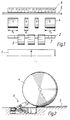
- the system according to the invention is illustrated adapted to a slitter 1 which is shown ejecting slit rolls 3, 4 to the same side of the slitter, while the invention can as well be adapted to such slitters that separate the rolls to the opposite sides of the station, and further, in conjunction with other such equipment in which the rolls are transferred along a downward ramp.
- the rolls 3, 4 rotate along a ramp 7 to separating flaps 2.
- the separating flaps 2 first stop the rolls 3, 4 onto the ramp 7 and then release a portion of the rolls to rotate further along the ramp to a conveyor 5.
- Half of the rolls are retained behind the separating flaps, while the other half is allowed to rotate further to the conveyor 5 behind which are located the set stop gages 6.
- the number of the stop gages 6 is fourteen and they are numbered sequentially in Fig. 1 by consecutive numbers from 1 to 14.
- the first set comprising rolls 4 has wide rolls at the sides and two narrow rolls at the center.
- the width of the individual stop gages 6 is selected so that the width of the stop gage 6 is equal to the width B 1 of the narrowest roll to be received from the slitter.
- the total width of the stop gage system is determined by the width of the rolls to be received from the slitter and by using a large number of narrow-width stop gages, the system may be made extremely flexible, while obviously the system price becomes higher when the number of stop gages is increased.
- the width of the stop gages 6 is advantageous to adapt the width of the stop gages 6 according to the width distribution of the rolls to be manufactured so that the roll widths will be an integral multiple of the width of the stop gages; however, this requirement is not by any means compelling, since the stop gages need not necessarily extend over the entire width of a roll.
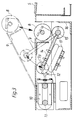
- the roll 4 is shown hitting the stop gage 6.
- the roll 4 first hits the stop gage at a roller 8 which is mounted on bearings on a moving lever 9.
- the opposite end of the lever 9 is adapted to slide supported by a pin 11 along a slot 10, and by means of a pivotal joint 13 to the center point of the lever 9 is attached a guide lever 14 whose other end is attached by means of a pivotal joint 15 to the stop gage body 16.
- Under the guide lever 14 is arranged an air-cushion bellows 17.
- the stop gage 6 is placed aside the conveyor 5 So that in its operating position the roll 8 is approximately aligned to the edge of the conveyor.
- the number of individual stop gages and their location are selected in set cushion stop system so as to cope with the location and width of the rolls 4 in the set.
- the unselected stop gages are controlled into their home positions, whereby they remain flush with the floor level.
- Each stop gage may be adjusted pneumatically according to the minimum-size roll, whereby the stopping power for larger rolls is selected by controlling a greater number of stop gages to operate simultaneously in the stopping of the roll.
- the stop gages 1, 2, 3, 6, 9, 12, 13 and 14 are controlled to operate for stopping the rolls 4.
- the stop gages 4, 5, 7, 8, 10 and 11 are controlled to operate.
- the selection of the stop gages may be done manually from a control panel, or alternatively, the selection may be linked to the control of the slitter 1 or the separating flaps 2.
- the position signal of the separating flaps 2 is readily available, because the selection of the separating flaps 2 can be directly connected to the selection of the stop gages 6.
- the position of the stop gages is sensed by means of sensor 12 mounted on the slot 10.
- the lever 9 of the stop gage begins yielding backward along by the slot 10.
- the movement of the lever 9 and the roller 8 is controlled by the guide lever 14 so that the movement of the roller 8 is principally guided downward.
- the translational speed of the stop gage is controlled by means of the inflating pressure of the air-cushion bellows 17 located below the guide lever 14.
- the basic adjustment of bellows pressure may be, e.g., such that it provides suitable stopping power by the stop gage for the lightest rolls to be handled, and for rolls of larger width, a greater number of stop gages is activated to provide more stopping power.
- the stopping power may be increased by elevating the inflation pressure of the air-cushion bellows.
- an air-cushion bellows is a particularly advantageouS device for generating the stopping power.
- the area of the bellows is large, whereby a high stopping power is achieved at a low pressure.
- a bellows is not sensitive to changes in roll size, because the stopping power generated by the bellows increases when the bellows volume is compressed, whereby the bellows automatically compensates for the impacts caused by oversize rolls, and even during a malfunction situation, the stop gage can receive the roll with a relatively gentle stopping action.
- stop gages can be employed different from that described above.
- all conventional stop gage constructions are suited for the implementation of the method according to the invention, while such stop gages that can be controlled entirely flush with the floor level facilitate the transfer of rolls over the conveyor to the mill floor.
- the home and operating positions of the gage need not necessarily be different positions in the physical sense, but rather the stop gage may be controlled to its "home" position by adjusting the stopping power of the gage sufficiently low, whereby the gage will not brake down the movement of the roll.
- the stopping power may also be generated by electromechanical or hydraulic means, while the pneumatic means are preferred for their soft function. Further, the stopping power generated by pneumatic devices is easy to control.
- the most typical application of the invention is in the stopping of a roll set incoming from a slitter to a conveyor.
- the invention may be employed in other similar points of application. Equivalent stopping needs occur always when rolls are transferred along a ramp.
- the rolls to be transferred may be received from, e.g., another conveyor or a roll store.
- the linear row of stop gages according to the invention is capable of replacing stop flaps in a fashion that can stop the rolls on the downward ramp, whereby the braking-type stop gages provide a smoother and more controlled stopping than conventional separating flaps.
- improved operational safety is achieved as the oscillatory motion of the rolls is eliminated, and simultaneously, higher rolling speeds can be used; that is, longer and steeper graded downward ramps can be used.
Landscapes
- Engineering & Computer Science (AREA)
- Mechanical Engineering (AREA)
- Rollers For Roller Conveyors For Transfer (AREA)
- Spinning Or Twisting Of Yarns (AREA)
- Diaphragms For Electromechanical Transducers (AREA)
- Accessories And Tools For Shearing Machines (AREA)
- Container Filling Or Packaging Operations (AREA)
- Lubricants (AREA)
- Bending Of Plates, Rods, And Pipes (AREA)
- Control Of Conveyors (AREA)
Claims (12)
- Verfahren zum Stoppen eines von einem Rollenschneider (1) oder einer ähnlichen Station aufgenommenen Rollensatzes, der einen Teil (4) von Rollen (3, 4) umfaßt, die durch den Rollenschneider (1) von einer Maschinenrolle aufgeteilt wurden, oder eines ähnlichen Rollensatz, der entlang einer abschüssigen Rampe (7) gerollt wird, mit einem Stop-Justierer (6), der die Rollen durch Verlangsamung ihrer Bewegung stoppt,
gekennzeichnet durch folgende Verfahrensschritte:für jede Rolle (4) des zu stoppenden Rollensatzes wird für eine Betriebsstellung aus einer Reihe mehrerer Stop-Justierer (6), die in Verbindung mit der abwärts geneigten Rampe (7) angeordnet sind, mindestens ein Stop-Justierer (6) ausgewählt, der im Weg der Rolle (4) angeordnet ist,die anderen Stop-Justierer (6) werden in ihre Ruhestellung gesetzt, unddie sich der Reihe der Stop-Justierer (6) annähernden Rollen (4) werden auf einem Fördergerät (5) durch Verlangsamung ihrer Bewegung durch die ausgewählten Stop-Justierer (6) gestoppt. - Verfahren nach Anspruch 1, gekennzeichnet durch das Stoppen der Rollen (4) auf dem Fördergerät (5) mit Hilfe der Reihe von Stop-Justierern (6), die auf der gegenüberliegenden Seite des Fördergerätes (5) bezüglich der abschüssigen, in Verbindung mit dem Rollenschneider (1) vorgesehenen Rampe (7) angeordnet ist, deren unteres Ende an dem Fördergerät endet.
- Verfahren nach Anspruch 1 oder 2, gekennzeichnet durch die separate Steuerung der Stopkraft für jede Rolle durch Änderung der Anzahl der betätigten Stop-Justierer (6).
- Verfahren nach Anspruch 1 oder 2, gekennzeichnet durch die separate Steuerung der Stopkraft für jede Rolle durch separate Änderung der Bremskraft jedes Stop-Justierers (6).
- Verfahren nach Anspruch 1 oder 2, gekennzeichnet durch die Steuerung der Stopkraft für jede Rolle durch Änderung sowohl der Anzahl der betätigten Stop-Justierer (6) als auch der Bremskraft separat für jeden Stop-Justierer.
- Verfahren nach einem der vorhergehenden Ansprüchen, bei dem die von dem Rollenschneider (1) ankommenden Rollen (3, 4) durch auf der abschüssigen Rampe (7) angeordnete Trennklappen (2) in Rollensätze aufgeteilt werden, gekennzeichnet durch die Auswahl der betätigten Stop-Justierer (6) aufgrund der Position der Trennklappen (2).
- Verfahren nach einem der vorhergehenden Ansprüche 14, bei dem die von dem Rollenschneider (1) ankommenden Rollen (3, 4) auf dem Rollenschneider (1) durch Führung der Rollen zu beiden Seiten des Rollenschneiders (1) in Rollensätze aufgeteilt werden, gekennzeichnet durch die Auswahl der betätigten Stop-Justierer (6) aufgrund der von dem Rollenschneider (1) erhaltenen Steuerinformationen.
- Anlage zum Stoppen eines von einem Rollenschneider (1) oder einer ähnlichen Station erhaltenen Rollensatzes in einem System, das mindestens eine abschüssige Rampe (7) mit einem die Rollen durch Verlangsamung ihrer Bewegung stoppenden Stop-Justierer (6) und ein Betätigungsglied zur Zuführung der Rollen auf die abschüssige Rampe (7) aufweist, gekennzeichnet durch eine Reihe von mehreren, in Verbindung mit der abschüssigen Rampe (7) angeordneten Stop-Justierern (6), die in eine Ruhestellung und eine Betriebsstellung steuerbar sind, so daß entlang des Wegs der zu stoppenden Rolle (4) mindestens ein Stop-Justierer (6) zum gesteuerten Betrieb angeordnet ist.
- Anlage nach Anspruch 8 in einem System umfassend den Rollenschneider (1), mindestens die neben dem Rollenschneider angeordnete abschüssige Rampe (7) und ein an dem unteren Ende der abschüssigen Rampe (7) angeordnetes Fördergerät (5) (5), gekennzeichnet durch die Reihe von mehreren Stop-Justierern (6), die an der bezüglich der abschüssigen Rampe (7) gegenüberliegenden Seite des Fördergeräts (5) angeordnet ist, wobei die Stop-Justierer in die Ruhestellung beziehungsweise in die Betriebsstellung steuerbar sind, so daß entlang des Rollwegs der zu stoppenden Rolle (4) mindestens ein Stop-Justierer (6) für einen gesteuerten Betrieb angeordnet ist.
- Anlage nach Anspruch 8 oder 9, dadurch gekennzeichnet, daß die Breite der einzelnen Stop-Justierer (6) entsprechend der Breite der schmalsten Rolle ausgewählt ist.
- Anlage nach Anspruch 8-10, umfassend einen Körper (16) und einen Stop-Hebel (9) , an dessen Ende eine Rolle (8) montiert ist, dadurch gekennzeichnet, daßdas bezüglich der Rolle (8) gegenüberliegende Ende des Hebels (9) durch ein lineares Gleitelement (10, 11) an den Körper (16) angelenkt ist,ungefähr an dem Mittelpunkt des Hebels (9) durch ein Drehgelenk (13) ein Führungshebel (14) befestigt ist, dessen gegenüberliegendes Ende durch ein Drehgelenk (15) mit dem Körper (16) verbunden ist undunter dem Führungshebel (14) ein Luftkissenbalg (17) mit einem einstellbaren Fülldruck zur Steuerung der Stopkraft angeordnet ist.
- Anlage nach einem der Ansprüche 8-11, dadurch gekennzeichnet, daß die Stop-Justierer (6) auf dem Fabrikboden angeordnet sind, so daß ihre Ruhestellung vollständig bündig mit der Bodenebene oder alternativ darunter liegt.
Applications Claiming Priority (2)
| Application Number | Priority Date | Filing Date | Title |
|---|---|---|---|
| FI944376A FI97126C (fi) | 1994-09-21 | 1994-09-21 | Menetelmä ja sovitelma muuton pysäyttämiseksi |
| FI944376 | 1994-09-21 |
Publications (2)
| Publication Number | Publication Date |
|---|---|
| EP0705783A1 EP0705783A1 (de) | 1996-04-10 |
| EP0705783B1 true EP0705783B1 (de) | 1998-06-17 |
Family
ID=8541413
Family Applications (1)
| Application Number | Title | Priority Date | Filing Date |
|---|---|---|---|
| EP95114462A Expired - Lifetime EP0705783B1 (de) | 1994-09-21 | 1995-09-14 | Verfahren und Vorrichtung zum Stoppen eines Satzes von Rollen |
Country Status (7)
| Country | Link |
|---|---|
| US (1) | US5655425A (de) |
| EP (1) | EP0705783B1 (de) |
| AT (1) | ATE167454T1 (de) |
| CA (1) | CA2158512C (de) |
| DE (1) | DE69503013T2 (de) |
| FI (1) | FI97126C (de) |
| NO (1) | NO302115B1 (de) |
Families Citing this family (9)
| Publication number | Priority date | Publication date | Assignee | Title |
|---|---|---|---|---|
| FI107441B (fi) * | 1998-10-20 | 2001-08-15 | Metso Paper Inc | Menetelmä ja sovitelma rullaryhmän muodostamiseksi |
| US6234292B1 (en) * | 1999-08-04 | 2001-05-22 | Interroll Holding Ag | Pallet retainer for a conveyor |
| DE10064058A1 (de) * | 2000-12-21 | 2002-07-04 | Lamb Ag Switzerland Wettingen | Vorrichtung zum Bremsen von Rollen, insbesondere Papierrollen |
| AT414329B (de) * | 2002-07-11 | 2007-09-15 | Tgw Transportgeraete Gmbh | Übergabeeinrichtung für stückhaftes fördergut |
| FI117430B (fi) * | 2002-11-05 | 2006-10-13 | Raumaster Paper Oy | Menetelmä ja sovitelma rullien käsittelyyn |
| FI117280B (fi) * | 2003-01-10 | 2006-08-31 | Metso Paper Inc | Menetelmä kuljettimen yhteydessä ja kuljetin |
| DE102007035867A1 (de) | 2007-07-31 | 2009-02-05 | Voith Patent Gmbh | Einrichtung zum Abbremsen oder Stoppen eines Wickels nach Auswurf aus einer Position und Verfahren zum Betreiben einer Einrichtung zum Abbremsen oder Stoppen eines Wickels |
| WO2013064750A1 (en) * | 2011-11-03 | 2013-05-10 | Pesmel Group Oy | Roll handling system and method |
| CN104773501B (zh) * | 2015-04-01 | 2017-04-19 | 乌海市天宇高岭土高新科技有限公司 | 一种具有滚动摩擦体的挡钵器 |
Family Cites Families (23)
| Publication number | Priority date | Publication date | Assignee | Title |
|---|---|---|---|---|
| GB319803A (en) * | 1928-03-31 | 1929-09-30 | Cameron Machine Co | Improved mechanism for delivering rolls from web-winding machines |
| US2321266A (en) * | 1940-08-03 | 1943-06-08 | Gen Motors Corp | Material handling device |
| US2562035A (en) * | 1948-07-14 | 1951-07-24 | United States Steel Corp | Devices for positioning and handling cylindrical articles |
| US2979979A (en) * | 1956-01-16 | 1961-04-18 | Sterling Pulp & Paper Company | Roll cutting device and the like |
| US2846041A (en) * | 1957-05-08 | 1958-08-05 | United States Steel Corp | Retractable coil stop |
| US3317025A (en) * | 1965-05-17 | 1967-05-02 | Rhcingold Breweries Inc | Automatic keg feeder |
| US3370494A (en) * | 1967-01-24 | 1968-02-27 | Kroy Company | Shear line assembly |
| AT332214B (de) * | 1972-10-19 | 1976-09-10 | Ahlstroem Oy | Verfahren zum fortlaufenden bilden von wickeln aus materialbahnen und kontinuierlich arbeitende aufwickelvorrichtung zur durchfuhrung des verfahrens |
| US4134485A (en) * | 1976-12-17 | 1979-01-16 | George Lonnie L | Brick blending method and apparatus |
| US4289229A (en) * | 1979-10-26 | 1981-09-15 | Pullman Incorporated | Conveyor table slab stop arrangement |
| DE2944265A1 (de) * | 1979-11-02 | 1982-03-25 | Jagenberg-Werke AG, 4000 Düsseldorf | Vorrichtung zum mehrfachabrollen von warenbahnen |
| US4487309A (en) * | 1982-01-07 | 1984-12-11 | Dorner Mfg. Corp. | Conveyor system |
| JPS58188229A (ja) * | 1982-04-26 | 1983-11-02 | Mazda Motor Corp | 搬送機の定位置停止装置 |
| DD211324A1 (de) * | 1982-11-05 | 1984-07-11 | Dkk Scharfenstein Veb | Anschlag fuer feste transportgueter |
| GB2166105B (en) * | 1984-10-25 | 1988-07-13 | Pantin Limited W & C | Apparatus for unloading cylindrical articles such as kegs from pallets |
| US4596326A (en) * | 1985-01-14 | 1986-06-24 | Si Handling Systems, Inc. | Feeder for cylindrical rolls |
| KR880012465A (ko) * | 1987-04-09 | 1988-11-26 | 다이효샤아 가다오가 히로시 | 웨브분할 및 권취장치 및 권위롤 반출방법 |
| JPH02231314A (ja) * | 1989-03-01 | 1990-09-13 | Mitsubishi Heavy Ind Ltd | タイヤパレツタイザ |
| FR2682053B1 (fr) * | 1991-10-08 | 1994-01-07 | Ascometal | Dispositif de verin, destine notamment a des refroidissoirs a barres dans des installations metallurgiques. |
| FI90035C (fi) * | 1992-02-07 | 1993-12-27 | Valmet Paper Machinery Inc | Rullstoppare och foerfarande foer anvaendning daerav |
| US5168976A (en) * | 1992-02-14 | 1992-12-08 | Newcor, Inc. | Cushioned stop for powered conveyor |
| US5211276A (en) * | 1992-06-23 | 1993-05-18 | Tekno Inc. | Stop for conveyor |
| JP2835668B2 (ja) * | 1992-10-19 | 1998-12-14 | 富士写真フイルム株式会社 | 巻芯振分け装置及び方法 |
-
1994
- 1994-09-21 FI FI944376A patent/FI97126C/fi not_active IP Right Cessation
-
1995
- 1995-09-14 AT AT95114462T patent/ATE167454T1/de not_active IP Right Cessation
- 1995-09-14 EP EP95114462A patent/EP0705783B1/de not_active Expired - Lifetime
- 1995-09-14 DE DE69503013T patent/DE69503013T2/de not_active Expired - Lifetime
- 1995-09-18 CA CA002158512A patent/CA2158512C/en not_active Expired - Lifetime
- 1995-09-19 US US08/531,229 patent/US5655425A/en not_active Expired - Lifetime
- 1995-09-20 NO NO953716A patent/NO302115B1/no unknown
Also Published As
| Publication number | Publication date |
|---|---|
| NO953716L (no) | 1996-03-22 |
| DE69503013D1 (de) | 1998-07-23 |
| FI944376L (fi) | 1996-03-22 |
| ATE167454T1 (de) | 1998-07-15 |
| CA2158512C (en) | 2005-06-21 |
| EP0705783A1 (de) | 1996-04-10 |
| US5655425A (en) | 1997-08-12 |
| FI944376A0 (fi) | 1994-09-21 |
| FI97126C (fi) | 1996-10-25 |
| CA2158512A1 (en) | 1996-03-22 |
| NO302115B1 (no) | 1998-01-26 |
| FI97126B (fi) | 1996-07-15 |
| NO953716D0 (no) | 1995-09-20 |
| DE69503013T2 (de) | 1998-12-03 |
Similar Documents
| Publication | Publication Date | Title |
|---|---|---|
| EP0705783B1 (de) | Verfahren und Vorrichtung zum Stoppen eines Satzes von Rollen | |
| EP0325855B1 (de) | Klebstoffauftragvorrichtung mit selbsttätigem Tragbandvorschub | |
| JP3002544B2 (ja) | 吸引システムにより後尾部を開放してウエブ材料のリールの後尾部に糊付けする装置 | |
| JP2815310B2 (ja) | 印刷機械に材料ロールを引き込む引き込み装置およびその方法 | |
| US5318237A (en) | Air horn for web winding machine | |
| US6682623B1 (en) | Device for gluing rolls of web material and associated method | |
| CN87106245A (zh) | 向包装机供给包装材料卷的设备 | |
| JPH11503708A (ja) | 前進速度を制限することによって半製品を蓄積するための貯蔵ユニット | |
| CA2576741A1 (en) | Radio frequency identification (rfid) label applicator | |
| JPH08503675A (ja) | 貼着式ハンドルを荷に貼着するための装置 | |
| US6533212B1 (en) | Web-splicing apparatus | |
| US20040178295A1 (en) | Device for controlling the discharging of rolls from a rewinder and rewinder comprising said device | |
| US5116037A (en) | Apparatus for receiving and issuing sheets | |
| WO1995018762A1 (en) | Web reel brake control system | |
| EP1524218B1 (de) | Rollenabgabevorrichtung für eine Abrollmaschine | |
| JPH09500426A (ja) | ジェットルーム用の挿入システム | |
| US6219992B1 (en) | Device used in connection with wrapping of a piece | |
| JP3298664B2 (ja) | うろこ状繰出し形式印刷物の緩衝方法とその装置 | |
| EP1062174B1 (de) | Vorrichtung zum schneiden mit hoher geschwindigkeit | |
| US5746427A (en) | Roller type stacker and method for stacking pieces of limp material | |
| US5823528A (en) | Device for feeding blanks on a cigarette packing machine | |
| EP0624144B1 (de) | Verfahren und vorrichtung zur automatischen sortierung von blattförmigen gegenständen | |
| US20020124704A1 (en) | Roll feed bottom sheet inserter | |
| EP3696124B1 (de) | Wickelwellentransferschienensystem und verfahren zum transferieren von wickelwellen auf einem wickelwellentransferschienensystem | |
| WO1998041461A1 (en) | Stopper/pusher for handling paper rolls |
Legal Events
| Date | Code | Title | Description |
|---|---|---|---|
| PUAI | Public reference made under article 153(3) epc to a published international application that has entered the european phase |
Free format text: ORIGINAL CODE: 0009012 |
|
| AK | Designated contracting states |
Kind code of ref document: A1 Designated state(s): AT DE FR GB SE |
|
| 17P | Request for examination filed |
Effective date: 19960524 |
|
| 17Q | First examination report despatched |
Effective date: 19970612 |
|
| GRAG | Despatch of communication of intention to grant |
Free format text: ORIGINAL CODE: EPIDOS AGRA |
|
| GRAG | Despatch of communication of intention to grant |
Free format text: ORIGINAL CODE: EPIDOS AGRA |
|
| GRAH | Despatch of communication of intention to grant a patent |
Free format text: ORIGINAL CODE: EPIDOS IGRA |
|
| GRAH | Despatch of communication of intention to grant a patent |
Free format text: ORIGINAL CODE: EPIDOS IGRA |
|
| GRAA | (expected) grant |
Free format text: ORIGINAL CODE: 0009210 |
|
| AK | Designated contracting states |
Kind code of ref document: B1 Designated state(s): AT DE FR GB SE |
|
| REF | Corresponds to: |
Ref document number: 167454 Country of ref document: AT Date of ref document: 19980715 Kind code of ref document: T |
|
| REF | Corresponds to: |
Ref document number: 69503013 Country of ref document: DE Date of ref document: 19980723 |
|
| ET | Fr: translation filed | ||
| PLBE | No opposition filed within time limit |
Free format text: ORIGINAL CODE: 0009261 |
|
| STAA | Information on the status of an ep patent application or granted ep patent |
Free format text: STATUS: NO OPPOSITION FILED WITHIN TIME LIMIT |
|
| 26N | No opposition filed | ||
| REG | Reference to a national code |
Ref country code: GB Ref legal event code: IF02 |
|
| PGFP | Annual fee paid to national office [announced via postgrant information from national office to epo] |
Ref country code: AT Payment date: 20020827 Year of fee payment: 8 |
|
| PGFP | Annual fee paid to national office [announced via postgrant information from national office to epo] |
Ref country code: GB Payment date: 20020904 Year of fee payment: 8 |
|
| PG25 | Lapsed in a contracting state [announced via postgrant information from national office to epo] |
Ref country code: GB Free format text: LAPSE BECAUSE OF NON-PAYMENT OF DUE FEES Effective date: 20030914 Ref country code: AT Free format text: LAPSE BECAUSE OF NON-PAYMENT OF DUE FEES Effective date: 20030914 |
|
| GBPC | Gb: european patent ceased through non-payment of renewal fee |
Effective date: 20030914 |
|
| PGFP | Annual fee paid to national office [announced via postgrant information from national office to epo] |
Ref country code: FR Payment date: 20080912 Year of fee payment: 14 |
|
| REG | Reference to a national code |
Ref country code: FR Ref legal event code: ST Effective date: 20100531 |
|
| PG25 | Lapsed in a contracting state [announced via postgrant information from national office to epo] |
Ref country code: FR Free format text: LAPSE BECAUSE OF NON-PAYMENT OF DUE FEES Effective date: 20090930 |
|
| PGFP | Annual fee paid to national office [announced via postgrant information from national office to epo] |
Ref country code: DE Payment date: 20140922 Year of fee payment: 20 |
|
| PGFP | Annual fee paid to national office [announced via postgrant information from national office to epo] |
Ref country code: SE Payment date: 20140918 Year of fee payment: 20 |
|
| REG | Reference to a national code |
Ref country code: DE Ref legal event code: R071 Ref document number: 69503013 Country of ref document: DE |
|
| REG | Reference to a national code |
Ref country code: SE Ref legal event code: EUG |