EP0704729B1 - Lichtwellenleiter-Kabel - Google Patents
Lichtwellenleiter-Kabel Download PDFInfo
- Publication number
- EP0704729B1 EP0704729B1 EP94118889A EP94118889A EP0704729B1 EP 0704729 B1 EP0704729 B1 EP 0704729B1 EP 94118889 A EP94118889 A EP 94118889A EP 94118889 A EP94118889 A EP 94118889A EP 0704729 B1 EP0704729 B1 EP 0704729B1
- Authority
- EP
- European Patent Office
- Prior art keywords
- adapters
- cable
- optical
- adapter
- optical fibre
- Prior art date
- Legal status (The legal status is an assumption and is not a legal conclusion. Google has not performed a legal analysis and makes no representation as to the accuracy of the status listed.)
- Expired - Lifetime
Links
Images


Classifications
-
- G—PHYSICS
- G02—OPTICS
- G02B—OPTICAL ELEMENTS, SYSTEMS OR APPARATUS
- G02B6/00—Light guides; Structural details of arrangements comprising light guides and other optical elements, e.g. couplings
- G02B6/24—Coupling light guides
- G02B6/36—Mechanical coupling means
- G02B6/38—Mechanical coupling means having fibre to fibre mating means
- G02B6/3807—Dismountable connectors, i.e. comprising plugs
- G02B6/3873—Connectors using guide surfaces for aligning ferrule ends, e.g. tubes, sleeves, V-grooves, rods, pins, balls
- G02B6/3874—Connectors using guide surfaces for aligning ferrule ends, e.g. tubes, sleeves, V-grooves, rods, pins, balls using tubes, sleeves to align ferrules
- G02B6/3878—Connectors using guide surfaces for aligning ferrule ends, e.g. tubes, sleeves, V-grooves, rods, pins, balls using tubes, sleeves to align ferrules comprising a plurality of ferrules, branching and break-out means
-
- G—PHYSICS
- G02—OPTICS
- G02B—OPTICAL ELEMENTS, SYSTEMS OR APPARATUS
- G02B6/00—Light guides; Structural details of arrangements comprising light guides and other optical elements, e.g. couplings
- G02B6/24—Coupling light guides
- G02B6/36—Mechanical coupling means
- G02B6/38—Mechanical coupling means having fibre to fibre mating means
- G02B6/3807—Dismountable connectors, i.e. comprising plugs
- G02B6/3897—Connectors fixed to housings, casing, frames or circuit boards
Definitions
- the FO cables are manufactured to produce in different lengths and already to be spliced with plugs during manufacture.
- Assembly units consisting of fiber optic and Connectors no longer have to be spliced at the installation site be, however, these assembly units are conventional Cable ducts can only be pulled in to a limited extent.
- the ends of one Optical fiber with pre-assembled or pre-assembled plug core have a large diameter, which even the Diameter of the cable duct can exceed.
- Such Ratios are particularly in the case of fiber optic cables with two and more optical fibers. Consequently, such Pre-assembled assembly units often not in underground Cable ducts are pulled in, but must external, e.g. on a building wall.
- a generic optical fiber cable is e.g. in the EP-A-375 168.
- the adapters in the longitudinal direction of the cable additionally easy to swivel.
- plug adapters or Known adapter for plugs which is a mostly detachable connector between individual optical fibers and form an external connector.
- Such adapters are already before final assembly on the ends of individual optical fibers a fiber optic cable. Kick anyway e.g. with subsequent pulling in one with such Adapters fitted with fiber optic cables in one with several already Fiber optic cables filled cable channel due to the still considerable cable diameter problems.
- the invention seeks to remedy this.
- the adapters according to the invention are, depending on the application different connector types, e.g. Connectors for patch or Connection cable, preferably based on the modular principle connectable. This creates a flexible fiber optic connection module created for external connection.
- the adapters Preferably are the adapters with a diameter of max. 3 mm, So with a significantly smaller diameter than conventional plug (claim 2).
- the fiber optic cable according to the invention with offset Adapters of the above type have depending on the cable end Number of optical fibers with a diameter of max. 25th mmm, i.e. a considerably smaller diameter than known ones FO cable with pre-assembled plugs.
- the assembly unit according to the invention made of optical fibers with adapters also in external, thin cable ducts which are e.g. just a little bigger Have cross-sectional area than the fiber optic cable without adapter.
- Fiber optic cables are the adapters neighboring Optical fiber by at least one - the extent of an adapter in the longitudinal direction of the cable - Amount offset (claim 3). This will a further reduction in the cross-sectional area of the fiber optic cable end achieved because not all at one fiber optic cable end located adapter contribute to the cross-sectional area of the fiber optic cable end as a whole. Make a contribution only those in a common cutting plane are arranged perpendicular to the longitudinal direction of the cable.
- the adapters are adjacent optical fibers offset to each other across the cable (lengthways) arranged.
- By moving neighboring adapters in The transverse direction carries only part of the cross-sectional area the adapter located at one end of the cable on the longitudinal direction of the cable to the fiber optic cable cross section.
- the adapters serve as after laying a fiber optic cable Link between the individual optical fibers and an assigned connector and also take the tensile forces between the optical fibers and the plugs. Therefor the adapters are advantageously with the optical fibers firmly connected, especially glued to it and / or placed thereon with an interference fit (claim 6).
- Optical fiber cable is a cable support element, preferably made of GRP, between the optical fibers Cable arranged, in particular along its more centric Axis (claim 9).
- This cable support element prevents Bending and thus damage to the individual optical fibers.
- the optical fibers may only be up to one certain degrees are curved to still be adequate To ensure signal or defined light wave propagation.
- the plugs generally consist of a connector face, in one end of which the upper part 10 of the adapter is insertable, and from a union nut with slit which is at the bottom of the connector face is screwable.
- the Circumferential ring 6 with its surface 8a on the underside of the connector face and the union nut is tightened by screwing the adapter in the seat at the bottom of the connector face, the union nut for this engages the lower peripheral surface 8b of the peripheral ring 6.
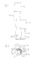
- FIGS. 4 and 5 show an alternative arrangement of the Four optical fibers shown with an adapter.
- This alternative Arrangement shows a further reduction in maximum cable cross-sectional area compared to the first Embodiment. 4, the adapters 4a up to 4d offset by the length of an adapter, in a row arranged one below the other.
- This arrangement results compared to Fig. 4 four adapter levels.
- the adapters 4a, 4b and 4c are in plan view arranged such that the adapters 4b and 4c in turn the Touch the optical fiber 2 of the adapter 4a.
- This second Adapter arrangement (Fig.
- the adapter 4d is below the three adapters 4a, 4b and 4c arranged so that he the three optical fibers 2 of three adapters 4a, 4b and 4c touched.
- This special Arrangement of the four adapters 4a-4d becomes a larger "total overlap area" - hatched areas in Fig. 5 - achieved, compared to the arrangement of FIGS. 2 and 3. Consequently is also the maximum cross-sectional area of the fiber optic cable 1 with adapters 4a-4d according to FIG. 5 smaller than that of the fiber optic cable 1 according to FIG. 3.
- optical fiber with the adapter of FIGS. 2-5 without a support element, without aramid yarn reinforcement and outer jacket are shown in practice are the optical fiber cables equipped with these and other cable components.
- the two embodiments with four adapters are used just to illustrate the many possibilities when arranging and moving adapters one Optical fiber cable end. They are limited to four Optical fiber with adapters, whereas commercially available Optical fiber cables between one and twelve optical fibers per cable. A transfer of the in the arrangement principle shown in both embodiments the adapter of an optical fiber cable with more or fewer individual optical fibers is possible analogously.
Landscapes
- Physics & Mathematics (AREA)
- General Physics & Mathematics (AREA)
- Optics & Photonics (AREA)
- Glass Compositions (AREA)
- Mechanical Coupling Of Light Guides (AREA)
- Communication Cables (AREA)
- Light Guides In General And Applications Therefor (AREA)
- Cable Accessories (AREA)
Description
- Fig. 1
- ein Ausführungsbeispiel eines Lichtwellenleiters mit Adapter;
- Fig. 2
- eine schematische Seitenansicht eines Ausführungsbeispiels mit vier Lichtwellenleitern mit Adaptern;
- Fig. 3
- eine Draufsicht von Fig. 2;
- Fig. 4
- eine schematische Seitenansicht eines zweiten Ausführungsbeispiels mit vier Lichtwellenleitern mit Adaptern; und
- Fig. 5
- eine Draufsicht von Fig. 4.
Claims (10)
- Lichtwellenleiter-Kabel (1) mit mindestens zwei Lichtwellenleitern (2), wobei die Lichtwellenleiter (2) an wenigstens einem Kabelende je einen Adapter (4) für eine Steckverbindung bzw. einen Stekker aufweisen, und die Adapter (4) in Querrichtung des Kabels (1) versetzt angeordnet sind, dadurch gekennzeichnet, daß die Adapter (4) auch in Längsrichtung des Kabels (1) versetzt sind und derart angeordnet sind, daß sich die Querschnittsflächen der Adapter, wenn das gestreckte Kabel in Längsrichtung betrachtet wird, zumindest teilweise überlappen.
- Lichtwellenleiter-Kabel nach Anspruch 1, dadurch gekennzeichnet, daß die Adapter (4) mit einem Durchmesser von max. 3 mm ausgebildet sind.
- Lichtwellenleiter-Kabel nach Anspruch 1 oder 2, dadurch gekennzeichnet, daß die Adapter benachbarter Lichtwellenleiter (2) um mindestens einen - der Ausdehnung eines Adapters in Längsrichtung des Kabels (1) entsprechenden - Betrag versetzt angeordnet sind.
- Lichtwellenleiter-Kabel nach einem der vorstehenden Ansprüche, dadurch gekennzeichnet, daß sich die versetzten Adapter (4) mehrerer Lichtwellenleiter (2) aneinander reihen.
- Lichtwellenleiter-Kabel nach einem der vorstehenden Ansprüche, dadurch gekennzeichnet, daß die Adapter (4) einen gekrümmten, insbesondere runden Querschnitt aufweisen.
- Lichtwellenleiter-Kabel nach einem der vorstehenden Ansprüche, dadurch gekennzeichnet, daß die Adapter (4) mit den Lichtwellenleitern (2) fest verbunden, insbesondere damit verklebt und/oder darauf unter Preßpassung aufgesetzt sind.
- Lichtwellenleiter-Kabel nach einem der vorstehenden Ansprüche, dadurch gekennzeichnet, daß die Adapter (4) mit unterschiedlichen Lichtwellenleiter-Steckern verbindbar sind.
- Lichtwellenleiter-Kabel nach Anspruch 7, dadurch gekennzeichnet, daß die Adapter (4) für Standard-, Duplex-, Hybrid-, ST- oder SC-Lichtwellenleiter-Stecker ausgelegt sind.
- Lichtwellenleiter-Kabel nach einem der vorstehenden Ansprüche, dadurch gekennzeichnet, daß ein Kabelstützelement, vorzugsweise aus GFK, zwischen den Lichtwellenleitern (2) eines Lichtwellenleiter-Kabels (1) angeordnet wird, insbesondere entlang dessen zentrischer Achse.
- Lichtwellenleiter-Kabel nach einem der Ansprüche 1 bis 8, dadurch gekennzeichnet, daß die Lichtwellenleiter (2) samt Adapter (4) von einer Aramidgarnarmierung, insbesondere Kevlar, und einem Außenmantel, insbesondere Kunststoff, z.B. PE, umgeben sind.
Applications Claiming Priority (2)
| Application Number | Priority Date | Filing Date | Title |
|---|---|---|---|
| DE9415713U | 1994-09-27 | ||
| DE9415713U DE9415713U1 (de) | 1994-09-27 | 1994-09-27 | Lichtwellenleiter-Kabel |
Publications (2)
| Publication Number | Publication Date |
|---|---|
| EP0704729A1 EP0704729A1 (de) | 1996-04-03 |
| EP0704729B1 true EP0704729B1 (de) | 1998-08-12 |
Family
ID=6914281
Family Applications (1)
| Application Number | Title | Priority Date | Filing Date |
|---|---|---|---|
| EP94118889A Expired - Lifetime EP0704729B1 (de) | 1994-09-27 | 1994-11-30 | Lichtwellenleiter-Kabel |
Country Status (4)
| Country | Link |
|---|---|
| EP (1) | EP0704729B1 (de) |
| AT (1) | ATE169745T1 (de) |
| DE (2) | DE9415713U1 (de) |
| ES (1) | ES2119949T3 (de) |
Citations (3)
| Publication number | Priority date | Publication date | Assignee | Title |
|---|---|---|---|---|
| EP0233805A2 (de) * | 1986-01-31 | 1987-08-26 | AT&T Corp. | Faseroptisches Kabel |
| EP0293183A2 (de) * | 1987-05-26 | 1988-11-30 | Minnesota Mining And Manufacturing Company | Verteilertafel für optische Fasern |
| EP0375168A1 (de) * | 1988-12-21 | 1990-06-27 | The Whitaker Corporation | Optischer Stecker |
Family Cites Families (9)
| Publication number | Priority date | Publication date | Assignee | Title |
|---|---|---|---|---|
| DE2461794C2 (de) * | 1974-12-30 | 1981-12-24 | Corning Glass Works, 14830 Corning, N.Y. | Optisches Faserbündel |
| FR2393329A1 (fr) * | 1977-05-31 | 1978-12-29 | Cables De Lyon Geoffroy Delore | Dispositif de raccordement global en bout de deux groupes de sept fibres optiques |
| DE2733100A1 (de) * | 1977-07-22 | 1979-02-08 | Messerschmitt Boelkow Blohm | Verfahren zur erzeugung eines lichtleiterbuendels |
| DE2835657A1 (de) * | 1978-08-14 | 1980-02-28 | Licentia Gmbh | Stecker fuer kabel mit mehreren lichtleitfasern |
| JPS5622403A (en) * | 1979-07-31 | 1981-03-03 | Matsushita Electric Works Ltd | Coupling method of optical fiber |
| JPS59805B2 (ja) * | 1979-09-05 | 1984-01-09 | 日本電信電話株式会社 | 光伝送用多極コネクタ |
| JPS6057807A (ja) * | 1983-09-09 | 1985-04-03 | Nissan Motor Co Ltd | 光フアイバコネクタ |
| DE3517388A1 (de) * | 1985-05-14 | 1986-11-20 | Allied Corp., Morristown, N.J. | Anschlussteil fuer ein faser-optisches kabel |
| US5117475A (en) * | 1991-04-29 | 1992-05-26 | General Electric Company | Fiber optic connector |
-
1994
- 1994-09-27 DE DE9415713U patent/DE9415713U1/de not_active Expired - Lifetime
- 1994-11-30 EP EP94118889A patent/EP0704729B1/de not_active Expired - Lifetime
- 1994-11-30 ES ES94118889T patent/ES2119949T3/es not_active Expired - Lifetime
- 1994-11-30 DE DE59406687T patent/DE59406687D1/de not_active Expired - Fee Related
- 1994-11-30 AT AT94118889T patent/ATE169745T1/de not_active IP Right Cessation
Patent Citations (3)
| Publication number | Priority date | Publication date | Assignee | Title |
|---|---|---|---|---|
| EP0233805A2 (de) * | 1986-01-31 | 1987-08-26 | AT&T Corp. | Faseroptisches Kabel |
| EP0293183A2 (de) * | 1987-05-26 | 1988-11-30 | Minnesota Mining And Manufacturing Company | Verteilertafel für optische Fasern |
| EP0375168A1 (de) * | 1988-12-21 | 1990-06-27 | The Whitaker Corporation | Optischer Stecker |
Also Published As
| Publication number | Publication date |
|---|---|
| ATE169745T1 (de) | 1998-08-15 |
| DE9415713U1 (de) | 1994-11-17 |
| DE59406687D1 (de) | 1998-09-17 |
| ES2119949T3 (es) | 1998-10-16 |
| EP0704729A1 (de) | 1996-04-03 |
Similar Documents
| Publication | Publication Date | Title |
|---|---|---|
| DE69120592T2 (de) | Kabelmodul | |
| EP0608517A1 (de) | Gehäuse für passive optische Komponenten | |
| DE60304071T2 (de) | Blockbasis mit baumstrukturiertem rillenfeld, vieladriger lichtwellenleiterblock mit baumstrukturierten rillenfeldern und verfahren des anordnens von lichtwellenleiterfeldern in diesem | |
| DE4142729C2 (de) | Nachrichtenkabel | |
| DE3911700A1 (de) | Optisches verbindungsstueck | |
| DE69212341T2 (de) | Lichtwellenleiterverteilungsanordnung | |
| EP0257706A2 (de) | Anordnung zur zugentlastenden Verbindung eines optischen Kabels mit einer Kupplungseinrichtung | |
| DE19613733C1 (de) | Verzweigungsanordnung für ein vieladriges Lichtwellenleiterkabel | |
| DE2718027A1 (de) | Verbinder fuer lichtleitkabel | |
| EP0704729A1 (de) | Lichtwellenleiter-Kabel | |
| DE19838351C2 (de) | Optisches Kabel und Kabelanordnung | |
| DE4214039C2 (de) | Vorrichtung zum Aufteilen von Lichtwellenleitern eines optischen Kabels | |
| EP0379126A2 (de) | Lichtwellenleiterkabel | |
| DE4211489A1 (de) | Optisches Übertragungselement | |
| EP0569679A1 (de) | Optisches Flachkabel | |
| WO2007065540A1 (de) | Einbauelement für ein kabelverzweigergehäuse | |
| EP0547323B1 (de) | LWL-Verbindungseinrichtung für eine Abzweigung und Verfahren zum Herstellen einer LWL-Verbindung an einer Abzweigung | |
| DE3301723C2 (de) | ||
| DE9105800U1 (de) | Kabelendeinrichtung für Lichtwellenleiterkabel | |
| EP1674907B1 (de) | Stecker für Lichtwellenleiter | |
| EP0515827A2 (de) | Abzweigmuffe für ein optisches Kabel | |
| WO2002014908A2 (de) | Vorkonfektioniertes lichtwellenleiter-kabel und verfahren zur vorkonfektionierung eines lichtwellenleiter-kabels | |
| DE4133372C2 (de) | Lichtwellenleiter-Verteilereinrichtung | |
| DE60121680T2 (de) | Lichtwellenleiter-Separator | |
| DE10154949A1 (de) | Lichtwellenleiterkabel |
Legal Events
| Date | Code | Title | Description |
|---|---|---|---|
| PUAI | Public reference made under article 153(3) epc to a published international application that has entered the european phase |
Free format text: ORIGINAL CODE: 0009012 |
|
| 17P | Request for examination filed |
Effective date: 19951130 |
|
| AK | Designated contracting states |
Kind code of ref document: A1 Designated state(s): AT BE CH DE ES GB IT LI NL PT |
|
| RAP1 | Party data changed (applicant data changed or rights of an application transferred) |
Owner name: EUROMICRON GMBH Owner name: DAETWYLER GMBH KABEL UND SYSTEME |
|
| 17Q | First examination report despatched |
Effective date: 19970207 |
|
| GRAG | Despatch of communication of intention to grant |
Free format text: ORIGINAL CODE: EPIDOS AGRA |
|
| GRAG | Despatch of communication of intention to grant |
Free format text: ORIGINAL CODE: EPIDOS AGRA |
|
| GRAH | Despatch of communication of intention to grant a patent |
Free format text: ORIGINAL CODE: EPIDOS IGRA |
|
| GRAH | Despatch of communication of intention to grant a patent |
Free format text: ORIGINAL CODE: EPIDOS IGRA |
|
| GRAA | (expected) grant |
Free format text: ORIGINAL CODE: 0009210 |
|
| AK | Designated contracting states |
Kind code of ref document: B1 Designated state(s): AT BE CH DE ES GB IT LI NL PT |
|
| REF | Corresponds to: |
Ref document number: 169745 Country of ref document: AT Date of ref document: 19980815 Kind code of ref document: T |
|
| REG | Reference to a national code |
Ref country code: CH Ref legal event code: NV Representative=s name: R. A. EGLI & CO. PATENTANWAELTE Ref country code: CH Ref legal event code: EP |
|
| REF | Corresponds to: |
Ref document number: 59406687 Country of ref document: DE Date of ref document: 19980917 |
|
| REG | Reference to a national code |
Ref country code: ES Ref legal event code: FG2A Ref document number: 2119949 Country of ref document: ES Kind code of ref document: T3 |
|
| GBT | Gb: translation of ep patent filed (gb section 77(6)(a)/1977) |
Effective date: 19981019 |
|
| REG | Reference to a national code |
Ref country code: PT Ref legal event code: SC4A Free format text: AVAILABILITY OF NATIONAL TRANSLATION Effective date: 19980831 |
|
| PLBE | No opposition filed within time limit |
Free format text: ORIGINAL CODE: 0009261 |
|
| 26N | No opposition filed | ||
| REG | Reference to a national code |
Ref country code: GB Ref legal event code: IF02 |
|
| PGFP | Annual fee paid to national office [announced via postgrant information from national office to epo] |
Ref country code: ES Payment date: 20041125 Year of fee payment: 11 |
|
| PG25 | Lapsed in a contracting state [announced via postgrant information from national office to epo] |
Ref country code: ES Free format text: LAPSE BECAUSE OF NON-PAYMENT OF DUE FEES Effective date: 20051201 |
|
| REG | Reference to a national code |
Ref country code: ES Ref legal event code: FD2A Effective date: 20051201 |
|
| PGFP | Annual fee paid to national office [announced via postgrant information from national office to epo] |
Ref country code: DE Payment date: 20071130 Year of fee payment: 14 |
|
| PGFP | Annual fee paid to national office [announced via postgrant information from national office to epo] |
Ref country code: NL Payment date: 20081120 Year of fee payment: 15 Ref country code: CH Payment date: 20081124 Year of fee payment: 15 |
|
| PGFP | Annual fee paid to national office [announced via postgrant information from national office to epo] |
Ref country code: PT Payment date: 20081120 Year of fee payment: 15 Ref country code: AT Payment date: 20081125 Year of fee payment: 15 |
|
| PGFP | Annual fee paid to national office [announced via postgrant information from national office to epo] |
Ref country code: BE Payment date: 20081202 Year of fee payment: 15 Ref country code: IT Payment date: 20081124 Year of fee payment: 15 |
|
| PGFP | Annual fee paid to national office [announced via postgrant information from national office to epo] |
Ref country code: GB Payment date: 20081121 Year of fee payment: 15 |
|
| PG25 | Lapsed in a contracting state [announced via postgrant information from national office to epo] |
Ref country code: DE Free format text: LAPSE BECAUSE OF NON-PAYMENT OF DUE FEES Effective date: 20090603 |
|
| BERE | Be: lapsed |
Owner name: *EUROMICRON G.M.B.H. Effective date: 20091130 Owner name: *DATWYLER G.M.B.H. KABEL UND SYSTEME Effective date: 20091130 |
|
| REG | Reference to a national code |
Ref country code: PT Ref legal event code: MM4A Free format text: LAPSE DUE TO NON-PAYMENT OF FEES Effective date: 20100531 |
|
| REG | Reference to a national code |
Ref country code: NL Ref legal event code: V1 Effective date: 20100601 |
|
| REG | Reference to a national code |
Ref country code: CH Ref legal event code: PL |
|
| GBPC | Gb: european patent ceased through non-payment of renewal fee |
Effective date: 20091130 |
|
| PG25 | Lapsed in a contracting state [announced via postgrant information from national office to epo] |
Ref country code: PT Free format text: LAPSE BECAUSE OF NON-PAYMENT OF DUE FEES Effective date: 20100531 |
|
| PG25 | Lapsed in a contracting state [announced via postgrant information from national office to epo] |
Ref country code: AT Free format text: LAPSE BECAUSE OF NON-PAYMENT OF DUE FEES Effective date: 20091130 |
|
| PG25 | Lapsed in a contracting state [announced via postgrant information from national office to epo] |
Ref country code: NL Free format text: LAPSE BECAUSE OF NON-PAYMENT OF DUE FEES Effective date: 20100601 Ref country code: LI Free format text: LAPSE BECAUSE OF NON-PAYMENT OF DUE FEES Effective date: 20091130 Ref country code: CH Free format text: LAPSE BECAUSE OF NON-PAYMENT OF DUE FEES Effective date: 20091130 Ref country code: BE Free format text: LAPSE BECAUSE OF NON-PAYMENT OF DUE FEES Effective date: 20091130 |
|
| PG25 | Lapsed in a contracting state [announced via postgrant information from national office to epo] |
Ref country code: GB Free format text: LAPSE BECAUSE OF NON-PAYMENT OF DUE FEES Effective date: 20091130 |
|
| PG25 | Lapsed in a contracting state [announced via postgrant information from national office to epo] |
Ref country code: IT Free format text: LAPSE BECAUSE OF NON-PAYMENT OF DUE FEES Effective date: 20091130 |