EP0703108B1 - Vitrage avec cadre profilé particulièrement vitrage automobile et sa méthode de pose - Google Patents
Vitrage avec cadre profilé particulièrement vitrage automobile et sa méthode de pose Download PDFInfo
- Publication number
- EP0703108B1 EP0703108B1 EP95117789A EP95117789A EP0703108B1 EP 0703108 B1 EP0703108 B1 EP 0703108B1 EP 95117789 A EP95117789 A EP 95117789A EP 95117789 A EP95117789 A EP 95117789A EP 0703108 B1 EP0703108 B1 EP 0703108B1
- Authority
- EP
- European Patent Office
- Prior art keywords
- glazing
- lip
- frame
- profiled frame
- seal
- Prior art date
- Legal status (The legal status is an assumption and is not a legal conclusion. Google has not performed a legal analysis and makes no representation as to the accuracy of the status listed.)
- Expired - Lifetime
Links
Images


Classifications
-
- B—PERFORMING OPERATIONS; TRANSPORTING
- B29—WORKING OF PLASTICS; WORKING OF SUBSTANCES IN A PLASTIC STATE IN GENERAL
- B29D—PRODUCING PARTICULAR ARTICLES FROM PLASTICS OR FROM SUBSTANCES IN A PLASTIC STATE
- B29D99/00—Subject matter not provided for in other groups of this subclass
- B29D99/0053—Producing sealings
-
- B—PERFORMING OPERATIONS; TRANSPORTING
- B29—WORKING OF PLASTICS; WORKING OF SUBSTANCES IN A PLASTIC STATE IN GENERAL
- B29C—SHAPING OR JOINING OF PLASTICS; SHAPING OF MATERIAL IN A PLASTIC STATE, NOT OTHERWISE PROVIDED FOR; AFTER-TREATMENT OF THE SHAPED PRODUCTS, e.g. REPAIRING
- B29C43/00—Compression moulding, i.e. applying external pressure to flow the moulding material; Apparatus therefor
- B29C43/02—Compression moulding, i.e. applying external pressure to flow the moulding material; Apparatus therefor of articles of definite length, i.e. discrete articles
- B29C43/20—Making multilayered or multicoloured articles
- B29C43/203—Making multilayered articles
- B29C43/206—Making multilayered articles by pressing the material between two preformed layers, e.g. deformable layers
-
- B—PERFORMING OPERATIONS; TRANSPORTING
- B29—WORKING OF PLASTICS; WORKING OF SUBSTANCES IN A PLASTIC STATE IN GENERAL
- B29C—SHAPING OR JOINING OF PLASTICS; SHAPING OF MATERIAL IN A PLASTIC STATE, NOT OTHERWISE PROVIDED FOR; AFTER-TREATMENT OF THE SHAPED PRODUCTS, e.g. REPAIRING
- B29C48/00—Extrusion moulding, i.e. expressing the moulding material through a die or nozzle which imparts the desired form; Apparatus therefor
- B29C48/15—Extrusion moulding, i.e. expressing the moulding material through a die or nozzle which imparts the desired form; Apparatus therefor incorporating preformed parts or layers, e.g. extrusion moulding around inserts
- B29C48/154—Coating solid articles, i.e. non-hollow articles
- B29C48/155—Partial coating thereof
-
- B—PERFORMING OPERATIONS; TRANSPORTING
- B29—WORKING OF PLASTICS; WORKING OF SUBSTANCES IN A PLASTIC STATE IN GENERAL
- B29C—SHAPING OR JOINING OF PLASTICS; SHAPING OF MATERIAL IN A PLASTIC STATE, NOT OTHERWISE PROVIDED FOR; AFTER-TREATMENT OF THE SHAPED PRODUCTS, e.g. REPAIRING
- B29C53/00—Shaping by bending, folding, twisting, straightening or flattening; Apparatus therefor
- B29C53/16—Straightening or flattening
-
- B—PERFORMING OPERATIONS; TRANSPORTING
- B29—WORKING OF PLASTICS; WORKING OF SUBSTANCES IN A PLASTIC STATE IN GENERAL
- B29C—SHAPING OR JOINING OF PLASTICS; SHAPING OF MATERIAL IN A PLASTIC STATE, NOT OTHERWISE PROVIDED FOR; AFTER-TREATMENT OF THE SHAPED PRODUCTS, e.g. REPAIRING
- B29C66/00—General aspects of processes or apparatus for joining preformed parts
- B29C66/01—General aspects dealing with the joint area or with the area to be joined
- B29C66/03—After-treatments in the joint area
- B29C66/032—Mechanical after-treatments
- B29C66/0324—Reforming or reshaping the joint, e.g. folding over
-
- B—PERFORMING OPERATIONS; TRANSPORTING
- B29—WORKING OF PLASTICS; WORKING OF SUBSTANCES IN A PLASTIC STATE IN GENERAL
- B29C—SHAPING OR JOINING OF PLASTICS; SHAPING OF MATERIAL IN A PLASTIC STATE, NOT OTHERWISE PROVIDED FOR; AFTER-TREATMENT OF THE SHAPED PRODUCTS, e.g. REPAIRING
- B29C66/00—General aspects of processes or apparatus for joining preformed parts
- B29C66/01—General aspects dealing with the joint area or with the area to be joined
- B29C66/05—Particular design of joint configurations
- B29C66/10—Particular design of joint configurations particular design of the joint cross-sections
- B29C66/11—Joint cross-sections comprising a single joint-segment, i.e. one of the parts to be joined comprising a single joint-segment in the joint cross-section
- B29C66/112—Single lapped joints
- B29C66/1122—Single lap to lap joints, i.e. overlap joints
-
- B—PERFORMING OPERATIONS; TRANSPORTING
- B29—WORKING OF PLASTICS; WORKING OF SUBSTANCES IN A PLASTIC STATE IN GENERAL
- B29C—SHAPING OR JOINING OF PLASTICS; SHAPING OF MATERIAL IN A PLASTIC STATE, NOT OTHERWISE PROVIDED FOR; AFTER-TREATMENT OF THE SHAPED PRODUCTS, e.g. REPAIRING
- B29C66/00—General aspects of processes or apparatus for joining preformed parts
- B29C66/50—General aspects of joining tubular articles; General aspects of joining long products, i.e. bars or profiled elements; General aspects of joining single elements to tubular articles, hollow articles or bars; General aspects of joining several hollow-preforms to form hollow or tubular articles
- B29C66/51—Joining tubular articles, profiled elements or bars; Joining single elements to tubular articles, hollow articles or bars; Joining several hollow-preforms to form hollow or tubular articles
- B29C66/53—Joining single elements to tubular articles, hollow articles or bars
- B29C66/534—Joining single elements to open ends of tubular or hollow articles or to the ends of bars
- B29C66/5346—Joining single elements to open ends of tubular or hollow articles or to the ends of bars said single elements being substantially flat
-
- B—PERFORMING OPERATIONS; TRANSPORTING
- B29—WORKING OF PLASTICS; WORKING OF SUBSTANCES IN A PLASTIC STATE IN GENERAL
- B29C—SHAPING OR JOINING OF PLASTICS; SHAPING OF MATERIAL IN A PLASTIC STATE, NOT OTHERWISE PROVIDED FOR; AFTER-TREATMENT OF THE SHAPED PRODUCTS, e.g. REPAIRING
- B29C67/00—Shaping techniques not covered by groups B29C39/00 - B29C65/00, B29C70/00 or B29C73/00
-
- B—PERFORMING OPERATIONS; TRANSPORTING
- B29—WORKING OF PLASTICS; WORKING OF SUBSTANCES IN A PLASTIC STATE IN GENERAL
- B29C—SHAPING OR JOINING OF PLASTICS; SHAPING OF MATERIAL IN A PLASTIC STATE, NOT OTHERWISE PROVIDED FOR; AFTER-TREATMENT OF THE SHAPED PRODUCTS, e.g. REPAIRING
- B29C70/00—Shaping composites, i.e. plastics material comprising reinforcements, fillers or preformed parts, e.g. inserts
- B29C70/68—Shaping composites, i.e. plastics material comprising reinforcements, fillers or preformed parts, e.g. inserts by incorporating or moulding on preformed parts, e.g. inserts or layers, e.g. foam blocks
- B29C70/74—Moulding material on a relatively small portion of the preformed part, e.g. outsert moulding
- B29C70/76—Moulding on edges or extremities of the preformed part
- B29C70/763—Moulding on edges or extremities of the preformed part the edges being disposed in a substantial flat plane
-
- B—PERFORMING OPERATIONS; TRANSPORTING
- B60—VEHICLES IN GENERAL
- B60J—WINDOWS, WINDSCREENS, NON-FIXED ROOFS, DOORS, OR SIMILAR DEVICES FOR VEHICLES; REMOVABLE EXTERNAL PROTECTIVE COVERINGS SPECIALLY ADAPTED FOR VEHICLES
- B60J10/00—Sealing arrangements
- B60J10/70—Sealing arrangements specially adapted for windows or windscreens
-
- C—CHEMISTRY; METALLURGY
- C03—GLASS; MINERAL OR SLAG WOOL
- C03C—CHEMICAL COMPOSITION OF GLASSES, GLAZES OR VITREOUS ENAMELS; SURFACE TREATMENT OF GLASS; SURFACE TREATMENT OF FIBRES OR FILAMENTS MADE FROM GLASS, MINERALS OR SLAGS; JOINING GLASS TO GLASS OR OTHER MATERIALS
- C03C27/00—Joining pieces of glass to pieces of other inorganic material; Joining glass to glass other than by fusing
- C03C27/04—Joining glass to metal by means of an interlayer
- C03C27/048—Joining glass to metal by means of an interlayer consisting of an adhesive specially adapted for that purpose
-
- B—PERFORMING OPERATIONS; TRANSPORTING
- B29—WORKING OF PLASTICS; WORKING OF SUBSTANCES IN A PLASTIC STATE IN GENERAL
- B29C—SHAPING OR JOINING OF PLASTICS; SHAPING OF MATERIAL IN A PLASTIC STATE, NOT OTHERWISE PROVIDED FOR; AFTER-TREATMENT OF THE SHAPED PRODUCTS, e.g. REPAIRING
- B29C48/00—Extrusion moulding, i.e. expressing the moulding material through a die or nozzle which imparts the desired form; Apparatus therefor
- B29C48/03—Extrusion moulding, i.e. expressing the moulding material through a die or nozzle which imparts the desired form; Apparatus therefor characterised by the shape of the extruded material at extrusion
- B29C48/12—Articles with an irregular circumference when viewed in cross-section, e.g. window profiles
-
- B—PERFORMING OPERATIONS; TRANSPORTING
- B29—WORKING OF PLASTICS; WORKING OF SUBSTANCES IN A PLASTIC STATE IN GENERAL
- B29C—SHAPING OR JOINING OF PLASTICS; SHAPING OF MATERIAL IN A PLASTIC STATE, NOT OTHERWISE PROVIDED FOR; AFTER-TREATMENT OF THE SHAPED PRODUCTS, e.g. REPAIRING
- B29C65/00—Joining or sealing of preformed parts, e.g. welding of plastics materials; Apparatus therefor
- B29C65/78—Means for handling the parts to be joined, e.g. for making containers or hollow articles, e.g. means for handling sheets, plates, web-like materials, tubular articles, hollow articles or elements to be joined therewith; Means for discharging the joined articles from the joining apparatus
- B29C65/7841—Holding or clamping means for handling purposes
- B29C65/7847—Holding or clamping means for handling purposes using vacuum to hold at least one of the parts to be joined
-
- B—PERFORMING OPERATIONS; TRANSPORTING
- B29—WORKING OF PLASTICS; WORKING OF SUBSTANCES IN A PLASTIC STATE IN GENERAL
- B29C—SHAPING OR JOINING OF PLASTICS; SHAPING OF MATERIAL IN A PLASTIC STATE, NOT OTHERWISE PROVIDED FOR; AFTER-TREATMENT OF THE SHAPED PRODUCTS, e.g. REPAIRING
- B29C66/00—General aspects of processes or apparatus for joining preformed parts
- B29C66/70—General aspects of processes or apparatus for joining preformed parts characterised by the composition, physical properties or the structure of the material of the parts to be joined; Joining with non-plastics material
- B29C66/71—General aspects of processes or apparatus for joining preformed parts characterised by the composition, physical properties or the structure of the material of the parts to be joined; Joining with non-plastics material characterised by the composition of the plastics material of the parts to be joined
-
- B—PERFORMING OPERATIONS; TRANSPORTING
- B29—WORKING OF PLASTICS; WORKING OF SUBSTANCES IN A PLASTIC STATE IN GENERAL
- B29L—INDEXING SCHEME ASSOCIATED WITH SUBCLASS B29C, RELATING TO PARTICULAR ARTICLES
- B29L2031/00—Other particular articles
- B29L2031/26—Sealing devices, e.g. packaging for pistons or pipe joints
-
- B—PERFORMING OPERATIONS; TRANSPORTING
- B29—WORKING OF PLASTICS; WORKING OF SUBSTANCES IN A PLASTIC STATE IN GENERAL
- B29L—INDEXING SCHEME ASSOCIATED WITH SUBCLASS B29C, RELATING TO PARTICULAR ARTICLES
- B29L2031/00—Other particular articles
- B29L2031/30—Vehicles, e.g. ships or aircraft, or body parts thereof
- B29L2031/3055—Cars
Definitions
- the invention relates to glazing intended for bonding on the sheet metal of a window opening, in particular glazing automobile.
- This is equipped in particular by extrusion of a suitable polymer on the surface of the glass opposite the sheet, a profiled frame which, after polymerization, will serve thanks to an appendage, protective element and centering during taking the glue fixing the glazing.
- Automotive glass is in its today majority glued directly to the bay sheet in the body. It turned out to be interesting to prepare the glazing with a view to mounting it by a preliminary work phase for example in the factory where the glazing was product. It is thus fitted with an extrusion profile on the glazing which, after polymerization, will cooperate with the glazing and the bead of glue intended for the final gluing of the glazing. In proceeding in this way we limit, when mounting the windshield, cleaning and priming operations of the glazing. Overall the preparation and assembly operation glazing is thus more economical. This process is described for example in patent EP-A-0 121 481.
- EP-A-0 345 134 which constitutes a state of the art in title of Article 54 (3) and (4) EPC for the states BE, CH, DE, ES, FR, GB, IT, LI, LU, NL, SE, AT describes a process for manufacturing ready-to-install glazing intended to be glued to the frame of a vehicle body bay.
- two partial beads of glue are deposited simultaneously or immediately one after the other in a single operation of coextrusion.
- the mass of glue forming the first bead hardens in a while relatively short, while the mass of glue forming the other bead remains plastically deformable and adhesive for a sufficient time until mounting on the vehicle.
- the first bead can be provided with a sealing lip facilitating the pose.
- the invention sets out to modify a glazing unit fitted with a profiled frame of the type previously described so that the centering and the support of the glazing during its installation and the setting of the adhesive is carried out without intervention by other means.
- glazing particularly automotive glazing, intended for direct bonding within the frame of a window is fitted with a profiled frame, deposited on an opaque layer on the surface of the glass opposite sheet metal, the profiled frame having once the characteristics of a elastomer and being intended to support a bead of laying adhesive, the bead installation adhesive being subsequently deposited on the glazing while the frame profile is already hardened, wherein said profiled frame has an appendage which is a lip which projects beyond the glazing, substantially parallel to the surface of the glass, the lip having a dimensioning and / or a coefficient of friction as well as a stiffness such as it realizes the centering of the glazing and / or its support and / or that it supports the reaction force which must be exercised for the duration of the adhesive bead setting.
- the lip has a length of between 5 and 10 mm.
- glazing 1 is a windshield, it is placed in the bay of a bodywork automobile. This bay is limited on the one hand by the fixing sheet 2 which is parallel to the surface of the glazing, and on the other hand by the sheet 4 whose surface is perpendicular to the surface of the glazing.
- Glazing 1 is represented in the form of a monolithic glass sheet but it is obvious that it can be as well a laminated glazing. Glazing 1 is equipped at its periphery on the surface opposite to the fixing plate 2 of a layer opaque 5 which, for example, consists of a baked enamel hot. The function of this layer 5 is to prevent can see through the glass, from the outside, the gluing elements and at the same time protect the glue against ultraviolet.
- Glazing 1 is equipped on its surface opposite to the sheet fixing 2 of a profiled frame 8. This is made of a polymer which, when finished, has the characteristics of an elastomer. Profile frame 8 adheres to the opaque layer 5. The profiled frame 8 has a lip peripheral 10. This lip 10 has before the introduction glazing 1 in the bay a straight shape. She is at this moment substantially parallel to the surface of the glazing and protrudes from its periphery 3 by approximately 5 to 10 mm.
- the lip 10 deforms when the glazing in the bay and undergoes a backward fold positioning along its entire length along the sheet 4 which is located opposite edge 3 of the glazing. In this way when the glazing is introduced into the bay, it is automatically centered and we see a groove appear 12 of constant width all around.
- lip 10 is used in the lower part of glazing 1 for support its weight in such a way that no wedging is no longer necessary during the time between the establishment of the glazing and setting the glue.
- the lip 10 is used to close the groove 12 and it makes it waterproof.
- the dimensioning of the lip 10, that is to say the length and thickness of its section must be determined from so that the functions to be fulfilled by lip 10 the are as best as possible.
- FIG. 2 thus represents a section of glazing 1 placed in the window bay of the body 7.
- the bead of glue 13 instead of being in contact on the side of the glazing 1, that with the profile 8, is, in plus, in direct contact with glazing 1 or more precisely with the opaque layer 5.
- An adhesion primer 6 can be intended to favor the attachment of the bead of glue 13 on glazing.
- FIG. 3 A variant of this configuration is shown in section on FIG. 3. We see at 9 a second part of the peripheral profile whose role is to limit expansion glue 13. The other elements including the opaque frame 5 remain the same as in FIG. 2.
- the connection between the glazing itself and / or the frame profile 8 on the one hand, which equips glazing 1 at the time of its installation and on the other hand the fixing plate 2 is made as we saw it with the bead of glue 13.
- the glue is composed of a polymer which is designed to adhere firmly and permanent in frame 8 and possibly in glass or layer 5. This will be for example a one-component polyurethane polymerizes thanks to the humidity of the air.
- the pressure that must be exercised for the duration of the cord's grip glue 13 between the glazing and the fixing plate 2 is also ensured by the lip 10 of the profiled frame 8. It has a high coefficient of friction and its relative stiffness allows it to compensate for the reaction force exerted by the bead of glue 13.
- the manufacturing of the profiled frame 8 is done in a way known per se by extrusion of a suitable polymer which adheres to the glazing.
- a suitable polymer which adheres to the glazing.
- Such polymers suitable for manufacture of a profiled frame are for example polyurethanes to a component in pasty form which transform under the influence of air humidity into high modulus elastomer.
- Polymer systems of this kind are described for example in American patent US-A-3,779 794. It is also possible to use systems with two components like those described in patents European EP-A-0083797 or EP-A-0024501.
- priming layers such as layer 6 according to known methods.
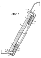
- the profiled frame 8 on the glazing we begins as shown in figure 2 by filing the glazing on a support frame 15 so that it is in horizontal position. I1 is fixed in this position by suitable means, for example suction cups. We then move the extrusion head along the edge of the glazing. This operation is preferably carried out by a programmed robot Consequently.
- the extrusion head has a nozzle 16 which is applied to the glass and moves in the direction of the arrow F.
- the nozzle 16 has on its rear face 17 a 18 calibrated opening. This provides profile 8 with the shape desired.
- the stability of the shape of the lip 10 which is generated by the extrusion nozzle over a length L is such that lip 10 keeps its shape and direction substantially horizontal without needing to be supported.
- the punch 25 is inclined at an angle ⁇ relative to the glazing then is moved down in this position until its edge 26 touches the surface of the glass. I1 then begins a rotational movement around this edge until it comes into contact with the glass sheet and the base 23. This produces the profiled frame including its lip 10 takes the desired shape at the location of the profile connection. The irregularity is then removed.
- the upper part of the foot 23 has a shape 29 which corresponds to the thickness of glazing 1 and which follows the part lower lip 10.
- the punch 25 also has a precise form 30 which corresponds to the upper limit of the profile 8 and lip 10. The translational movement and tilting undergoes the punch 25 to fill the possible gaps in the profile and evacuate excess materials in the extension of the lip 10 through the slot 32. After polymerization of the elastomer, the excess of material can be deburred at the end of the lip 10.
- the sheets 33, 34 are made of a material of which the surface has non-stick properties compared to polymer material of profile 8. Good results have been obtained with thin sheets of polyester or polyethylene. In the event that the polymer of the profiled frame 8 polymerizes in air humidity, sheets 33 and 34 have sufficient permeability to the water vapour. Eventually, it will be necessary to create a determined porosity or even piercing microperforations.
- the sheets 34, 35 also give the lip 10 a additional rigidity during setting. Excess material polymerizable is removed during the grinding process as we have already seen, towards the extension lip 10 and escapes as a thin layer between the two sheets 33, 34 where it will harden in the form a burr 41 which extends beyond the edge 40 of the lip 10 (figure 7). This burr 41 will be like sheets 33 and 34, cut and separated from profile 8 after polymerization. This operation gives the connection area an appearance neat to the lip 10 of the profiled frame 8. Finally tears off the remaining sheets 33, 34 to separate them from the profile 8 and lip 10.
- Foot 43 has a constitution which is similar to that of the foot 23 of FIG. 4.
- the foot is connected by a guide rod 44, just like the punch 46, to a tool holder not shown.
- Foot 43 is here too equipped on its upper surface with perforations. These are also connected to a distributor nozzle which is in communication through a hose 45 with a pump which can create depression.
- the punch 46 consists of two parts: the first 47 which has a corresponding reference surface 48 to the section of the profiled frame above glass, and a second part 49 also equipped with a calibrated surface 50 intended to conform the lip 10.
- the two parts, the first 47 thanks to the guide rod 51, and the second 49 thanks to the rod 52 can be operated independently of each other.
- the plastic film that goes here too be inserted between the punch and the profiled frame is set place both on the shapeless joint and on surfaces next to glazing 1 and foot 43. So, part 47 of punch moves first and comes to marry the part upper section 8 located above the glazing 1. Finally, part 49 of the same punch in turn corrects the lip shape 10.
- the embodiments of the invention presented here relate to the windshield of a motor vehicle.
- the invention is equally valid under the same conditions for any glazing such as glasses rear window or door, quarter, tailgate, roof or headlight protection.
- the method of the invention is also suitable for all fields where a glazing must be fixed by gluing inside a frame. In the transport sector, this will be the case for example railway or caravan glazing but the applications in the field of building, in that of furniture, or even appliances or appliances are also to be considered.
Description
- on dépose sur la couche opaque une matière polymère sous forme d'un cadre profilé comportant un appendice qui est une lèvre qui déborde du vitrage, sensiblement parallèle à la surface du verre, et
- on laisse durcir toute la matière formant le cadre.
- figure 1 : vitrage en position dans une baie et en coupe,
- figure 2 et figure 3 : exemples de vitrages conformes à EP-B-0 611 672,
- figure 4 : fabrication du cadre profilé grâce à une buse d'extrusion,
- figure 5 : la zone de transition du cadre profilé après le retrait de la buse d'extrusion,
- figure 6 : la rectification par pressage de la zone de transition grâce à un outil,
- figure 7 : la zone de transition du cadre profilé après la phase de pressage et,
- figure 8: une variante de l'outil de pressage .
Claims (6)
- Procédé de pose d'un vitrage (1) dans le cadre d'une baie (7), en particulier d'une automobile, par collage, procédé qui comporte une phase préliminaire d'extrusion sur le vitrage d'un cadre profilé (8) possédant un appendice qui servira d'élément de protection et qui est réalisé en un polymère qui, une fois terminé, possède les caractéristiques d'un élastomère, le procédé comportant ensuite une phase de dépôt au voisinage du cadre durci, d'un cordon de colle (13) destiné au collage final du vitrage, le cordon de colle (13) n'étant en contact du côté du vitrage qu'avec le profilé (8), le procédé comportant enfin une phase de mise en place du vitrage dans la baie, caractérisé en ce que le cadre profilé comporte une lèvre périphérique (10) qui possède avant l'introduction dans la baie une forme droite, qui est sensiblement parallèle à la surface du vitrage, qui se déforme au moment de l'introduction du vitrage dans la baie et qui subit une pliure vers l'arrière de telle sorte que, lorsque le vitrage est introduit dans la baie, il se trouve automatiquement centré.
- Procédé selon la revendication 1, caractérisé en ce que, en partie basse du vitrage, c'est la lèvre qui support le poids du vitrage.
- Procédé selon la revendication 1 ou 2, caractérisé en ce que la lèvre (10) possède un coefficient de frottement et une raideur tels qu'elle compense la force de réaction exercée par le cordon de colle (13) pendant le temps qui sépare la mise en place du vitrage et la prise de la colle.
- Vitrage, particulièrement vitrage automobile, destiné au collage direct dans une baie, équipé d'un cadre profilé (8) déposé sur une couche opaque (5) de la surface de verre en face de la tôle, le cadre profilé possédant une fois terminé les caractéristiques d'un élastomère et étant destiné à supporter un cordon de colle de pose (13), le cordon de colle (13) étant déposé ultérieurement sur le vitrage alors que le cadre profilé (8) est déjà durci, caractérisé en ce que ledit cadre profilé comporte un appendice qui est une lèvre (10), qui déborde du vitrage (1), sensiblement parallèle à la surface du verre, la lèvre (10) possédant un dimensionnement et/ou un coefficient de frottement ainsi qu'une raideur tels qu'elle réalise le centrage du vitrage et/ou son support et/ou qu'elle supporte la force de réaction qui doit être exercée pendant la durée de prise du cordon de colle (13).
- Vitrage selon la revendication 4, caractérisé en ce que la lèvre (10) déborde de la périphérie du vitrage d'environ 5 à 10 mm.
- Procédé de fabrication d'un vitrage selon la revendication 4 ou 5, dans lequel :on dépose sur la couche opaque (5) une matière polymère sous forme d'un cadre profilé (8) comportant un appendice qui est une lèvre (10) qui déborde du vitrage, sensiblement parallèle à la surface du verre et,on laisse durcir toute la matière formant le cadre.
Applications Claiming Priority (6)
| Application Number | Priority Date | Filing Date | Title |
|---|---|---|---|
| DE3930414A DE3930414C2 (de) | 1989-09-12 | 1989-09-12 | Verfahren und Vorrichtung zur Herstellung einer für die Direktverklebung mit dem Befestigungsflansch einer Fensteröffnung vorgesehenen Glasscheibe |
| DE3930414 | 1989-09-12 | ||
| US07/531,191 US5095669A (en) | 1989-12-13 | 1990-05-31 | Spacer for windshield bracket |
| US531191 | 1990-05-31 | ||
| EP90402445A EP0421833B2 (fr) | 1989-09-12 | 1990-09-06 | Vitrage avec cadre profilé particulierement vitrage automobile ainsi que le procédé et le dispositif pour la fabrication d'un tel vitrage |
| EP94105771A EP0611672B1 (fr) | 1989-09-12 | 1990-09-06 | Vitrage avec cadre profile particulierement vitrage automobile |
Related Parent Applications (3)
| Application Number | Title | Priority Date | Filing Date |
|---|---|---|---|
| EP94105771A Division EP0611672B1 (fr) | 1989-09-12 | 1990-09-06 | Vitrage avec cadre profile particulierement vitrage automobile |
| EP90402445.2 Division | 1990-09-06 | ||
| EP94105771.3 Division | 1990-09-06 |
Publications (2)
| Publication Number | Publication Date |
|---|---|
| EP0703108A1 EP0703108A1 (fr) | 1996-03-27 |
| EP0703108B1 true EP0703108B1 (fr) | 2001-08-01 |
Family
ID=25885068
Family Applications (3)
| Application Number | Title | Priority Date | Filing Date |
|---|---|---|---|
| EP94105771A Expired - Lifetime EP0611672B1 (fr) | 1989-09-12 | 1990-09-06 | Vitrage avec cadre profile particulierement vitrage automobile |
| EP95117789A Expired - Lifetime EP0703108B1 (fr) | 1989-09-12 | 1990-09-06 | Vitrage avec cadre profilé particulièrement vitrage automobile et sa méthode de pose |
| EP90402445A Expired - Lifetime EP0421833B2 (fr) | 1989-09-12 | 1990-09-06 | Vitrage avec cadre profilé particulierement vitrage automobile ainsi que le procédé et le dispositif pour la fabrication d'un tel vitrage |
Family Applications Before (1)
| Application Number | Title | Priority Date | Filing Date |
|---|---|---|---|
| EP94105771A Expired - Lifetime EP0611672B1 (fr) | 1989-09-12 | 1990-09-06 | Vitrage avec cadre profile particulierement vitrage automobile |
Family Applications After (1)
| Application Number | Title | Priority Date | Filing Date |
|---|---|---|---|
| EP90402445A Expired - Lifetime EP0421833B2 (fr) | 1989-09-12 | 1990-09-06 | Vitrage avec cadre profilé particulierement vitrage automobile ainsi que le procédé et le dispositif pour la fabrication d'un tel vitrage |
Country Status (6)
| Country | Link |
|---|---|
| EP (3) | EP0611672B1 (fr) |
| AT (3) | ATE163392T1 (fr) |
| DE (3) | DE69032073T2 (fr) |
| DK (3) | DK0611672T3 (fr) |
| ES (3) | ES2070291T5 (fr) |
| FI (1) | FI109343B (fr) |
Families Citing this family (25)
| Publication number | Priority date | Publication date | Assignee | Title |
|---|---|---|---|---|
| US5384995A (en) | 1989-09-12 | 1995-01-31 | St. Gobain Vitrage International | Spacer for windshield bracket |
| US5411696A (en) | 1990-12-27 | 1995-05-02 | Tokai Kogyo Kabushiki Kaisha | Process of making a panel unit |
| DE4123256C1 (fr) * | 1991-07-13 | 1992-10-08 | Saint Gobain Vitrage | |
| DE4123588A1 (de) * | 1991-07-17 | 1993-01-21 | Ver Glaswerke Gmbh | Verfahren und vorrichtung zur herstellung eines fahrzeugfensters |
| DE4133662A1 (de) * | 1991-10-11 | 1993-04-15 | Ver Glaswerke Gmbh | Mit einem einbaurahmen aus einem elastomer vorgeruestete glasscheibe |
| IT1263204B (it) * | 1992-01-28 | 1996-08-05 | Siv Soc Italiana Vetro | Procedimento e dispositivo per la giunzione di una guarnizione di bordo su un vetro. |
| DE69321649T2 (de) * | 1992-04-28 | 1999-04-15 | Asahi Glass Co Ltd | Verfahren zur Herstellung von Fensterglas mit Kunststoffrahmen |
| DE4232554C1 (de) * | 1992-09-29 | 1994-01-05 | Ver Glaswerke Gmbh | Verfahren zur Herstellung einer mit einem angeformten Rahmen aus einem thermoplastischen Polymer versehenen Glasscheibe und Vorrichtung zur Durchführung des Verfahrens |
| EP0785058B1 (fr) * | 1993-01-16 | 2002-06-05 | Saint-Gobain Glass France | Procédé et dispositif pour la fabrication d'un vitrage automobile prééquipé pour le collage dans une baie |
| DE4404348A1 (de) * | 1994-02-11 | 1995-08-17 | Fritz Richard Gmbh & Co Kg | Verfahren für die Herstellung und den Einbau einer Glasscheibe mit Rahmen, insbesondere an einem Fahrzeugteil |
| DK0679546T3 (da) * | 1994-04-20 | 1997-01-13 | Henniges Elastomer Kunststoff | Karrosserivindue til motorkøretøjer |
| DE4421299C2 (de) * | 1994-06-17 | 1996-04-11 | Sekurit Saint Gobain Deutsch | Verfahren und Vorrichtung zum Nachformen eines an einen Gegenstand anextrudierten Profilstrangs |
| DE4445258C2 (de) * | 1994-12-19 | 1996-10-02 | Sekurit Saint Gobain Deutsch | Verfahren und Vorrichtung zum Nachformen eines an einen Gegenstand anextrudierten Profilstrangs |
| IT1283895B1 (it) * | 1996-01-25 | 1998-05-07 | Tai Tecnologia Automazione Inn | Metodo ed apparecchiatura per modellare tratti di guarnizione realizzate per estrusione di un fluido viscoso all'atto del deposito |
| DE19604397C1 (de) * | 1996-02-07 | 1997-07-31 | Sekurit Saint Gobain Deutsch | Vorrichtung zum Anextrudieren eines rahmenartigen Profilstrangs an eine Glasscheibe |
| DE19619356A1 (de) * | 1996-05-14 | 1997-11-20 | Flachglas Ag | Glaseinheit mit einer Optobeschichtung |
| DE19721566B4 (de) * | 1996-06-04 | 2014-08-28 | Volkswagen Ag | Verfahren zur Herstellung eines Scheibenkörpers mit einem durch Umspritzung angeformten Rahmen aus weichelastischem Material |
| DE19632149C1 (de) * | 1996-08-09 | 1998-02-05 | Sekurit Saint Gobain Deutsch | Formstempel zum Nachformen eines an einen Gegenstand anextrudierten Profilstrangs |
| FR2757093B1 (fr) * | 1996-12-12 | 1999-01-08 | Saint Gobain Vitrage | Procede de rectification du chant d'un intercalaire assemblant deux substrats |
| FR2770212B1 (fr) * | 1997-10-29 | 1999-11-26 | Eurokera | Plaque en materiau verrier destinee a etre fixee dans un cadre |
| DE19843843C2 (de) * | 1998-09-24 | 2001-08-30 | Saint Gobain Sekurit D Gmbh | Fensterscheibe mit einem eine Spaltabdeckung umfassenden Profilstrang |
| DE19961706B4 (de) * | 1999-12-21 | 2004-09-09 | Saint-Gobain Sekurit Deutschland Gmbh & Co. Kg | Verbindung einer Fahrzeugscheibe mit einem angrenzenden Bauteil |
| ATE372226T1 (de) * | 2000-10-10 | 2007-09-15 | Saint Gobain | Verwendung von verglasung mit einem profiliertem band zu seiner installation in einer öffnung |
| DE102007009694B4 (de) * | 2007-02-28 | 2016-09-22 | Volkswagen Ag | Befestigungsanordnung für eine Fahrzeugscheibe |
| CA2981124A1 (fr) | 2015-05-15 | 2016-11-24 | Saint-Gobain Glass France | Vitre pourvue d'un revetement reflechissant un rayonnement thermique, et element de fixation ou d'etancheite monte sur cette vitre |
Family Cites Families (12)
| Publication number | Priority date | Publication date | Assignee | Title |
|---|---|---|---|---|
| BE543200A (fr) * | 1955-11-21 | |||
| GB1219511A (en) * | 1968-04-19 | 1971-01-20 | Sachsenring Automobilwerke | Improvements in and relating to a cutting tool for trimming of workpieces of synthetic plastics material |
| FR2266669A1 (en) * | 1974-04-03 | 1975-10-31 | Cem Comp Electro Mec | Bonding glass to metal - by injecting liq. adhesive into intermediate cavity formed Using-rings or other seals |
| DE8202672U1 (de) * | 1982-02-03 | 1982-06-24 | Dr.Ing.H.C. F. Porsche Ag, 7000 Stuttgart | Dichtkörper für ein Kraftfahrzeugfenster |
| FR2543534B1 (fr) | 1983-03-31 | 1986-08-14 | Saint Gobain Vitrage | Perfectionnement au montage par collage d'un vitrage dans une baie, notamment de vehicule automobile |
| DE3314152C2 (de) * | 1983-04-19 | 1985-07-18 | Saar-Gummiwerk GmbH, 6619 Büschfeld | Verfahren zur Herstellung eines Einbauteils in Form einer von einem extrudierten Elastomerprofil eingefaßten Scheibe |
| DE3323006A1 (de) * | 1983-06-25 | 1985-01-10 | Daimler-Benz Ag, 7000 Stuttgart | Einglasung von scheiben, insbesondere front- und heckscheiben, von kraftwagen |
| US4581276A (en) * | 1984-05-25 | 1986-04-08 | Saint-Gobain Vitrage | Adhesive bonding means for mounting glass sheets in a window aperture |
| US4833847A (en) * | 1987-03-12 | 1989-05-30 | Toyoda Gosei Co., Ltd. | Flush mounting molding |
| US4765673A (en) * | 1987-05-04 | 1988-08-23 | General Motors Corporation | Windshield reveal molding |
| FR2619336B1 (fr) * | 1987-08-13 | 1989-12-01 | Marechal Ets | Procede pour la production d'un cylindre de grainage a chaud de feuilles thermoplastiques |
| DE3818930A1 (de) * | 1988-06-03 | 1989-12-14 | Ver Glaswerke Gmbh | Verfahren zum montagefertigen vorbereiten einer autoglasscheibe fuer den einbau |
-
1990
- 1990-09-06 ES ES90402445T patent/ES2070291T5/es not_active Expired - Lifetime
- 1990-09-06 EP EP94105771A patent/EP0611672B1/fr not_active Expired - Lifetime
- 1990-09-06 AT AT94105771T patent/ATE163392T1/de not_active IP Right Cessation
- 1990-09-06 DE DE69032073T patent/DE69032073T2/de not_active Expired - Lifetime
- 1990-09-06 DK DK94105771T patent/DK0611672T3/da active
- 1990-09-06 ES ES94105771T patent/ES2113567T3/es not_active Expired - Lifetime
- 1990-09-06 ES ES95117789T patent/ES2160137T3/es not_active Expired - Lifetime
- 1990-09-06 AT AT95117789T patent/ATE203719T1/de not_active IP Right Cessation
- 1990-09-06 DE DE69033774T patent/DE69033774T2/de not_active Expired - Lifetime
- 1990-09-06 DE DE69016909T patent/DE69016909T3/de not_active Expired - Lifetime
- 1990-09-06 AT AT90402445T patent/ATE118413T1/de not_active IP Right Cessation
- 1990-09-06 DK DK95117789T patent/DK0703108T3/da active
- 1990-09-06 EP EP95117789A patent/EP0703108B1/fr not_active Expired - Lifetime
- 1990-09-06 DK DK90402445.2T patent/DK0421833T3/da active
- 1990-09-06 EP EP90402445A patent/EP0421833B2/fr not_active Expired - Lifetime
- 1990-09-11 FI FI904485A patent/FI109343B/fi active IP Right Grant
Also Published As
| Publication number | Publication date |
|---|---|
| FI109343B (fi) | 2002-07-15 |
| DK0611672T3 (da) | 1998-09-23 |
| DE69032073T2 (de) | 1998-08-20 |
| FI904485A0 (fi) | 1990-09-11 |
| ATE163392T1 (de) | 1998-03-15 |
| ES2070291T5 (es) | 1999-12-16 |
| EP0421833B1 (fr) | 1995-02-15 |
| ATE203719T1 (de) | 2001-08-15 |
| ES2160137T3 (es) | 2001-11-01 |
| DK0703108T3 (da) | 2001-11-26 |
| DK0421833T3 (da) | 1995-06-26 |
| ES2113567T3 (es) | 1998-05-01 |
| DE69016909D1 (de) | 1995-03-23 |
| DE69032073D1 (de) | 1998-04-02 |
| DE69016909T2 (de) | 1995-10-05 |
| EP0421833A2 (fr) | 1991-04-10 |
| EP0611672B1 (fr) | 1998-02-25 |
| ES2070291T3 (es) | 1995-06-01 |
| DE69033774D1 (de) | 2001-09-06 |
| EP0611672A2 (fr) | 1994-08-24 |
| EP0421833A3 (en) | 1991-07-31 |
| DE69016909T3 (de) | 2000-09-14 |
| EP0611672A3 (fr) | 1994-11-30 |
| EP0703108A1 (fr) | 1996-03-27 |
| ATE118413T1 (de) | 1995-03-15 |
| EP0421833B2 (fr) | 1999-08-11 |
| DE69033774T2 (de) | 2002-06-20 |
Similar Documents
| Publication | Publication Date | Title |
|---|---|---|
| EP0703108B1 (fr) | Vitrage avec cadre profilé particulièrement vitrage automobile et sa méthode de pose | |
| EP1324892B2 (fr) | Utilisation d'un vitrage comportant un cordon profile pour son installation dans une baie | |
| EP0248707B1 (fr) | Vitre pourvue d'une bande profilée rapportée sur sa zone marginale | |
| EP0620134B1 (fr) | Vitrage automobile prééquipé pour le collage dans une baie et procédé de fabrication | |
| EP0524060B1 (fr) | Procédé et dispositif pour la fabrication d'un vitrage équipé d'un cadre périphérique à base d'un polymère | |
| EP0307317B1 (fr) | Fenêtre de véhicule | |
| EP0885135B1 (fr) | Vitrage surmoule et procede de fabrication | |
| EP0119906A1 (fr) | Garniture pour montage d'un vitrage de sécurité dans une baie notamment d'un pare-brise pour véhicule automobile | |
| FR2683190A1 (fr) | Profile pour pare-brise et son procede de fabrication. | |
| LU84319A1 (fr) | Procede de finition de produits en resine armee,en particulier des casques,et produits fabriques par ce procede | |
| FR2543533A1 (fr) | Montage par collage de vitrages dans une baie, notamment de pare-brise pour vehicules automobiles, facilitant leur demontage | |
| EP0531201B1 (fr) | Montage d'un vitrage automobile du côté intérieur | |
| EP0537067B1 (fr) | Vitrage automobile prééquipé d'un cadre en élastomère | |
| BE1013572A4 (fr) | Vitrage mobile pre-ajuste en position. | |
| WO2006035180A1 (fr) | Procede et dispositif de fabrication d'un boyau profile. | |
| WO1996009160A1 (fr) | Procede de fabrication d'un panneau de matiere revetu d'une zone d'aspect notamment textile | |
| EP1355797B1 (fr) | Procede et dispositif pour la production d'un profile d'arete pour un vitrage | |
| EP0850794B1 (fr) | Vitrage équipé d'un cadre en matière plastique, pièces et procédé pour sa fabrication | |
| WO1995035193A1 (fr) | Procede et dispositif pour le postformage d'un profile extrude et applique sur un objet | |
| FR2857911A1 (fr) | Profile de garniture pour vitre fixe, a bourrelet d'etancheite rabattable | |
| WO2023222392A1 (fr) | Vitrage comportant plusieurs joints profiles, joint profile et procede de fabrication d'un tel vitrage | |
| WO2024068690A1 (fr) | Vitrage comportant plusieurs joints profiles, joint profile et procede de fabrication d'un tel vitrage | |
| FR2664801A1 (fr) | Garniture souple pour sieges, procede de fabrication d'une telle garniture et son utilisation pour le garnissage d'une ossature de siege. | |
| FR2747076A1 (fr) | Agencement pour le montage d'une vitre sur un encadrement incline d'une caisse de vehicule automobile | |
| FR2864919A1 (fr) | Cellule de pose dynamique en continu d'un joint d'etancheite adhesive sur un support de reception. |
Legal Events
| Date | Code | Title | Description |
|---|---|---|---|
| PUAI | Public reference made under article 153(3) epc to a published international application that has entered the european phase |
Free format text: ORIGINAL CODE: 0009012 |
|
| AC | Divisional application: reference to earlier application |
Ref document number: 611672 Country of ref document: EP |
|
| AK | Designated contracting states |
Kind code of ref document: A1 Designated state(s): AT BE CH DE DK ES FR GB IT LI LU NL SE |
|
| 17P | Request for examination filed |
Effective date: 19960926 |
|
| 17Q | First examination report despatched |
Effective date: 19970507 |
|
| GRAG | Despatch of communication of intention to grant |
Free format text: ORIGINAL CODE: EPIDOS AGRA |
|
| RAP1 | Party data changed (applicant data changed or rights of an application transferred) |
Owner name: SEKURIT SAINT GOBAIN DEUTSCHLAND GMBH & CO. KG Owner name: SAINT-GOBAIN VITRAGE |
|
| GRAG | Despatch of communication of intention to grant |
Free format text: ORIGINAL CODE: EPIDOS AGRA |
|
| GRAG | Despatch of communication of intention to grant |
Free format text: ORIGINAL CODE: EPIDOS AGRA |
|
| GRAG | Despatch of communication of intention to grant |
Free format text: ORIGINAL CODE: EPIDOS AGRA |
|
| GRAG | Despatch of communication of intention to grant |
Free format text: ORIGINAL CODE: EPIDOS AGRA |
|
| GRAH | Despatch of communication of intention to grant a patent |
Free format text: ORIGINAL CODE: EPIDOS IGRA |
|
| RAP1 | Party data changed (applicant data changed or rights of an application transferred) |
Owner name: SEKURIT SAINT GOBAIN DEUTSCHLAND GMBH & CO. KG Owner name: SAINT-GOBAIN GLASS FRANCE |
|
| GRAH | Despatch of communication of intention to grant a patent |
Free format text: ORIGINAL CODE: EPIDOS IGRA |
|
| GRAA | (expected) grant |
Free format text: ORIGINAL CODE: 0009210 |
|
| AC | Divisional application: reference to earlier application |
Ref document number: 611672 Country of ref document: EP Ref document number: 421833 Country of ref document: EP |
|
| AK | Designated contracting states |
Kind code of ref document: B1 Designated state(s): AT BE CH DE DK ES FR GB IT LI LU NL SE |
|
| REF | Corresponds to: |
Ref document number: 203719 Country of ref document: AT Date of ref document: 20010815 Kind code of ref document: T |
|
| REG | Reference to a national code |
Ref country code: CH Ref legal event code: EP |
|
| REF | Corresponds to: |
Ref document number: 69033774 Country of ref document: DE Date of ref document: 20010906 |
|
| REG | Reference to a national code |
Ref country code: CH Ref legal event code: NV Representative=s name: KIRKER & CIE SA |
|
| GBT | Gb: translation of ep patent filed (gb section 77(6)(a)/1977) |
Effective date: 20011004 |
|
| REG | Reference to a national code |
Ref country code: ES Ref legal event code: FG2A Ref document number: 2160137 Country of ref document: ES Kind code of ref document: T3 |
|
| REG | Reference to a national code |
Ref country code: DK Ref legal event code: T3 |
|
| REG | Reference to a national code |
Ref country code: GB Ref legal event code: IF02 |
|
| PLBE | No opposition filed within time limit |
Free format text: ORIGINAL CODE: 0009261 |
|
| STAA | Information on the status of an ep patent application or granted ep patent |
Free format text: STATUS: NO OPPOSITION FILED WITHIN TIME LIMIT |
|
| 26N | No opposition filed | ||
| PGFP | Annual fee paid to national office [announced via postgrant information from national office to epo] |
Ref country code: LU Payment date: 20080912 Year of fee payment: 19 Ref country code: DK Payment date: 20080912 Year of fee payment: 19 |
|
| PGFP | Annual fee paid to national office [announced via postgrant information from national office to epo] |
Ref country code: NL Payment date: 20080903 Year of fee payment: 19 Ref country code: IT Payment date: 20080926 Year of fee payment: 19 Ref country code: FR Payment date: 20080909 Year of fee payment: 19 Ref country code: AT Payment date: 20080912 Year of fee payment: 19 |
|
| PGFP | Annual fee paid to national office [announced via postgrant information from national office to epo] |
Ref country code: GB Payment date: 20080910 Year of fee payment: 19 |
|
| PGFP | Annual fee paid to national office [announced via postgrant information from national office to epo] |
Ref country code: CH Payment date: 20081002 Year of fee payment: 19 |
|
| PGFP | Annual fee paid to national office [announced via postgrant information from national office to epo] |
Ref country code: SE Payment date: 20080908 Year of fee payment: 19 Ref country code: ES Payment date: 20081021 Year of fee payment: 19 Ref country code: BE Payment date: 20080918 Year of fee payment: 19 |
|
| PGFP | Annual fee paid to national office [announced via postgrant information from national office to epo] |
Ref country code: DE Payment date: 20090903 Year of fee payment: 20 |
|
| BERE | Be: lapsed |
Owner name: *SAINT-GOBAIN GLASS FRANCE Effective date: 20090930 |
|
| REG | Reference to a national code |
Ref country code: NL Ref legal event code: V1 Effective date: 20100401 |
|
| REG | Reference to a national code |
Ref country code: CH Ref legal event code: PL |
|
| EUG | Se: european patent has lapsed | ||
| REG | Reference to a national code |
Ref country code: DK Ref legal event code: EBP |
|
| GBPC | Gb: european patent ceased through non-payment of renewal fee |
Effective date: 20090906 |
|
| REG | Reference to a national code |
Ref country code: FR Ref legal event code: ST Effective date: 20100531 |
|
| PG25 | Lapsed in a contracting state [announced via postgrant information from national office to epo] |
Ref country code: AT Free format text: LAPSE BECAUSE OF NON-PAYMENT OF DUE FEES Effective date: 20090906 |
|
| PG25 | Lapsed in a contracting state [announced via postgrant information from national office to epo] |
Ref country code: NL Free format text: LAPSE BECAUSE OF NON-PAYMENT OF DUE FEES Effective date: 20100401 Ref country code: FR Free format text: LAPSE BECAUSE OF NON-PAYMENT OF DUE FEES Effective date: 20090930 |
|
| PG25 | Lapsed in a contracting state [announced via postgrant information from national office to epo] |
Ref country code: BE Free format text: LAPSE BECAUSE OF NON-PAYMENT OF DUE FEES Effective date: 20090930 |
|
| PG25 | Lapsed in a contracting state [announced via postgrant information from national office to epo] |
Ref country code: LI Free format text: LAPSE BECAUSE OF NON-PAYMENT OF DUE FEES Effective date: 20090930 Ref country code: CH Free format text: LAPSE BECAUSE OF NON-PAYMENT OF DUE FEES Effective date: 20090930 |
|
| PG25 | Lapsed in a contracting state [announced via postgrant information from national office to epo] |
Ref country code: GB Free format text: LAPSE BECAUSE OF NON-PAYMENT OF DUE FEES Effective date: 20090906 |
|
| PG25 | Lapsed in a contracting state [announced via postgrant information from national office to epo] |
Ref country code: DK Free format text: LAPSE BECAUSE OF NON-PAYMENT OF DUE FEES Effective date: 20090930 |
|
| PG25 | Lapsed in a contracting state [announced via postgrant information from national office to epo] |
Ref country code: IT Free format text: LAPSE BECAUSE OF NON-PAYMENT OF DUE FEES Effective date: 20090906 |
|
| PG25 | Lapsed in a contracting state [announced via postgrant information from national office to epo] |
Ref country code: LU Free format text: LAPSE BECAUSE OF NON-PAYMENT OF DUE FEES Effective date: 20090906 |
|
| PG25 | Lapsed in a contracting state [announced via postgrant information from national office to epo] |
Ref country code: SE Free format text: LAPSE BECAUSE OF NON-PAYMENT OF DUE FEES Effective date: 20090907 |
|
| REG | Reference to a national code |
Ref country code: ES Ref legal event code: FD2A Effective date: 20111116 |
|
| PG25 | Lapsed in a contracting state [announced via postgrant information from national office to epo] |
Ref country code: ES Free format text: LAPSE BECAUSE OF NON-PAYMENT OF DUE FEES Effective date: 20090907 |
|
| PG25 | Lapsed in a contracting state [announced via postgrant information from national office to epo] |
Ref country code: DE Free format text: LAPSE BECAUSE OF EXPIRATION OF PROTECTION Effective date: 20100906 |