EP0702483A2 - Verfahren zur Erzeugung von Farbinformationen aus Aufzeichnungen vom im wesentlichen gleichen Farbton - Google Patents
Verfahren zur Erzeugung von Farbinformationen aus Aufzeichnungen vom im wesentlichen gleichen Farbton Download PDFInfo
- Publication number
- EP0702483A2 EP0702483A2 EP95202482A EP95202482A EP0702483A2 EP 0702483 A2 EP0702483 A2 EP 0702483A2 EP 95202482 A EP95202482 A EP 95202482A EP 95202482 A EP95202482 A EP 95202482A EP 0702483 A2 EP0702483 A2 EP 0702483A2
- Authority
- EP
- European Patent Office
- Prior art keywords
- filter
- reading
- fluorescent
- green
- filters
- Prior art date
- Legal status (The legal status is an assumption and is not a legal conclusion. Google has not performed a legal analysis and makes no representation as to the accuracy of the status listed.)
- Granted
Links
Images


Classifications
-
- H—ELECTRICITY
- H04—ELECTRIC COMMUNICATION TECHNIQUE
- H04N—PICTORIAL COMMUNICATION, e.g. TELEVISION
- H04N1/00—Scanning, transmission or reproduction of documents or the like, e.g. facsimile transmission; Details thereof
- H04N1/46—Colour picture communication systems
- H04N1/48—Picture signal generators
-
- G—PHYSICS
- G03—PHOTOGRAPHY; CINEMATOGRAPHY; ANALOGOUS TECHNIQUES USING WAVES OTHER THAN OPTICAL WAVES; ELECTROGRAPHY; HOLOGRAPHY
- G03C—PHOTOSENSITIVE MATERIALS FOR PHOTOGRAPHIC PURPOSES; PHOTOGRAPHIC PROCESSES, e.g. CINE, X-RAY, COLOUR, STEREO-PHOTOGRAPHIC PROCESSES; AUXILIARY PROCESSES IN PHOTOGRAPHY
- G03C7/00—Multicolour photographic processes or agents therefor; Regeneration of such processing agents; Photosensitive materials for multicolour processes
- G03C7/30—Colour processes using colour-coupling substances; Materials therefor; Preparing or processing such materials
- G03C7/3029—Materials characterised by a specific arrangement of layers, e.g. unit layers, or layers having a specific function
Definitions
- the invention relates to the optoelectronic scanning of photographic images containing a fluorescent or luminescent light-emitting species.
- Schumann et al in U.S.Patent 4 543 308 describe the measurement of luminescence intensities in exposed and processed photographic film by means of a commercial emission spectrometer, utilising monochromators on both the illumination and detection sides of the instrument. Relying on differentials in luminescence from spectral sensitising dye, the preferred embodiment of Schumann et al, is unattractive, since luminescence intensities are limited. Increasing spectral sensitising dye concentrations beyond optimum levels is well recognised to desensitise silver halide emulsions.
- an image scanner for converting an optical image to electronic form comprising at least one exciting illumination source and at least one detector element for reading a record or records in a photographic film or paper having silver images of substantially the same hue but representing exposures in at least three regions of the visible spectrum and at least one fluorescent or luminescent layer located between two of said image layers, in which said exciting illumination is filtered through a filter and said fluorescent or luminescent emission is filtered through a reading filter before arriving at the detector element, the two filters being such that light passed by the illuminating filter is excluded by the reading filter, the mutual exclusion being defined by the requirement that, when graphical plots of optical density versus wavelength for the two filters are superimposed on the same scale in the wavelength region concerned, the absorption edge of the illuminating filter in said region and the absorption edge of the reading filter in said region cross at an optical density or absorbance of at least 0.20 above the mean minimum density in the pass-bands of the two filters.
- the present method obtains higher quality blue-, green- and red-light records leading to superior colour reproduction.
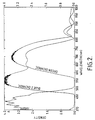
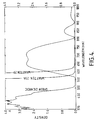
- Figs 1-4 are absorption curves of density vs. wavelength for various filters described in the specification.
- a simple technique for scanning is to scan the photographically processed element point-by-point along a series of laterally offset parallel scan paths.
- the intensity of light reflected from or passing through the photographic element at a scanning point is noted by a sensor which converts radiation received into an electrical signal.
- the electrical signal is passed through an analogue to digital converter and sent to memory in a digital computer together with locant information required for pixel location within the image.
- Signal comparisons and mathematical operations to resolve scan records that represent combinations of two or three different images can be undertaken by routine procedures once the information obtained by scanning has been placed in the computer.
- the preferred type of filter is an interference or dichroic filter.
- Such filters are preferred to absorption filters for blue and green filtration especially because they have a lower optical density in the pass band, and this is desirable because fluorescence images are of inherently lower intensity than diffuse reflection or transmission images read with a similar light source. Greater light availability allows faster or more accurate scanning. They also have a particularly sharp absorbance or transmittance edge, making the matching of filter combinations critical, and it has been found that for good results it is important that the absorbance edges of the illuminating and reading filters bear the mutual exclusion relationship described above.
- the absorption edges cross at an optical density of at least 0.5 above the mean minimum densities, preferably at least 1.0 and particularly between 1.0 and 2.0 above the mean minimum densities.
- an infra-red excluding absorption or interference filter and optionally an ultraviolet-excluding filter, are added to the illuminating interference filter, or to the reading filter, or both.
- the wavelength region of concern is 450-550 nm (blue/green).
- the long wavelength absorption edge of the illuminating filter and the short wavelength absorption edge of the reading filter cross at a very low density.
- the two curves cross at a density of about 1.5 thus falling within the scope of the present invention.
- Fig 3 illustrates the absorption of a BG39 filter made by Schott Glasswerke which absorbs in the high red and infrared regions while Fig 4 illustrates two red filters KODAKTM WRATTENTM 23a and 29 together with a green dichroic filter.
- the intersection of the long wavelength edge of the green filter and the absorption edge of the WRATTENTM 23a filter is at a density of about 0.2, whereas the corresponding intersection with the WRATTENTM 29 filter is at a density of about 2.6.
- a method for reading a colour record or records in a photographic material having silver images of substantially the same hue but representing exposures in at least three regions of the visible spectrum and at least one fluorescent or luminescent layer located between two of said image layers comprising scanning the exposed and processed photographic material at least three times to recover colour information, at least one such scan measuring reflection density by employing an exciting illumination source for said fluorescent or luminescent layer and a detector element for the emission, in which said exciting illumination is filtered through an interference or dichroic filter, and said fluorescent or luminescent emission is filtered through a reading filter before arriving at the detector element, the two filters being such that light passed by the illuminating filter is excluded by the reading filter, the mutual exclusion being defined by the requirement that, when graphical plots of optical density versus wavelength for the two filters are superimposed on the same scale, in the wavelength region concerned, the long wavelength absorption edge of the illuminating filter and the short wavelength absorption edge of the reading filter cross at an optical density or absorbance of at least 0.20 above the mean
- a preferred sensitive photographic material to use in the present scanner comprises superimposed image-forming units sensitive to red, green and blue light carried on a support. These units contain silver halide emulsions, often of different photographic speeds, sensitive to the appropriate part of the visible spectrum. No dye-forming colour couplers are present.
- the material is a film coated on transparent film base, in order, with red (R), green (G) and blue (B) sensitive emulsion layer units. Between the blue and green units is a fluorescent layer emitting in the green while between the green and red units is a fluorescent layer emitting in the red.
- the multicolour photographic elements and their photographic processing apart from the specific required features described above, can take any convenient conventional form.
- a summary of conventional photographic element features as well as their exposure and processing is contained in Research Disclosure , Vol. 308, December 1989, Item 308119, and a summary of tabular grain emulsion and photographic element features and their processing is contained in Research Disclosure , Vol. 225, December 1983, Item 22534, the disclosures of which are here incorporated by reference.
- One method of generating the required three colour records comprises transmission scanning the entire film to obtain the total R, G and B densities, exciting the green fluorescent layer and reflection scanning through a green filter to obtain the B density, and exciting the red fluorescent layer and reflection scanning through a red filter to obtain the B & G densities. From these three measurements the R, G and B densities may be derived arithmetically.
- a variety of scanner designs may be used, but particularly convenient are scanners employing a linear or area photodiode array as the detector element.
- Different types of light source may be used, including those providing a continuous spectrum, eg a tungsten, tungsten-halogen lamp or a xenon flash lamp or those providing spectral lines, eg a mercury lamp or those providing coherent radiation, eg a laser.
- the filter may be used to restrict the wavelengths of the continuous or spectral line emission. Use of a laser as the exciting radiation would probably not require a filter.
- a colour recording film having green and red fluorescent interlayers was prepared by coating the following layers in order on cellulose triacetate film base. The layers are described in terms of coated laydown of each component as grams per square metre (g/m2). All emulsions were sulphur-gold sensitised and spectrally sensitised to the appropriate part of the spectrum. The fluorescent dyes were conventionally dispersed in the presence of the coupler solvents tricresyl phosphate and diethyl lauramide for the red and green emitting dyes respectively.
- the silver halide emulsions used were of the tabular grain type except where otherwise stated, and were silver bromoiodide having between 1 and 6 mole % iodide.
- Layer 1 antihalation underlayer Gelatin 1.0 g/m2 Antihalation dye (as a dispersion of solid dye. The dye was a neutral absorber dye which dissolved out of the coating when treated with alkaline processing solution).
- 0.08 Layer 2 red-sensitive layer Gelatin 1.7 Fast red-sensitive emulsion, (grain diameter 3.0 ⁇ m, thickness 0.12 ⁇ m) 0.60 Mid-speed red sensitised emulsion, (diameter 1.5 ⁇ m, thickness 0.11 ⁇ m) 0.23 Slow red-sensitive emulsion, (diameter 0.7 ⁇ m, thickness 0.11 ⁇ m) 0.40 Slow red-sensitive emulsion, (diameter 0.5 ⁇ m, thickness 0.08 ⁇ m) 0.40
- Layer 3 interlayer Gelatin, 2.8 Red-emitting fluorescent dye RF (RF was LumogenTM F Red 300, supplied by BASF AG, and was a red coloured fluorescent dye with peak emission at 610 nm.
- Layer 4 green-sensitive layer Gelatin 2.0 Fast green-sensitive emulsion, (diameter 2.3 ⁇ m, thickness 0.12 ⁇ m) 0.80 Mid green-sensitive emulsion, (dia.1.5 ⁇ m, thickness 0.11 ⁇ m) 0.25 Slow green-sensitive emulsion, (diameter 0.7 ⁇ m, thickness 0.11 ⁇ m) 0.40 Slow green-sensitive emulsion (diameter 0.5 ⁇ m, thickness 0.08 ⁇ m) 0.40
- Layer 5 interlayer Gelatin 2.8 Green-emitting fluorescent dye GF, (GF was Elbasol Fluorescent Brilliant Yellow R, supplied by Holliday Dyes and Chemicals Ltd, and was a yellow coloured fluorescent dye with peak emission at 501 nm.
- emulsion-containing layer 4-hydroxy-6-methyl-1,3,3a,7-tetraazindene, sodium salt, at 1.5 g per mole of silver.
- Surfactants used to aid the coating operation are not listed in these examples.
- Lumogen F Red 300 is described by the manufacturer as a perylene class fluorescent dye, and Elbasol Brilliant Yellow R is described by its manufacturer as a naphthalimide class fluorescent dye.
- a sample of the film was sensitometrically exposed to blue light by passing light from a tungsten lamp through a Wratten 98 filter and through a graduated density step wedge.
- Another sample was sensitometrically exposed to white light by passing light from a tungsten lamp through a Daylight 5 filter and through a graduated density step wedge.
- the film samples were developed for 3.5 minutes at 25°C in the following black-and-white developer solution: Sodium sulphite (anhydrous) 80.0g/l Tris(hydroxymethyl)aminomethane 10.0g/l L-Ascorbic acid 8.0g/l 4-hydroxymethyl-4-methyl-1-phenyl-3-pH adjusted to 8.2 with sulphuric acid 0.25 g/l
- the film was then fixed in an aqueous solution of ammonium thiosulphate which also contained 25 g/l of sodium sulphite.
- the densities of the image steps on the test sample of the film were scanned by imaging an area of the film approximately 24 x 36 mm onto the focal plane of a KodakTM DCS100 digital camera.
- the camera was fitted with a 100mm NikkorTM macro lens, and an appropriate reading filter was placed in front of the lens and normal to the lens axis. This process was repeated on different areas of the film until all the density steps of the film had been scanned.
- the film was illuminated by means of a photographic xenon flash unit placed on the same side of the film as the camera, so that the coated layers were on the same side of the film support as the incident light and the scanner lens.
- An appropriate interference filter was placed over the aperture of the flash unit.
- the position of the flash units, and the lens aperture and sensitivity settings of the camera, were adjusted so that the range of light intensities sampled from the film fell within the sensitivity range of the camera.
- the image data from the camera were loaded into PhotostylerTM software installed on a Compaq Deskpro 486 personal computer.
- the average light intensity measured for each exposure step on the film was calculated and converted to an equivalent optical density (relative to the unexposed areas of the film which were arbitrarily defined to have a density of zero) by means of a previously determined intensity/density calibration curve, determined by relating the camera intensity values to separately determined transmission density values of a photographic step wedge.
- Densities were measured for two sets of colour records: case A, in which the film had received a blue separation exposure, and where the green-emitting fluorescent layer was excited with blue light and the intensity of the emitted green light was measured to give a measure of the silver density in the blue sensitive layer, and case B, in which the film had received a white light exposure and where the red-emitting fluorescent layer was excited with green light, and the intensity of the emitted red light was measured to give a measure of the combined silver densities in the blue and green sensitive layers.
- two different blue interference (dichroic) filters were used on the illuminating xenon flash source, one, Blue1, supplied by L.O.T. Oriel Ltd. and having its longer wavelength absorption edge at about 500nm, and the other, Blue2, supplied by Balzers High Vacuum Ltd. and having its corresponding absorption edge at about 460nm.
- Blue1 supplied by L.O.T. Oriel Ltd. and having its longer wavelength absorption edge at about 500nm
- Blue2 supplied by Balzers High Vacuum Ltd. and having its corresponding absorption edge at about 460nm.
- Each was used in combination with a BG39 glass absorption filter (from Schott Glaswerke) to exclude infrared and long wavelength red light.
- a green dichroic filter supplied by L.O.T.Oriel Ltd., was placed over the camera lens.
- the absorbance spectrum of dichroic filter Blue1 with the spectrum of the green dichroic filter superimposed is shown in Figure 1, and the corresponding spectra for dichroic filter Blue2 and the green dichroic reading filter are shown in Figure 2. It will be seen that the absorption edge crossovers occur at density values of 0.1 and 1.5 respectively.
- the absorbance spectrum of the BG39 filter is shown in Figure 3.
- Table 1 are listed the relative log exposure given to each step on the film sample, and the corresponding image densities in the blue-sensitive layer as measured by the camera using the two filter conditions. It will be seen that the filter combination according to the Invention, Blue 2/Green Dichroic, gave substantially higher density values than the comparative filter combination, Blue 1/Green Dichroic, to give improved scanner discrimination over the density range of the film sample.
- a green interference (dichroic) filter supplied by Oriel
- a BG39 glass filter plus an ultraviolet light-excluding Wratten 1B filter were used in combination on the illuminating xenon flash source.
- Two different reading filters were used in front of the scanner lens, a Wratten 23A absorption filter, and a Wratten 29 absorption filter.
- the preferred embodiment of the invention the combination of a Wratten 29 and the green dichroic filters, maintained better density discrimination at high densities than the Wratten 23A /green dichroic combination.
Landscapes
- Physics & Mathematics (AREA)
- General Physics & Mathematics (AREA)
- Engineering & Computer Science (AREA)
- Multimedia (AREA)
- Signal Processing (AREA)
- Facsimile Scanning Arrangements (AREA)
- Silver Salt Photography Or Processing Solution Therefor (AREA)
Applications Claiming Priority (4)
| Application Number | Priority Date | Filing Date | Title |
|---|---|---|---|
| GB9418699A GB9418699D0 (en) | 1994-09-16 | 1994-09-16 | Method of producing colour information from records of substantially the same hue |
| GB9418699 | 1994-09-16 | ||
| GB9507103 | 1995-04-06 | ||
| GBGB9507103.1A GB9507103D0 (en) | 1995-04-06 | 1995-04-06 | Method of producing colour information from records of substantially the same hue |
Publications (3)
| Publication Number | Publication Date |
|---|---|
| EP0702483A2 true EP0702483A2 (de) | 1996-03-20 |
| EP0702483A3 EP0702483A3 (de) | 1997-01-22 |
| EP0702483B1 EP0702483B1 (de) | 2000-03-01 |
Family
ID=26305637
Family Applications (1)
| Application Number | Title | Priority Date | Filing Date |
|---|---|---|---|
| EP19950202482 Expired - Lifetime EP0702483B1 (de) | 1994-09-16 | 1995-09-13 | Verfahren zur Erzeugung von Farbinformationen aus Aufzeichnungen vom im wesentlichen gleichen Farbton |
Country Status (3)
| Country | Link |
|---|---|
| EP (1) | EP0702483B1 (de) |
| JP (1) | JPH08228259A (de) |
| DE (1) | DE69515238T2 (de) |
Cited By (6)
| Publication number | Priority date | Publication date | Assignee | Title |
|---|---|---|---|---|
| EP0800306A2 (de) * | 1996-04-02 | 1997-10-08 | Eastman Kodak Company | Beleuchtung für Abtaster |
| EP0901042A1 (de) * | 1997-09-05 | 1999-03-10 | Eastman Kodak Company | Eine Verbesserung von Farbnegativfilmen, geeignet zur digitalen Abtastung |
| US6509126B1 (en) | 2001-12-28 | 2003-01-21 | Eastman Kodak Company | Photothermographic element comprising a fluorescent dye and methods of image formation |
| US6521394B1 (en) | 2001-12-28 | 2003-02-18 | Eastman Kodak Company | Fluorescent photothermographic imaging element comprising coupling agent |
| EP1462826A1 (de) * | 2003-03-28 | 2004-09-29 | Agfa-Gevaert AG | Vorrichtung zum Erfassen von in einer Phosphorschicht enthaltenen Bildinformationen |
| EP1469326A1 (de) * | 2003-03-28 | 2004-10-20 | Agfa-Gevaert AG | Vorrichtung zum Erfassen von in einer Phosphorschicht enthaltenen Bildinformationen |
Families Citing this family (1)
| Publication number | Priority date | Publication date | Assignee | Title |
|---|---|---|---|---|
| JP2003309338A (ja) * | 2002-04-15 | 2003-10-31 | Fujitsu Ltd | 基板、接続構造及び電子装置 |
Citations (1)
| Publication number | Priority date | Publication date | Assignee | Title |
|---|---|---|---|---|
| US4543308A (en) | 1982-05-04 | 1985-09-24 | Agfa-Gevaert Aktiengesellschaft | Photographic recording process |
Family Cites Families (3)
| Publication number | Priority date | Publication date | Assignee | Title |
|---|---|---|---|---|
| JPS60146567A (ja) * | 1984-01-10 | 1985-08-02 | Sharp Corp | カラ−画像読取装置 |
| CA1229181A (en) * | 1984-03-09 | 1987-11-10 | Shigeru Saotome | Radiation image read-out apparatus |
| GB9302819D0 (en) * | 1993-02-12 | 1993-03-31 | Kodak Ltd | Photographic elements for producing blue,green and red exposure records of the same hue and methods,for the retrieval and differentiation of the exposure reco |
-
1995
- 1995-09-13 EP EP19950202482 patent/EP0702483B1/de not_active Expired - Lifetime
- 1995-09-13 DE DE1995615238 patent/DE69515238T2/de not_active Expired - Fee Related
- 1995-09-18 JP JP7238495A patent/JPH08228259A/ja active Pending
Patent Citations (1)
| Publication number | Priority date | Publication date | Assignee | Title |
|---|---|---|---|---|
| US4543308A (en) | 1982-05-04 | 1985-09-24 | Agfa-Gevaert Aktiengesellschaft | Photographic recording process |
Non-Patent Citations (2)
| Title |
|---|
| RESEARCH DISCLOSURE, vol. 225, no. 034, December 1983 (1983-12-01) |
| RESEARCH DISCLOSURE, vol. 308, no. 119, December 1989 (1989-12-01) |
Cited By (10)
| Publication number | Priority date | Publication date | Assignee | Title |
|---|---|---|---|---|
| EP0800306A2 (de) * | 1996-04-02 | 1997-10-08 | Eastman Kodak Company | Beleuchtung für Abtaster |
| EP0800306A3 (de) * | 1996-04-02 | 1998-09-23 | Eastman Kodak Company | Beleuchtung für Abtaster |
| US5969824A (en) * | 1996-04-02 | 1999-10-19 | Eastman Kodak Company | Illumination for scanners |
| EP0901042A1 (de) * | 1997-09-05 | 1999-03-10 | Eastman Kodak Company | Eine Verbesserung von Farbnegativfilmen, geeignet zur digitalen Abtastung |
| US6509126B1 (en) | 2001-12-28 | 2003-01-21 | Eastman Kodak Company | Photothermographic element comprising a fluorescent dye and methods of image formation |
| US6521394B1 (en) | 2001-12-28 | 2003-02-18 | Eastman Kodak Company | Fluorescent photothermographic imaging element comprising coupling agent |
| EP1462826A1 (de) * | 2003-03-28 | 2004-09-29 | Agfa-Gevaert AG | Vorrichtung zum Erfassen von in einer Phosphorschicht enthaltenen Bildinformationen |
| EP1469326A1 (de) * | 2003-03-28 | 2004-10-20 | Agfa-Gevaert AG | Vorrichtung zum Erfassen von in einer Phosphorschicht enthaltenen Bildinformationen |
| US7071484B2 (en) | 2003-03-28 | 2006-07-04 | Agfa-Gevaert Healthcare Gmbh | Device for acquiring information contained in a phosphor layer |
| US7176476B2 (en) | 2003-03-28 | 2007-02-13 | Agfa- Gevaert Healthcare Gmbh | Device for acquiring information contained in a phosphor layer |
Also Published As
| Publication number | Publication date |
|---|---|
| EP0702483B1 (de) | 2000-03-01 |
| DE69515238D1 (de) | 2000-04-06 |
| DE69515238T2 (de) | 2000-09-28 |
| JPH08228259A (ja) | 1996-09-03 |
| EP0702483A3 (de) | 1997-01-22 |
Similar Documents
| Publication | Publication Date | Title |
|---|---|---|
| US5391443A (en) | Process for the extraction of spectral image records from dye image forming photographic elements | |
| US4416961A (en) | Color imaging devices and color filter arrays using photo-bleachable dyes | |
| US4345011A (en) | Color imaging devices and color filter arrays using photo-bleachable dyes | |
| JPH06266066A (ja) | 個別の像様露光記録を得る方法及びそのための写真要素 | |
| JP3227028B2 (ja) | 優れた写真記録を生成するための要素及び方法 | |
| US5350650A (en) | Methods for the retrieval of blue, green and red exposure records of the same hue from a photographic element containing emissive interlayers | |
| JPH11331508A (ja) | スキャナ及びそのスペクトル較正方法並びにスキャナを用いたイメ―ジ走査方法 | |
| JP2003519410A (ja) | 可視光を使用してデジタルフィルムを現像するための改良されたシステムおよび方法 | |
| US6555278B1 (en) | Color filter array film | |
| US20050141046A1 (en) | Image reading apparatus, image recording medium and image forming apparatus | |
| US4416539A (en) | Method of locating abnormal originals | |
| EP0702483B1 (de) | Verfahren zur Erzeugung von Farbinformationen aus Aufzeichnungen vom im wesentlichen gleichen Farbton | |
| EP0450033B1 (de) | Farbabbildungsverfahren | |
| US5334469A (en) | Photographic processes for producing spectral image records retrievable by scanning | |
| EP0526931B1 (de) | Verfahren zur Farbauszugsbildung aus farbstoffbildformenden photographischen Elementen | |
| US4247799A (en) | Color imaging devices and color filter arrays using photo-bleachable dyes | |
| US6475711B1 (en) | Photographic element and digital film processing method using same | |
| US6667138B2 (en) | Image forming method using silver halide color photographic light-sensitive material and image forming apparatus therefore | |
| GB2294777A (en) | Photographic colour material | |
| JP2001036811A (ja) | 画像読取装置及び方法 | |
| US5969824A (en) | Illumination for scanners | |
| US20010048818A1 (en) | Scanning apparatus and digital film processing method | |
| EP1205792B1 (de) | Vorrichtung und Verfahren zum Aufzeichnen bzw. Wiedergeben von farbigen Bildinformation mittels eines Schwarz-Weiss Films | |
| SU1068876A1 (ru) | Способ цветовой дискриминации элементов изображени негатива | |
| US5909292A (en) | Scanning of images |
Legal Events
| Date | Code | Title | Description |
|---|---|---|---|
| PUAI | Public reference made under article 153(3) epc to a published international application that has entered the european phase |
Free format text: ORIGINAL CODE: 0009012 |
|
| AK | Designated contracting states |
Kind code of ref document: A2 Designated state(s): CH DE FR GB IT LI NL |
|
| PUAL | Search report despatched |
Free format text: ORIGINAL CODE: 0009013 |
|
| AK | Designated contracting states |
Kind code of ref document: A3 Designated state(s): CH DE FR GB IT LI NL |
|
| 17P | Request for examination filed |
Effective date: 19970624 |
|
| GRAG | Despatch of communication of intention to grant |
Free format text: ORIGINAL CODE: EPIDOS AGRA |
|
| 17Q | First examination report despatched |
Effective date: 19990610 |
|
| GRAG | Despatch of communication of intention to grant |
Free format text: ORIGINAL CODE: EPIDOS AGRA |
|
| GRAH | Despatch of communication of intention to grant a patent |
Free format text: ORIGINAL CODE: EPIDOS IGRA |
|
| GRAH | Despatch of communication of intention to grant a patent |
Free format text: ORIGINAL CODE: EPIDOS IGRA |
|
| GRAA | (expected) grant |
Free format text: ORIGINAL CODE: 0009210 |
|
| ITF | It: translation for a ep patent filed |
Owner name: BARZANO' E ZANARDO MILANO S.P.A. |
|
| AK | Designated contracting states |
Kind code of ref document: B1 Designated state(s): CH DE FR GB IT LI NL |
|
| REG | Reference to a national code |
Ref country code: CH Ref legal event code: EP |
|
| REF | Corresponds to: |
Ref document number: 69515238 Country of ref document: DE Date of ref document: 20000406 |
|
| REG | Reference to a national code |
Ref country code: CH Ref legal event code: NV Representative=s name: KIRKER & CIE SA |
|
| ET | Fr: translation filed | ||
| PLBE | No opposition filed within time limit |
Free format text: ORIGINAL CODE: 0009261 |
|
| STAA | Information on the status of an ep patent application or granted ep patent |
Free format text: STATUS: NO OPPOSITION FILED WITHIN TIME LIMIT |
|
| REG | Reference to a national code |
Ref country code: GB Ref legal event code: 732E |
|
| 26N | No opposition filed | ||
| PGFP | Annual fee paid to national office [announced via postgrant information from national office to epo] |
Ref country code: NL Payment date: 20010618 Year of fee payment: 7 |
|
| PGFP | Annual fee paid to national office [announced via postgrant information from national office to epo] |
Ref country code: GB Payment date: 20010807 Year of fee payment: 7 |
|
| PGFP | Annual fee paid to national office [announced via postgrant information from national office to epo] |
Ref country code: FR Payment date: 20010831 Year of fee payment: 7 |
|
| PGFP | Annual fee paid to national office [announced via postgrant information from national office to epo] |
Ref country code: DE Payment date: 20010927 Year of fee payment: 7 Ref country code: CH Payment date: 20010927 Year of fee payment: 7 |
|
| REG | Reference to a national code |
Ref country code: GB Ref legal event code: IF02 |
|
| PG25 | Lapsed in a contracting state [announced via postgrant information from national office to epo] |
Ref country code: GB Free format text: LAPSE BECAUSE OF NON-PAYMENT OF DUE FEES Effective date: 20020913 |
|
| PG25 | Lapsed in a contracting state [announced via postgrant information from national office to epo] |
Ref country code: LI Free format text: LAPSE BECAUSE OF NON-PAYMENT OF DUE FEES Effective date: 20020930 Ref country code: CH Free format text: LAPSE BECAUSE OF NON-PAYMENT OF DUE FEES Effective date: 20020930 |
|
| PG25 | Lapsed in a contracting state [announced via postgrant information from national office to epo] |
Ref country code: NL Free format text: LAPSE BECAUSE OF NON-PAYMENT OF DUE FEES Effective date: 20030401 Ref country code: DE Free format text: LAPSE BECAUSE OF NON-PAYMENT OF DUE FEES Effective date: 20030401 |
|
| GBPC | Gb: european patent ceased through non-payment of renewal fee |
Effective date: 20020913 |
|
| REG | Reference to a national code |
Ref country code: CH Ref legal event code: PL |
|
| PG25 | Lapsed in a contracting state [announced via postgrant information from national office to epo] |
Ref country code: FR Free format text: LAPSE BECAUSE OF NON-PAYMENT OF DUE FEES Effective date: 20030603 |
|
| REG | Reference to a national code |
Ref country code: FR Ref legal event code: ST |
|
| PG25 | Lapsed in a contracting state [announced via postgrant information from national office to epo] |
Ref country code: IT Free format text: LAPSE BECAUSE OF NON-PAYMENT OF DUE FEES;WARNING: LAPSES OF ITALIAN PATENTS WITH EFFECTIVE DATE BEFORE 2007 MAY HAVE OCCURRED AT ANY TIME BEFORE 2007. THE CORRECT EFFECTIVE DATE MAY BE DIFFERENT FROM THE ONE RECORDED. Effective date: 20050913 |