EP0450033B1 - Farbabbildungsverfahren - Google Patents
Farbabbildungsverfahren Download PDFInfo
- Publication number
- EP0450033B1 EP0450033B1 EP90915650A EP90915650A EP0450033B1 EP 0450033 B1 EP0450033 B1 EP 0450033B1 EP 90915650 A EP90915650 A EP 90915650A EP 90915650 A EP90915650 A EP 90915650A EP 0450033 B1 EP0450033 B1 EP 0450033B1
- Authority
- EP
- European Patent Office
- Prior art keywords
- image
- exposure
- magenta
- yellow
- cyan
- Prior art date
- Legal status (The legal status is an assumption and is not a legal conclusion. Google has not performed a legal analysis and makes no representation as to the accuracy of the status listed.)
- Expired - Lifetime
Links
- 238000000034 method Methods 0.000 title claims abstract description 52
- 230000008569 process Effects 0.000 title claims abstract description 47
- 238000003384 imaging method Methods 0.000 title description 8
- 239000000839 emulsion Substances 0.000 claims abstract description 63
- -1 silver halide Chemical class 0.000 claims abstract description 47
- 229910052709 silver Inorganic materials 0.000 claims abstract description 45
- 239000004332 silver Substances 0.000 claims abstract description 45
- 230000003595 spectral effect Effects 0.000 claims abstract description 21
- 230000035945 sensitivity Effects 0.000 claims abstract description 17
- 230000005855 radiation Effects 0.000 claims abstract description 11
- 238000001454 recorded image Methods 0.000 claims abstract 3
- 239000000975 dye Substances 0.000 claims description 19
- 238000009826 distribution Methods 0.000 claims description 13
- 238000012937 correction Methods 0.000 claims description 12
- 230000000873 masking effect Effects 0.000 claims description 9
- 238000012986 modification Methods 0.000 claims description 7
- 230000004048 modification Effects 0.000 claims description 7
- 238000000926 separation method Methods 0.000 claims description 5
- 239000007787 solid Substances 0.000 claims description 5
- 150000001875 compounds Chemical class 0.000 claims description 4
- 238000001228 spectrum Methods 0.000 claims description 4
- 238000002835 absorbance Methods 0.000 claims description 3
- 239000010410 layer Substances 0.000 description 13
- 238000011160 research Methods 0.000 description 9
- 230000006870 function Effects 0.000 description 8
- 239000000463 material Substances 0.000 description 8
- 238000012545 processing Methods 0.000 description 8
- 238000013507 mapping Methods 0.000 description 6
- QYSXJUFSXHHAJI-YRZJJWOYSA-N vitamin D3 Chemical compound C1(/[C@@H]2CC[C@@H]([C@]2(CCC1)C)[C@H](C)CCCC(C)C)=C\C=C1\C[C@@H](O)CCC1=C QYSXJUFSXHHAJI-YRZJJWOYSA-N 0.000 description 6
- 238000010586 diagram Methods 0.000 description 5
- 241001637516 Polygonia c-album Species 0.000 description 4
- 238000010521 absorption reaction Methods 0.000 description 4
- 206010070834 Sensitisation Diseases 0.000 description 3
- 239000000654 additive Substances 0.000 description 3
- 238000000149 argon plasma sintering Methods 0.000 description 3
- 239000011159 matrix material Substances 0.000 description 3
- 230000003287 optical effect Effects 0.000 description 3
- 238000001556 precipitation Methods 0.000 description 3
- 230000008313 sensitization Effects 0.000 description 3
- DGAQECJNVWCQMB-PUAWFVPOSA-M Ilexoside XXIX Chemical compound C[C@@H]1CC[C@@]2(CC[C@@]3(C(=CC[C@H]4[C@]3(CC[C@@H]5[C@@]4(CC[C@@H](C5(C)C)OS(=O)(=O)[O-])C)C)[C@@H]2[C@]1(C)O)C)C(=O)O[C@H]6[C@@H]([C@H]([C@@H]([C@H](O6)CO)O)O)O.[Na+] DGAQECJNVWCQMB-PUAWFVPOSA-M 0.000 description 2
- ZLMJMSJWJFRBEC-UHFFFAOYSA-N Potassium Chemical compound [K] ZLMJMSJWJFRBEC-UHFFFAOYSA-N 0.000 description 2
- 239000007864 aqueous solution Substances 0.000 description 2
- 230000008901 benefit Effects 0.000 description 2
- 238000004061 bleaching Methods 0.000 description 2
- 239000007844 bleaching agent Substances 0.000 description 2
- 239000003086 colorant Substances 0.000 description 2
- 238000011161 development Methods 0.000 description 2
- 238000005516 engineering process Methods 0.000 description 2
- 239000011229 interlayer Substances 0.000 description 2
- 239000011591 potassium Substances 0.000 description 2
- 238000002360 preparation method Methods 0.000 description 2
- 150000003839 salts Chemical class 0.000 description 2
- 238000003860 storage Methods 0.000 description 2
- UMGDCJDMYOKAJW-UHFFFAOYSA-N thiourea Chemical compound NC(N)=S UMGDCJDMYOKAJW-UHFFFAOYSA-N 0.000 description 2
- UOMQUZPKALKDCA-UHFFFAOYSA-K 2-[2-[bis(carboxylatomethyl)amino]ethyl-(carboxymethyl)amino]acetate;iron(3+) Chemical class [Fe+3].OC(=O)CN(CC([O-])=O)CCN(CC([O-])=O)CC([O-])=O UOMQUZPKALKDCA-UHFFFAOYSA-K 0.000 description 1
- JKFYKCYQEWQPTM-UHFFFAOYSA-N 2-azaniumyl-2-(4-fluorophenyl)acetate Chemical compound OC(=O)C(N)C1=CC=C(F)C=C1 JKFYKCYQEWQPTM-UHFFFAOYSA-N 0.000 description 1
- QGZKDVFQNNGYKY-UHFFFAOYSA-O Ammonium Chemical compound [NH4+] QGZKDVFQNNGYKY-UHFFFAOYSA-O 0.000 description 1
- 229920001747 Cellulose diacetate Polymers 0.000 description 1
- 229920002284 Cellulose triacetate Polymers 0.000 description 1
- VTLYFUHAOXGGBS-UHFFFAOYSA-N Fe3+ Chemical compound [Fe+3] VTLYFUHAOXGGBS-UHFFFAOYSA-N 0.000 description 1
- 108010010803 Gelatin Proteins 0.000 description 1
- 229910021578 Iron(III) chloride Inorganic materials 0.000 description 1
- 229910021607 Silver chloride Inorganic materials 0.000 description 1
- 229910021612 Silver iodide Inorganic materials 0.000 description 1
- XSQUKJJJFZCRTK-UHFFFAOYSA-N Urea Natural products NC(N)=O XSQUKJJJFZCRTK-UHFFFAOYSA-N 0.000 description 1
- NNLVGZFZQQXQNW-ADJNRHBOSA-N [(2r,3r,4s,5r,6s)-4,5-diacetyloxy-3-[(2s,3r,4s,5r,6r)-3,4,5-triacetyloxy-6-(acetyloxymethyl)oxan-2-yl]oxy-6-[(2r,3r,4s,5r,6s)-4,5,6-triacetyloxy-2-(acetyloxymethyl)oxan-3-yl]oxyoxan-2-yl]methyl acetate Chemical compound O([C@@H]1O[C@@H]([C@H]([C@H](OC(C)=O)[C@H]1OC(C)=O)O[C@H]1[C@@H]([C@@H](OC(C)=O)[C@H](OC(C)=O)[C@@H](COC(C)=O)O1)OC(C)=O)COC(=O)C)[C@@H]1[C@@H](COC(C)=O)O[C@@H](OC(C)=O)[C@H](OC(C)=O)[C@H]1OC(C)=O NNLVGZFZQQXQNW-ADJNRHBOSA-N 0.000 description 1
- SJOOOZPMQAWAOP-UHFFFAOYSA-N [Ag].BrCl Chemical compound [Ag].BrCl SJOOOZPMQAWAOP-UHFFFAOYSA-N 0.000 description 1
- HOLVRJRSWZOAJU-UHFFFAOYSA-N [Ag].ICl Chemical compound [Ag].ICl HOLVRJRSWZOAJU-UHFFFAOYSA-N 0.000 description 1
- 239000006096 absorbing agent Substances 0.000 description 1
- 238000000862 absorption spectrum Methods 0.000 description 1
- 230000000996 additive effect Effects 0.000 description 1
- 150000001298 alcohols Chemical class 0.000 description 1
- ROOXNKNUYICQNP-UHFFFAOYSA-N ammonium peroxydisulfate Substances [NH4+].[NH4+].[O-]S(=O)(=O)OOS([O-])(=O)=O ROOXNKNUYICQNP-UHFFFAOYSA-N 0.000 description 1
- VAZSKTXWXKYQJF-UHFFFAOYSA-N ammonium persulfate Chemical compound [NH4+].[NH4+].[O-]S(=O)OOS([O-])=O VAZSKTXWXKYQJF-UHFFFAOYSA-N 0.000 description 1
- 229910001870 ammonium persulfate Inorganic materials 0.000 description 1
- XYXNTHIYBIDHGM-UHFFFAOYSA-N ammonium thiosulfate Chemical compound [NH4+].[NH4+].[O-]S([O-])(=O)=S XYXNTHIYBIDHGM-UHFFFAOYSA-N 0.000 description 1
- 230000004888 barrier function Effects 0.000 description 1
- 229920002678 cellulose Polymers 0.000 description 1
- 239000003153 chemical reaction reagent Substances 0.000 description 1
- 239000003795 chemical substances by application Substances 0.000 description 1
- 239000011248 coating agent Substances 0.000 description 1
- 238000000576 coating method Methods 0.000 description 1
- 239000013078 crystal Substances 0.000 description 1
- 238000013479 data entry Methods 0.000 description 1
- GLGSRACCZFMWDT-UHFFFAOYSA-N dilithium;oxido-(oxido(dioxo)chromio)oxy-dioxochromium Chemical compound [Li+].[Li+].[O-][Cr](=O)(=O)O[Cr]([O-])(=O)=O GLGSRACCZFMWDT-UHFFFAOYSA-N 0.000 description 1
- 230000000694 effects Effects 0.000 description 1
- 239000010946 fine silver Substances 0.000 description 1
- 239000008273 gelatin Substances 0.000 description 1
- 229920000159 gelatin Polymers 0.000 description 1
- 235000019322 gelatine Nutrition 0.000 description 1
- 235000011852 gelatine desserts Nutrition 0.000 description 1
- 150000002344 gold compounds Chemical class 0.000 description 1
- 150000004820 halides Chemical class 0.000 description 1
- 238000010348 incorporation Methods 0.000 description 1
- 238000002329 infrared spectrum Methods 0.000 description 1
- 239000003112 inhibitor Substances 0.000 description 1
- 150000002504 iridium compounds Chemical class 0.000 description 1
- RBTARNINKXHZNM-UHFFFAOYSA-K iron trichloride Chemical compound Cl[Fe](Cl)Cl RBTARNINKXHZNM-UHFFFAOYSA-K 0.000 description 1
- 239000000314 lubricant Substances 0.000 description 1
- 238000004519 manufacturing process Methods 0.000 description 1
- 239000006224 matting agent Substances 0.000 description 1
- DZVCFNFOPIZQKX-LTHRDKTGSA-M merocyanine Chemical compound [Na+].O=C1N(CCCC)C(=O)N(CCCC)C(=O)C1=C\C=C\C=C/1N(CCCS([O-])(=O)=O)C2=CC=CC=C2O\1 DZVCFNFOPIZQKX-LTHRDKTGSA-M 0.000 description 1
- 150000002736 metal compounds Chemical class 0.000 description 1
- 239000000203 mixture Substances 0.000 description 1
- 239000007800 oxidant agent Substances 0.000 description 1
- JRKICGRDRMAZLK-UHFFFAOYSA-L persulfate group Chemical group S(=O)(=O)([O-])OOS(=O)(=O)[O-] JRKICGRDRMAZLK-UHFFFAOYSA-L 0.000 description 1
- 239000004014 plasticizer Substances 0.000 description 1
- 229920000728 polyester Polymers 0.000 description 1
- 229920000139 polyethylene terephthalate Polymers 0.000 description 1
- 239000004848 polyfunctional curative Substances 0.000 description 1
- 229920000642 polymer Polymers 0.000 description 1
- 229910052700 potassium Inorganic materials 0.000 description 1
- 159000000001 potassium salts Chemical class 0.000 description 1
- 229910052939 potassium sulfate Inorganic materials 0.000 description 1
- ZNNZYHKDIALBAK-UHFFFAOYSA-M potassium thiocyanate Chemical compound [K+].[S-]C#N ZNNZYHKDIALBAK-UHFFFAOYSA-M 0.000 description 1
- 229940116357 potassium thiocyanate Drugs 0.000 description 1
- 230000004044 response Effects 0.000 description 1
- 229920006395 saturated elastomer Polymers 0.000 description 1
- 229940065287 selenium compound Drugs 0.000 description 1
- 150000003343 selenium compounds Chemical class 0.000 description 1
- 230000001235 sensitizing effect Effects 0.000 description 1
- ADZWSOLPGZMUMY-UHFFFAOYSA-M silver bromide Chemical compound [Ag]Br ADZWSOLPGZMUMY-UHFFFAOYSA-M 0.000 description 1
- ZUNKMNLKJXRCDM-UHFFFAOYSA-N silver bromoiodide Chemical compound [Ag].IBr ZUNKMNLKJXRCDM-UHFFFAOYSA-N 0.000 description 1
- 229940045105 silver iodide Drugs 0.000 description 1
- HKZLPVFGJNLROG-UHFFFAOYSA-M silver monochloride Chemical compound [Cl-].[Ag+] HKZLPVFGJNLROG-UHFFFAOYSA-M 0.000 description 1
- 239000002356 single layer Substances 0.000 description 1
- 229910052708 sodium Inorganic materials 0.000 description 1
- 239000011734 sodium Substances 0.000 description 1
- CHQMHPLRPQMAMX-UHFFFAOYSA-L sodium persulfate Substances [Na+].[Na+].[O-]S(=O)(=O)OOS([O-])(=O)=O CHQMHPLRPQMAMX-UHFFFAOYSA-L 0.000 description 1
- VGTPCRGMBIAPIM-UHFFFAOYSA-M sodium thiocyanate Chemical compound [Na+].[S-]C#N VGTPCRGMBIAPIM-UHFFFAOYSA-M 0.000 description 1
- AKHNMLFCWUSKQB-UHFFFAOYSA-L sodium thiosulfate Chemical compound [Na+].[Na+].[O-]S([O-])(=O)=S AKHNMLFCWUSKQB-UHFFFAOYSA-L 0.000 description 1
- 235000019345 sodium thiosulphate Nutrition 0.000 description 1
- 239000000243 solution Substances 0.000 description 1
- 239000003381 stabilizer Substances 0.000 description 1
- 125000005504 styryl group Chemical group 0.000 description 1
- 239000000126 substance Substances 0.000 description 1
- 150000003464 sulfur compounds Chemical class 0.000 description 1
- 239000004094 surface-active agent Substances 0.000 description 1
- 238000012360 testing method Methods 0.000 description 1
- ANRHNWWPFJCPAZ-UHFFFAOYSA-M thionine Chemical compound [Cl-].C1=CC(N)=CC2=[S+]C3=CC(N)=CC=C3N=C21 ANRHNWWPFJCPAZ-UHFFFAOYSA-M 0.000 description 1
- 238000001429 visible spectrum Methods 0.000 description 1
- XLYOFNOQVPJJNP-UHFFFAOYSA-N water Substances O XLYOFNOQVPJJNP-UHFFFAOYSA-N 0.000 description 1
- 239000008207 working material Substances 0.000 description 1
Images


Classifications
-
- G—PHYSICS
- G03—PHOTOGRAPHY; CINEMATOGRAPHY; ANALOGOUS TECHNIQUES USING WAVES OTHER THAN OPTICAL WAVES; ELECTROGRAPHY; HOLOGRAPHY
- G03C—PHOTOSENSITIVE MATERIALS FOR PHOTOGRAPHIC PURPOSES; PHOTOGRAPHIC PROCESSES, e.g. CINE, X-RAY, COLOUR, STEREO-PHOTOGRAPHIC PROCESSES; AUXILIARY PROCESSES IN PHOTOGRAPHY
- G03C7/00—Multicolour photographic processes or agents therefor; Regeneration of such processing agents; Photosensitive materials for multicolour processes
- G03C7/18—Processes for the correction of the colour image in subtractive colour photography
-
- G—PHYSICS
- G03—PHOTOGRAPHY; CINEMATOGRAPHY; ANALOGOUS TECHNIQUES USING WAVES OTHER THAN OPTICAL WAVES; ELECTROGRAPHY; HOLOGRAPHY
- G03C—PHOTOSENSITIVE MATERIALS FOR PHOTOGRAPHIC PURPOSES; PHOTOGRAPHIC PROCESSES, e.g. CINE, X-RAY, COLOUR, STEREO-PHOTOGRAPHIC PROCESSES; AUXILIARY PROCESSES IN PHOTOGRAPHY
- G03C5/00—Photographic processes or agents therefor; Regeneration of such processing agents
- G03C5/16—X-ray, infrared, or ultraviolet ray processes
- G03C5/164—Infrared processes
-
- G—PHYSICS
- G03—PHOTOGRAPHY; CINEMATOGRAPHY; ANALOGOUS TECHNIQUES USING WAVES OTHER THAN OPTICAL WAVES; ELECTROGRAPHY; HOLOGRAPHY
- G03C—PHOTOSENSITIVE MATERIALS FOR PHOTOGRAPHIC PURPOSES; PHOTOGRAPHIC PROCESSES, e.g. CINE, X-RAY, COLOUR, STEREO-PHOTOGRAPHIC PROCESSES; AUXILIARY PROCESSES IN PHOTOGRAPHY
- G03C7/00—Multicolour photographic processes or agents therefor; Regeneration of such processing agents; Photosensitive materials for multicolour processes
- G03C7/30—Colour processes using colour-coupling substances; Materials therefor; Preparing or processing such materials
- G03C7/3041—Materials with specific sensitometric characteristics, e.g. gamma, density
Definitions
- This invention relates to photography and specifically to a process for recording a continuous tone color image.
- continuous tone images are traditionally formed by exposing a photographic element to an image and developing the element to form a corresponding image therein.
- the element's image will usually be of a single record.
- the element's corresponding image is usually made up of three records: a yellow record, a magenta record, and a cyan record, corresponding to the blue, green, and red portions of the original image.
- Photographic elements are generally of two types: negative or reversal. For either of these types, it is often desirable to produce a negative or positive copy. This copying is done by exposing a second photographic element with light that is transmitted through a previously exposed and processed first element made on transparent base or with light that is reflected from a previously exposed and processed first element made on a reflective base. The second element is then developed to yield the copy.
- a photographic element such as the second photographic element described above
- the ability of a photographic element, such as the second photographic element described above, to reproduce the contrast, i.e., the range of image densities, of an image is usually determined by the slope of the straight-line portion of the characteristic curve, i.e., the D-Log E curve (a plot of image density versus log exposure). This slope is referred to as gamma and is a measure of the contrast characteristics of a photographic element.
- "Contrast" will be used herein to refer to the qualitative appearance of the image, as opposed to other usages in the art where contrast has sometimes been used interchangeably for gamma.
- Another way to quantify the contrast of an image, independent of gamma is by the range of densities found in the image. A lower contrast image will typically have a lower image density range than a higher contrast image.
- a photographic element having a gamma with an absolute value of approximately unity is used.
- a photographic element having a gamma with an absolute value of less than 1 is used.
- a photographic element having a gamma with an absolute value of greater than 1 is used to produce a photographic copy having greater contrast than the original.
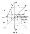
- FIGS. 1-3 are four-quadrant objective tone scale reproduction diagrams, similar to those shown in B. Carroll, G. Higgins, and T. James, Introduction to Photographic Theory, chapt. 5, Wiley Publ., New York, 1980.
- FIG. 1 represents the matched-contrast scenario
- FIG. 2 represents the reduced-contrast scenario
- FIG. 3 represents the increased-contrast scenario.
- the image density range of the original is represented on the horizontal axis at the top of Quadrant 1 (Q1).
- the densities represented by this range are the input data for lines 11, 21, and 31 of Figures 1, 2, and 3, respectively.
- Line 11, 21, or 31 is a straight line having a slope of -1, performing the function of mapping the input data representing the densities of the original from Quadrant 1 into Quadrant 2 (Q2) .
- Line 12, 22, or 32 in Quadrant 2 is a line having a slope of 1, representing the mapping of the density input from the original to a log exposure output that is provided to the photographic element onto which the copy is made.
- Curves 13, 23, and 33 in Quadrant 3 (Q3) represents the characteristic D-Log E curve of a negative-working photographic element onto which the copy is made.
- curve 13 has a straight-line slope (i.e., gamma) of 1.
- gamma straight-line slope
- curve 23 has a straight-line slope (i.e., gamma) of less than 1.
- curve 33 has a straight-line slope (i.e., gamma) of greater than 1.
- Line 14, 24, or 34 in Quadrant 4 is a straight line having a slope of 1, which performs the function of mapping the densities of the copy image onto the horizontal axis at the top of Quadrant 1, so that the density range of the copy can be compared with the density range of the original.
- the above-described mapping operations are represented by dotted lines 15, 25, and 35, and dashed lines 16, 26, and 36. These lines map a representative low and a representative high density on the original, through Quadrants 1, 2, 3, and 4 in the direction of the arrows shown on lines 15, 25, 35, 16, 26, and 36, ending up as densities on the copy on the horizontal axis at the bottom of Quadrant 4.
- FIG. 1 the matched contrast scenario represented by FIG.
- the density range of the copy is the same as the density range of the original.
- the density range of the copy is smaller than the density range of the original.
- the density range of the copy is greater than the density range of the original.
- the photographic element onto which the copy is made traditionally must have a gamma with an absolute value of less than or equal to 1.
- the emulsion system used in the element must have a broad exposure latitude.
- curve 100 represents a faster, short-latitude emulsion having larger grain sizes
- curve 110 represents a slower, short-latitude emulsion having smaller grain sizes
- curve 130 represents the additive latitude-broadening effect of the two emulsions.
- Curve 140 represents a single short-latitude emulsion that achieves the desired D-max, but which necessarily has a high gamma that would not produce a copy having a contrast that is the same as or lower than the original.
- An alternate method for achieving the latitude needed to give a desired D-max with a relatively low gamma is to use a highly polydisperse emulsion.
- highly polydisperse emulsions are difficult to chemically and spectrally sensitize in an optimum fashion, since each of the grain size classes within the emulsion is likely to require a different concentration of reagents to achieve this optimum sensitization. Consequently, the speed/fog characteristics of such emulsions are frequently inferior to monodisperse emulsions.
- reproducible precipitation of a highly polydisperse emulsion is often more difficult than reproducible precipitation of monodisperse emulsion.
- the population of larger grains that are present in highly polydisperse emulsions will contribute to additional light scattering, again reducing the sharpness of the image produced in the element.
- a process for recording a positive or negative continuous tone color copy having substantially the same contrast as a continuous tone original image comprising the steps of:
- the present invention provides a photographic copy having the same or lower contrast than the original image.
- the photographic element onto which the copy is made does not require highly polydisperse silver halide emulsions or multiple silver halide emulsions for each region of spectral sensitivity, yet it still offers satisfactory D-max. This is in contrast to prior art processes, where, when it was desired to make copies having the same or lower contrast than the original, achievement of the exposure latitude and D-max required to make a faithful copy required the use of multiple emulsions or highly polydisperse emulsions and their associated disadvantages.
- FIGS. 1, 2, and 3 are objective tone reproduction diagrams representing prior art processes for producing copies having a contrast that is the same, lower, or higher, respectively, than the original image.
- FIG. 4 shows characteristic curves for photographic emulsions, illustrating how broad latitude photographic elements are obtained.
- FIGS. 5 and 6 are objective tone reproduction diagrams representing the operation useful in the practice of the invention for producing a matched or reduced contrast copy onto a high gamma photographic element.
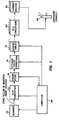
- FIG. 7 is a block diagram representing a preferred process and apparatus useful in the practice of the invention.
- the present invention is directed to recording a continuous tone color copy of an original image, with the copy having a contrast that is the same as or lower than the original.
- the image density range for the copy is the same as or less than the image density range of the original image. This range is defined as the maximum image density (image D-max) minus the minimum image density (image D-min).
- maximum and minimum image densities is meant the maximum and minimum densities providing usable image detail.
- the original image may include a background density which differs from that in the copy or vice versa. Since both the minimum image density and the maximum image density include this background density, the difference between the minimum image density and the maximum image density (the density range) is independent of the magnitude of the background density.
- colored masking couplers are often used to correct for unwanted absorbance of image dyes. These masking couplers generally impart an orange-colored minimum density to the developed negative film. However, the background density imparted by the masking couplers would cancel out when the density range in the image was computed.
- Providing a copy having the same image density range as the original will usually result in the copy having the same contrast as the original. This may not be true, however, in certain limited situations. For example, if the algorithm chosen to modify the image data produced the same minimum and maximum densities in the copy as the original, but produced the midscale densities at higher densities than in the original, the contrast in the lower scale of the copy would be higher than in the original and the contrast in the upper scale of the copy would be lower than in the original.
- the modified image data is used to control the exposure sources so that not only the image density range, but also the distribution of the differences in image density from the mean value of image density, or the distribution of these differences with reversed sign (thus reversing the polarity of the image but leaving it unchanged in absolute value of contrast) for at least one of the yellow, magenta, and cyan image-forming units is substantially the same as the distribution of image density differences from the mean for the corresponding yellow, magenta, and cyan records, respectively, of the original image.
- the modified image data is used to control the exposure sources so that not only the image density range, but also the distribution of the differences in image density from the mean value of image density or the distribution of these differences with reversed sign (thus reversing the polarity of the image but leaving it unchanged in absolute value of contrast) for at least one of the yellow, magenta, and cyan image-forming units is some specified fraction of the distribution of image density differences from the mean for the corresponding yellow, magenta, and cyan records, respectively, of the original image.
- Photographic elements useful in the practice of this invention comprise a support having thereon a yellow image-forming silver halide emulsion unit, a magenta image-forming silver halide emulsion unit, and a cyan image-forming silver halide emulsion unit.
- Each of these units is made up of one or more silver halide emulsion layers. To take maximum advantage of the invention, it is preferred that each unit has only one layer, but the practice of invention is not limited to such one-layer units.
- the support of the element useful in the practice of the invention can be any of a number of well-known supports for photographic elements. These include polymeric films such as cellulose esters (e.g., cellulose triacetate and diacetate) and polyesters of dibasic aromatic carboxylic acids with divalent alcohols (e.g., poly(ethylene terephthalate)), paper, and polymer-coated paper. Such supports are described in further detail in Research Disclosure , December, 1989, Item 308119 [hereinafter referred to as Research Disclosure I ], Section XVII.
- the silver halide emulsions can contain, for example, silver bromide, silver chloride, silver iodide, silver chlorobromide, silver chloroiodide, silver bromoiodide, or mixtures thereof.
- the emulsions can include any of the known grain configurations, such as coarse, medium, or fine silver halide grains bounded by 100, 111, or 110 crystal planes.
- Silver halide emulsions and their preparation are further described in Research Disclosure I , Section I. Also useful are tabular grain silver halide emulsions, such as those described in Research Disclosure , January, 1983, Item 22534 and U.S. Patent 4,425,426.
- the silver halide emulsions may be sensitized with chemical sensitizers such as sulfur compounds, selenium compounds, gold compounds, iridium compounds, or other group VIII metal compounds, as is known in the art.
- each of the silver halide emulsion units useful in the practice of the invention has a maximum spectral sensitivity at a different wavelength of radiation, such as the red, blue, or green portions of the visible spectrum, or to other wavelength ranges, such as ultraviolet, infrared, X-ray, and the like.
- each unit has a maximum spectral sensitivity in the red to infrared portion of the spectrum, which allows the exposure sources to be solid state light-emitting diodes (LED's) or solid state infrared lasers.
- LED's solid state light-emitting diodes
- the effectiveness of red and infrared-sensitizing dyes can be improved with bis-azine compounds, as described, for example in U.S. Patent 4,199,360.
- Spectral sensitization of silver halide can be accomplished with spectral sensitizing dyes such as cyanine dyes, merocyanine dyes, styryls, or other known spectral sensitizers. Additional information on sensitization of silver halide is described in Research Disclosure I , Sections I-IV.
- Filter dyes may also be used in the element useful in the practice of the invention.
- Typical known uses of filter dyes include as interlayer dyes, trimmer dyes, or antihalation dyes. They can be used to improve image separation by preventing unwanted blue light from reaching the green-sensitive emulsion layer of a multicolor photographic element (the same principle can be applied when each of the silver halide emulsion units is different to a different portion of the infrared spectrum, as described in U.S. Patent 4,619,892), and other uses as indicated by the absorbance spectrum of the particular dye.
- Filter dyes can be used in a separate filter layer or as an intergrain absorber.
- the silver halide emulsion units of the element useful in the practice of the invention are each capable of forming a yellow image, a magenta image, or a cyan image, respectively. These images are formed by dye-forming couplers that react with oxidized color developer to form dye. The color developer is oxidized imagewise by reacting with exposed silver halide in each of the units. Color dye-forming couplers are well-known in the art and are further described in Research Disclosure I , Section VII.
- the element useful in the practice of the invention can also include any of a number of other well-known additives and layers, as described in Research Disclosure I . These include, for example, optical brighteners, antifoggants, image stabilizers, light-scattering materials, gelatin hardeners, coating aids and various surfactants, overcoat layers, interlayers and barrier layers, antistatic layers, plasticizers and lubricants, matting agents, development inhibitor-releasing couplers, bleach accelerator-releasing couplers, and other additives and layers known in the art.
- the process of the invention serves to record onto the silver halide photographic element a latent image that produces a continuous tone copy of the original upon processing.
- Processing can be by any type of known photographic processing, as described in Research Disclosure I , Sections XIX-XXIV.
- a negative image can be developed by color development with a chromogenic developing agent followed by bleaching and fixing.
- a positive image can be developed by first developing with a non-chromogenic developer, then uniformly fogging the element, and then developing with a chromogenic developer. If the material does not contain a color-forming coupler compound, dye images can be produced by incorporating a coupler in the developer solutions.
- Bleaching and fixing can be performed with any of the materials known to be used for that purpose.
- Bleach baths generally comprise an aqueous solution of an oxidizing agent such as water soluble salts and complexes of iron (III) (e.g., potassium ferricyanide, ferric chloride, ammonium of potassium salts of ferric ethylenediaminetetraacetic acid), water-soluble persulfates (e.g., potassium, sodium, or ammonium persulfate), water-soluble dichromates (e.g., potassium, sodium, and lithium dichromate), and the like.
- an oxidizing agent such as water soluble salts and complexes of iron (III) (e.g., potassium ferricyanide, ferric chloride, ammonium of potassium salts of ferric ethylenediaminetetraacetic acid), water-soluble persulfates (e.g., potassium, sodium, or ammonium persulfate), water-soluble dichromates (e.g., potassium
- Fixing baths generally comprise an aqueous solution of compounds that form soluble salts with silver ions, such as sodium thiosulfate, ammonium thiosulfate, potassium thiocyanate, sodium thiocyanate, thiourea, and the like.
- At least one of the image-forming units of the element useful in the practice of the invention has a gamma that would be inconsistent with producing the desired copy having a contrast, or image density range, that is the same as or lower than the original image.
- at least one of the image-forming units has a gamma of greater than 1.5, and preferably greater than 2.0.
- at least one of the image-forming units has a gamma of greater than 1.0, and preferably greater than 1.5.
- Gamma is defined as the slope of the straight-line portion of the characteristic curve of a given imaging unit in the photographic element. In some instances, such as where the straight-line portion is very short, it is contemplated that equivalents of gamma can be used. Such equivalents include contrast index (see Encyclopedia of Practical Photography, vol. 4, pp. 594-597, American Photographic Book Publ. Co., 1978) or the mean gradient of the useful portion of the characteristic curve (see B. Carroll, G. Higgins, & T. James, Introduction to Photographic Theory, pp. 5, 36 (Wiley, New York, 1980). In either case, the mathematical value of gamma may be either positive (for negative working materials) or negative (for reversal materials). As used herein, gamma values are the absolute value numbers, as the invention applies equally as well to positive or negative copies.
- Silver halide emulsions having specified gammas can ,be prepared by techniques known in the art.
- the gamma of a silver halide emulsion depends primarily on the distribution and range of grain sizes in the emulsion, i.e., the "polydispersity" of the emulsion. Emulsions that are more polydisperse tend to have lower gammas whereas emulsions that are more monodisperse tend to have higher gammas.
- Emulsion precipitation techniques yielding varying degrees of polydispersity and varying gammas are known in the art, as described, for example, in Research Disclosure I , Section I, and James, The Theory of the Photographic Process , ch. 3, MacMillan, 1977.
- the image data that is received according to the invention may come from any of a number of well-known sources. This includes signals such as those from a scanner that reads density data from a hard copy original image, such as a photograph or drawing; signals from an electronic camera; or signals from computer-generated graphics or drawings. Although electronic cameras generally provide data representing the red, green and blue luminance values of an original scene, this data must be translated so as to represent the cyan, magenta, and yellow densities necessary to reproduce a hard copy of the scene. In a preferred embodiment, however, the original image is itself a hard copy and the data to be received is generated by a scanner or reader as is known in the art.
- Such devices generally comprise a light sensor and a color light source (e.g., a white light source and a color filter wheel containing red, blue, and green filters).
- a white light source and an array of color sensors could be used.
- Examples of such useful devices include CRT scanners, drum scanners, flat bed scanners, area image scanners, line sensors, flying spot scanners, and others as described in J. Marie, "Image Scanning and Digitization", ch. 10, in Imaging Processes and Materials , pp. 292-322, (J.
- Image data may be received directly from a scanner, but it is preferable in some instances (e.g., where the speed of the scanner is limited) to store the data (e.g., in a frame store) before it is received by the process and apparatus of the invention.
- the present invention can be used to make copies of any original image. It is especially useful, however, in making equivalent-contrast copies of low-contrast originals and reduced contrast copies of high-contrast originals.
- the original is preferably a photographic element having a gamma of between 0.5 and 1.1. Examples of this include duplicate copies that are used in the standard printing sequence for theatrical motion picture film production.
- the original is preferably a photographic element having a gamma of greater than 1.1, and more preferably greater than 1.5.
- Such materials are generally likely to be transparency films or paper print materials from which it is often desirable to have a low contrast copy to use as an internegative image to produce further copy prints using conventional optical means.
- a situation where the present invention can be particularly useful is when the image separation between the units of at least one set of two image-forming units in the element useful in the practice of the invention is less than 1.7 log exposure units.
- Image separation is defined as the difference in speed observed between an imaging unit capable of forming a first desired color and any other imaging unit capable of forming an image of second color when the element is exposed with a wavelength or band of wavelengths at the maximum spectral sensitivity of the imaging layer producing the first color.
- Such elements are likely to require high gamma image-forming units in order to reduce "punch-through", a phenomenon where the exposure source for one of the image-forming units also results in exposure of one or more of the other image-forming units.
- Such high gamma image-forming units would not be capable of providing copies having contrast that is the same as or lower than the original image using prior art processes.
- FIGS. 5-6 are four-quadrant objective tone scale reproduction diagrams, similar to FIGS. 1-3, described above.
- FIG. 5 represents a matched-contrast scenario
- FIG. 6 represents a reduced-contrast scenario.
- FIGS. 5-6 unlike FIGS. 1-3, utilize image data modification to provide matched or reduced contrast copies using a photographic element having a gamma of greater than unity. Such elements, when used in prior art processes, provided copies having greater contrast than the original.
- the image density range for one of the three colors of the original is represented on the horizontal axis at the top of Quadrant 1 (Q1).
- the densities represented by this range are the input data for lines 51 and 61.
- Lines 51 and 61 are straight lines having a slope of +1 or -1, representing the choice of the polarity of the copy. A slope of -1 keeps the polarity of the image data the same while a slope of +1 (as shown in the figures) reverses the polarity of the image data.
- Lines 51 and 61 may also be offset vertically or horizontally to add or subtract a fixed background density for each color.
- the data representing the image densities of the original is mapped through lines 51 and 61 into Quadrant 2 (Q2), where it is input data for curves 52 and 62. Curves 52 and 62 represent the modification of the image data to control contrast.
- curves 53 and 63 represent a negative working photographic element, the element may be either positive or negative working, as both types may be used to achieve, with an appropriate choice of slope for lines 51 and 61, either a same polarity (positive) or reversed polarity (negative) copy.
- the input log exposure values are mapped through curves 53 and 63 to give the densities of the final copy image on the vertical axis between Quadrants 3 and 4.
- Line 54 or 64 in Quadrant 4 is a straight line having a slope of 1, which performs the function of mapping the densities of the copy image onto the horizontal axis at the top of Quadrant 1, so that the density range of the copy can be compared with the density range of the original.
- the above-described mapping operations are represented by lines 55, 56, 65, and 66. These lines map a representative low and a representative high density on the original, through Quadrants 1, 2, 3, and 4 in the direction of the arrows shown on lines 55, 56, 65, and 66, ending up as densities of the copy on the horizontal axis at the bottom of Quadrant 4.
- FIG. 5 it is seen that the density range of the copy is the same as the density range of the original.
- FIG. 7 represents one preferred embodiment of the invention.
- the original image is pixel-wise scanned by scanner 70, which generates image data representing the densities of the cyan, yellow, and magenta records for the original image.
- the densities of the cyan, yellow, and magenta records for the original image are determined by subjecting each scanned pixel of the image to red, blue, and green light, upon which the light sensor generates an electrical signal representing the image data.
- the signal is converted to a digital value by analog to digital converter 72.
- the number of bits utilized for each digital value should provide for a range of digital values sufficient to represent the number of exposure levels needed for the exposure sources to produce an image of acceptable continuous tone quality.
- the digital value provided by analog to digital converter 72 preferably has at least 8 bits (providing for 256 possible digital values), and more preferably has at least 12 bits (providing for 4096 possible digital values) or 14 bits (providing for 16384 possible digital values).
- the image data thus generated is received by look-up tables 78.
- Scanner 70, analog to digital converter 72, frame store 74, and optional color correction 76 need not be part of the process of the invention, or an apparatus, but are included in FIG. 7 for illustrative purposes as to how the data can be generated.
- the data may be provided directly to look-up tables 78 by analog to digital converter 72, temporarily stored in frame store 74.
- the data may also be down-loaded to computer 86 for longer-term storage, such as on a magnetic tape or disk or optical disk, and loaded back into frame store 74 at some later time.
- Computer 86 can also provide control functions for scanner 70, analog to digital converter 72, frame store 74, as well as data entry and control function for optional color correction 76 and look-up tables 78.
- Optional color correction 76 is provided by color matrixing, as is known in the art. Color matrixing is performed with a function as shown below:
- the color correction matrix shown above is a 3 X 3 matrix for first-order correction, which is generally sufficient to provide an average masking correction for the unwanted overlapping absorption of imaging dyes. Larger matrixes, such as a 3 X 10 matrix, may be used if it is desired to provide a better correction that compensates for the variation of unwanted absorption with exposure level.
- this color correction is utilized to provide a masking correction.
- This is useful because the spectral ranges of absorption of the image dyes formed in silver halide photographic elements overlap and therefore, exposure of a given layer creates absorption not only of the desired color but also of other colors, resulting in dark and desaturated images.
- Masking by incorporation of colored couplers is often used in color negative photography to provide additional color density that is chemically removed by an appropriate amount during processing to compensate for the unwanted density of the image dyes, thus providing lighter and more saturated images. The additional density required for this correction can then be compensated for during later printing and copying processes.
- the process of the present invention can advantageously utilize electronic masking to record either intermediate images (having electronically-added minimum density) or final, viewable images (having no added minimum density) on a single multi-purpose silver halide photographic element that is substantially free of any colored masking couplers.
- the image data is modified to control exposure sources so that the image density range for at least one of the records in the copy is substantially the same as the image density range for the corresponding record in the original image.
- This modification is accomplished in FIG. 7 by look-up tables 78.
- the look-up tables embody the image data modification (for tone scale adjustment) function represented by curves 52 and 62 in FIGS. 5 and 6.
- the use of look-up tables in image processing is well-known in the art.
- one of the look-up tables will provide an output digital value, which, when converted to an analog signal by one of the digital to analog converters 80 and then a driving current by one of the current drivers 82, will cause one of the exposure sources 84 to provide sufficient exposure to the photographic element to record an image pixel that will contribute to an image having the desired image density range.
- the look-up tables thus take into account and compensate for any non-linearity in the response of the reader, the exposure source, or the photographic silver halide emulsion units.
- the characteristic curve shapes of the silver halide emulsion units in the photographic element do not have to match each other, as with conventional photographic printing processes.
- the values for the look-up tables are determined by simple calibration procedures involving exposing the photographic element using test signals and observing the image densities thereby produced.
- the digital to analog converters 80 and current drivers 82 are well-known in the art and do not require further explanation here.
- the exposure sources 84 can be any of a number of well-known types. These include, for example, focused light beams, light-emitting diodes, gas lasers, and laser diodes. Lasers are preferred, as their high intensity allows for the use of fine grain silver halide emulsions (e.g., less than 0.20 ⁇ m and preferably less than 0.10 ⁇ m), which leads to reduced granularity and increased image sharpness. Solid state laser diodes (which currently emit only in the infrared region of the spectrum) are especially preferred, as they tend to have a higher signal to noise ratio than the gas lasers, and greater reliability and compactness.
- the present invention is especially useful when laser diodes are the exposure sources because the limitation on their intensity ranges, which are generally less than 2.0 log E units, necessitates the use of high gamma silver halide emulsion units that are incompatible with making matching or reduced contrast copies using prior art processes.
- FIG. 7 describes a process and apparatus based on well-known digital image processing technology.
- the digital technology shown in FIG. 7 offers significant advantages, such as ease of calibration, storage of image data, and compatibility with other digital image processing systems, and is preferred.
- Other known image processing techniques may also be used, however, as would be apparent to one skilled in the art.
- the image data modification represented by curves 52 and 62 in FIGS. 5 and 6 may be a simple analog circuit that would perform the function of the analog to digital converters 72, computer 86, look-up tables 76, and digital to analog converters 80 of FIG. 7.
Landscapes
- Physics & Mathematics (AREA)
- General Physics & Mathematics (AREA)
- Silver Salt Photography Or Processing Solution Therefor (AREA)
- Transition And Organic Metals Composition Catalysts For Addition Polymerization (AREA)
- Color Image Communication Systems (AREA)
- Color Television Image Signal Generators (AREA)
Claims (22)
- Ein Verfahren zum Aufzeichnen einer positiven oder negativen Farbkopie mit kontinuierlichem Farbton eines Originalbildes mit kontinuierlichem Farbton, welches die folgenden Schritte umfaßt:Bereitstellen eines photographischen Elements, welches einen Träger umfaßt, auf welchem sich eine Einheit mit einer Silberhalogenidemulsion, die in der Lage ist, ein gelbes Bild zu bilden, eine Einheit mit einer Silberhalogenidemulsion, die in der Lage ist, ein cyanfarbenes Bild zu bilden, und eine Einheit mit einer Silberhalogenidemulsion, die in der Lage ist, ein magentafarbenes Bild zu bilden, befinden, wobei jede bildformende Einheit eine maximale spektrale Empfindlichkeit bei einer verschiedenen Strahlungswellenlänge aufweist und wobei wenigstens eine der bildformenden Einheiten einen Gamma-Wert von größer als 1,5 aufweist,Aufnehmen von Bilddaten, welche die Dichten der gelben, magentafarbenen und cyanfarbenen Aufzeichnungen des Originalbildes repräsentieren,Modifizieren der Bilddaten und Verwenden von diesen, um drei Belichtungsquellen zu steuern, welche jeweils eine Strahlung in dem Bereich der maximalen spektralen Empfindlichkeit für eine entsprechende der bildformenden Einheiten emittieren, so daß nach der Belichtung der aufgezeichnete Bilddichtebereich für wenigstens eine der gelben, magentafarbenen und cyanfarbenen bildformenden Einheiten derselbe ist wie der Bilddichtebereich für die entsprechenden gelben, magentafarbenen bzw. cyanfarbenen Aufzeichnungen des Originalbildes, undAussetzen des photographischen Elements an die Belichtungsquel len.
- Ein Verfahren gemäß Anspruch 1, worin wenigstens eine der bildformenden Einheiten einen Gamma-Wert von größer als 2,0 aufweist.
- Ein Verfahren gemäß den Ansprüchen 1 bis 2, worin das Originalbild in einem photographischen Element enthalten ist, das einen Gamma-Wert zwischen 0,5 und 1,1 für wenigstens eine seiner Bildaufzeichnungen aufweist.
- Ein Verfahren gemäß den Ansprüchen 1 bis 3, worin der Bereich der Belichtungsintensität von wenigstens einer Belichtungsquelle zum Belichten des Elements weniger als 2,0 logarithmische Belichtungseinheiten beträgt.
- Ein Verfahren gemäß den Ansprüchen 1 bis 3, worin der Bereich der Belichtungsintensität von wenigstens einer Belichtungsquelle zum Belichten des Elements weniger als 1,5 logarithmische Belichtungseinheiten beträgt.
- Ein Verfahren gemäß den Ansprüchen 1 bis 5, worin die Bildtrennung zwischen den Einheiten von wenigstens einem Satz von zwei bildformenden Einheiten in dem Element weniger als 1,7 logarithmische Belichtungseinheiten beträgt.
- Ein Verfahren gemäß den Ansprüchen 1 bis 6, worin die Belichtungsquellen Festkörperlaser sind.
- Ein Verfahren gemäß den Ansprüchen 1 bis 7, worin die Belichtungsquellen Laser sind, welche im Infrarotbereich des Spektrums emittieren.
- Ein Verfahren gemäß den Ansprüchen 1 bis 8, worin die Modifizierung der Bilddaten eine Farbkorrektur durch ein Manipulieren der Minimaldichte einschließt, um eine unerwünschte Extinktion von einem oder mehreren der gelben, cyanfarbenen und magentafarbenen Bildfarbstoffe in dem Element zu kompensieren, und das photographische Element im wesentlichen frei von irgendwelchen gefärbten maskierenden Kupplungsverbindungen ist.
- Ein Verfahren gemäß den Ansprüchen 1 bis 9, worin die modifizierten Bilddaten verwendet werden, um die Belichtungsquellen so zu steuern, daß die Verteilung der Unterschiede in der Bilddichte von dem Mittelwert der Bilddichte oder die Verteilung dieser Unterschiede mit umgekehrtem Vorzeichen für wenigstens eine der gelben, magentafarbenen und cyanfarbenen bildformenden Einheiten im wesentlichen dieselbe ist wie die Verteilung der Unterschiede in der Bilddichte von dem Mittelwert für die entsprechenden gelben, magentafarbenen bzw. cyanfarbenen Aufzeichnungen des Originalbildes.
- Ein Verfahren zum Aufzeichnen einer positiven oder negativen Farbkopie mit kontinuierlichem Farbton eines Originalbildes mit kontinuierlichem Farbton, welches die folgenden Schritte umfaßt:Bereitstellen eines photographischen Elements, welches einen Träger umfaßt, auf welchem sich eine Einheit mit einer Silberhalogenidemulsion, die in der Lage ist, ein gelbes Bild zu bilden, eine Einheit mit einer Silberhalogenidemulsion, die in der Lage ist, ein cyanfarbenes Bild zu bilden, und eine Einheit mit einer Silberhalogenidemulsion, die in der Lage ist, ein magentafarbenes Bild zu bilden, befinden, wobei jede bildformende Einheit eine maximale spektrale Empfindlichkeit bei einer verschiedenen Strahlungswellenlänge aufweist und wobei wenigstens eine der bildformenden Einheiten einen Gamma-Wert von größer als 1,0 aufweist,Aufnehmen von Bilddaten, welche die Dichten der gelben, magentafarbenen und cyanfarbenen Aufzeichnungen des Originalbildes repräsentieren,Modifizieren der Bilddaten und Verwenden von diesen, um drei Belichtungsquellen zu steuern, welche jeweils eine Strahlung in dem Bereich der maximalen spektralen Empfindlichkeit für eine entsprechende der bildformenden Einheiten emittieren, so daß nach der Belichtung der aufgezeichnete Bilddichtebereich für wenigstens eine der gelben, magentafarbenen und cyanfarbenen bildformenden Einheiten 0,1- bis 0,9-mal dem Bilddichtebereich für die entsprechenden gelben, magentafarbenen bzw. cyanfarbenen Aufzeichnungen des Originalbildes entspricht, undAussetzen des photographischen Elements an die Belichtungsquellen.
- Ein Verfahren gemäß Anspruch 11, worin die Bilddaten modifiziert werden und verwendet werden, um die Belichtungsquellen so zu steuern, daß der Bilddichtebereich für wenigstens eine der gelben, magentafarbenen und cyanfarbenen bildformenden Einheiten 0,2- bis 0,8-mal dem Bilddichtebereich für die entsprechenden gelben, magentafarbenen bzw. cyanfarbenen Aufzeichnungen des Originalbildes entspricht.
- Ein Verfahren gemäß den Ansprüchen 11 und 12, worin wenigstens eine der bildformenden Einheiten einen Gamma-Wert von größer als 1,5 aufweist.
- Ein Verfahren gemäß den Ansprüchen 11 bis 13, worin das Originalbild in einem photographischen Element enthalten ist, das einen Gamma-Wert von größer als 1,1 für wenigstens eine seiner Bildaufzeichnungen aufweist.
- Ein Verfahren gemäß den Ansprüchen 11 bis 14, worin das Originalbild in einem photographischen Element enthalten ist, das einen Gamma-Wert von größer als 1,5 für wenigstens eine seiner Bildaufzeichnungen aufweist.
- Ein Verfahren gemäß den Ansprüchen 11 bis 15, worin der Bereich der Belichtungsintensität von wenigstens einer Belichtungsquelle zum Belichten des Elements weniger als 2,0 logarithmischen Belichtungseinheiten beträgt.
- Ein Verfahren gemäß den Ansprüchen 11 bis 15, worin der Bereich der Belichtungsintensität von wenigstens einer Belichtungsquelle zum Belichten des Elements weniger als 1,5 logarithmische Belichtungseinheiten beträgt.
- Ein Verfahren gemäß den Ansprüchen 11 bis 17, worin die Bildtrennung zwischen den Einheiten von wenigstens einem Satz von zwei Einheiten in dem Element weniger als 1,7 logarithmische Belichtungseinheiten beträgt.
- Ein Verfahren gemäß den Ansprüchen 11 bis 18, worin die Belichtungsquellen Festkörperlaser sind.
- Ein Verfahren gemäß den Ansprüchen 11 bis 19, worin die Belichtungsquellen Laser sind, die im Infrarotbereich des Spektrums emittieren.
- Ein Verfahren gemäß den Ansprüchen 11 bis 20, worin die Modifizierung der Bilddaten ebenfalls eine Farbkorrektur durch ein Manipulieren der Minimaldichte einschließt, um eine unerwünschte Extinktion von einem oder mehreren der gelben, cyanfarbenen und magentafarbenen Bildfarbstoffe in dem Element zu kompensieren, und wobei das photographische Element im wesentlichen frei von irgendwelchen gefärbten Kupplungsverbindungen ist.
- Ein Verfahren gemäß den Ansprüchen 11 bis 21, worin die modifizierten Bilddaten verwendet werden, um die Belichtungsquellen so zu steuern, daß die Verteilung der Unterschiede in der Bilddichte von dem Mittelwert der Bilddichte oder die Verteilung dieser Unterschiede mit umgekehrtem Vorzeichen für wenigstens eine der gelben, magentafarbenen und cyanfarbenen bildformenden Einheiten 0,1- bis 0,9-mal der Verteilung der Unterschiede in der Bilddichte von dem Mittelwert für die entsprechenden gelben, magentafarbenen bzw. cyanfarbenen Aufzeichnungen des Originalbildes entspricht.
Applications Claiming Priority (3)
| Application Number | Priority Date | Filing Date | Title |
|---|---|---|---|
| US424857 | 1989-10-20 | ||
| US07/424,857 US5051341A (en) | 1989-10-20 | 1989-10-20 | Color imaging process and apparatus |
| PCT/US1990/005920 WO1991006038A1 (en) | 1989-10-20 | 1990-10-17 | Color imaging process and apparatus |
Related Child Applications (1)
| Application Number | Title | Priority Date | Filing Date |
|---|---|---|---|
| EP01101166 Division | 2001-01-23 |
Publications (2)
| Publication Number | Publication Date |
|---|---|
| EP0450033A1 EP0450033A1 (de) | 1991-10-09 |
| EP0450033B1 true EP0450033B1 (de) | 2001-12-12 |
Family
ID=23684164
Family Applications (1)
| Application Number | Title | Priority Date | Filing Date |
|---|---|---|---|
| EP90915650A Expired - Lifetime EP0450033B1 (de) | 1989-10-20 | 1990-10-17 | Farbabbildungsverfahren |
Country Status (6)
| Country | Link |
|---|---|
| US (1) | US5051341A (de) |
| EP (1) | EP0450033B1 (de) |
| JP (1) | JP3295420B2 (de) |
| AT (1) | ATE210844T1 (de) |
| DE (1) | DE69033875T2 (de) |
| WO (1) | WO1991006038A1 (de) |
Families Citing this family (15)
| Publication number | Priority date | Publication date | Assignee | Title |
|---|---|---|---|---|
| US5266986A (en) * | 1989-06-26 | 1993-11-30 | Kobel John O | System and method for providing enlarged prints of color transparencies and negatives |
| US5792597A (en) * | 1991-02-28 | 1998-08-11 | Fuji Photo Film Co., Ltd. | Image forming method |
| US5391443A (en) * | 1991-07-19 | 1995-02-21 | Eastman Kodak Company | Process for the extraction of spectral image records from dye image forming photographic elements |
| US5310628A (en) * | 1991-12-09 | 1994-05-10 | Eastman Kodak Company | Color imaging process and apparatus |
| US5300381A (en) * | 1992-09-24 | 1994-04-05 | Eastman Kodak Company | Color image reproduction of scenes with preferential tone mapping |
| WO1994018603A2 (en) * | 1993-01-29 | 1994-08-18 | Imedge Technology, Inc. | Holography, particularly, edge illuminated holography |
| JP3452931B2 (ja) * | 1994-03-23 | 2003-10-06 | イーストマン コダック カンパニー | 選択的色調写像による情景のカラー画像再生 |
| US5756269A (en) * | 1995-08-22 | 1998-05-26 | Fuji Photo Film Co., Ltd. | Method of forming images |
| US5667944A (en) * | 1995-10-25 | 1997-09-16 | Eastman Kodak Company | Digital process sensitivity correction |
| US6292596B1 (en) * | 1997-09-19 | 2001-09-18 | Eastman Kodak Company | Method for automatic image dependent digitization and processing of small format films |
| US6813389B1 (en) | 1999-12-15 | 2004-11-02 | Eastman Kodak Company | Digital image processing method and system including noise reduction and tone scale adjustments |
| US6882451B2 (en) * | 2000-12-08 | 2005-04-19 | Eastman Kodak Company | Method and means for determining estimated relative exposure values from optical density values of photographic media |
| US7085490B1 (en) | 2004-05-14 | 2006-08-01 | Mark Nelson | Density range control in a photograph by variation of hue density range of the negative |
| US20090153811A1 (en) * | 2007-11-11 | 2009-06-18 | Mark Stephen Braiman | Cooperative Pointillistic Projection of a Graphical Image on a Pre-Selected Remote Surface by Using a Multiplicity of Lasers |
| US20090322938A1 (en) * | 2008-06-27 | 2009-12-31 | Yang-Hung Shih | Method and related image processing apparatus utilized for combining color look-up table and video dac calibration mapping table |
Family Cites Families (14)
| Publication number | Priority date | Publication date | Assignee | Title |
|---|---|---|---|---|
| US3977872A (en) * | 1970-04-18 | 1976-08-31 | Agfa-Gevaert, A.G. | Process for the production of negative continuous-tone images |
| US3937573A (en) * | 1974-08-12 | 1976-02-10 | Eastman Kodak Company | Exposure control apparatus for photographic printers |
| US4058828A (en) * | 1975-05-27 | 1977-11-15 | Eastman Kodak Company | Document copying apparatus |
| DE2830447A1 (de) * | 1978-02-10 | 1979-08-16 | Juerg Nigg | Verfahren und vorrichtung zur aufzeichnung und wiedergabe eines farbbildes auf einem aufzeichnungstraeger |
| US4272186A (en) * | 1979-05-21 | 1981-06-09 | Polaroid Corporation | Camera method and apparatus for recording with selected contrast |
| US4416522A (en) * | 1982-01-25 | 1983-11-22 | The Gerber Scientific Instrument Company | Daylight photoplotting and film therefor |
| JPS6084672A (ja) * | 1983-10-17 | 1985-05-14 | Canon Inc | 画像処理方法 |
| JPH0690462B2 (ja) * | 1984-11-26 | 1994-11-14 | ミネソタ マイニング アンド マニユフアクチユアリング コンパニー | カラー写真要素 |
| US4619892A (en) * | 1985-03-08 | 1986-10-28 | Minnesota Mining And Manufacturing Company | Color photographic element containing three silver halide layers sensitive to infrared |
| US4731671A (en) * | 1985-05-06 | 1988-03-15 | Eastman Kodak Company | Contrast adjustment in digital image processing method employing histogram normalization |
| US4821113A (en) * | 1985-05-22 | 1989-04-11 | Minnesota Mining And Manufacturing Company | Full color, continuous tone laser diode photographic imaging apparatus and method using three laser diodes at predetermined frequencies |
| JPS6235352A (ja) * | 1985-08-09 | 1987-02-16 | Konishiroku Photo Ind Co Ltd | 像形成方法及びその装置 |
| US4711838A (en) * | 1985-08-26 | 1987-12-08 | Minnesota Mining And Manufacturing Company | Photographic elements sensitive to near infrared |
| GB8609133D0 (en) * | 1986-04-15 | 1986-05-21 | Minnesota Mining & Mfg | Continuous tone colour imaging |
-
1989
- 1989-10-20 US US07/424,857 patent/US5051341A/en not_active Expired - Lifetime
-
1990
- 1990-10-17 EP EP90915650A patent/EP0450033B1/de not_active Expired - Lifetime
- 1990-10-17 DE DE69033875T patent/DE69033875T2/de not_active Expired - Fee Related
- 1990-10-17 JP JP51459590A patent/JP3295420B2/ja not_active Expired - Fee Related
- 1990-10-17 AT AT90915650T patent/ATE210844T1/de not_active IP Right Cessation
- 1990-10-17 WO PCT/US1990/005920 patent/WO1991006038A1/en active IP Right Grant
Also Published As
| Publication number | Publication date |
|---|---|
| DE69033875T2 (de) | 2002-04-25 |
| ATE210844T1 (de) | 2001-12-15 |
| DE69033875D1 (de) | 2002-01-24 |
| EP0450033A1 (de) | 1991-10-09 |
| JP3295420B2 (ja) | 2002-06-24 |
| JPH04502372A (ja) | 1992-04-23 |
| US5051341A (en) | 1991-09-24 |
| WO1991006038A1 (en) | 1991-05-02 |
Similar Documents
| Publication | Publication Date | Title |
|---|---|---|
| US5609978A (en) | Method for producing an electronic image from a photographic element | |
| EP0747759B1 (de) | Photographische Elemente, die eine kolorimetrisch korrekte Aufzeichnung ermöglichen | |
| EP0450033B1 (de) | Farbabbildungsverfahren | |
| JPH10153843A (ja) | カラー表示画像を提供する方法 | |
| EP0902324B1 (de) | Farbkinofilm mit digitalem Ausgang | |
| US5574659A (en) | Dye transfer prints utilizing digital technology | |
| JP2685111B2 (ja) | 画像形成方法 | |
| US5750320A (en) | Color motion picture print films for telecine transfer applications | |
| US6040131A (en) | Color photothermography | |
| US3740457A (en) | Reproduction of multicolour scenes and prints in multicolour television | |
| US5310628A (en) | Color imaging process and apparatus | |
| JPH09138485A (ja) | 録音フィルム | |
| JP2926662B2 (ja) | 色相再現性に優れたハロゲン化銀カラー写真感光材料 | |
| EP0716341A1 (de) | Farbnegativfilme für Telekinetransferanwendungen mit niedrigem Kontrast im mittleren Bereich der charakteristischen Kurve | |
| JPH05210222A (ja) | 色素画像形成性写真要素からのスペクトル画像記録の抽出方法 | |
| EP0902323B1 (de) | Farbkinofilm | |
| US2737457A (en) | Photographic method of tonal scale compensation | |
| US6372418B1 (en) | Color motion picture print film with improved tonescale | |
| JP2000029186A (ja) | カラ―ネガティブフィルム要素および現像方法 | |
| US3820992A (en) | Method and apparatus for recording color picture information on photographic material | |
| JPS63202739A (ja) | 再現性の良好なハロゲン化銀カラ−写真感光材料 | |
| JP2000056440A (ja) | 濃度表示電子信号発生方法及び画像電子処理方法 | |
| JP2003075922A (ja) | ハロゲン化銀カラー写真感光材料の画像形成方法及び装置 | |
| JP2002148770A (ja) | カラーネガ写真フィルム用現像液 | |
| US20040185391A1 (en) | Silver halide color photographic light sensitive material for image capture and color image forming method |
Legal Events
| Date | Code | Title | Description |
|---|---|---|---|
| PUAI | Public reference made under article 153(3) epc to a published international application that has entered the european phase |
Free format text: ORIGINAL CODE: 0009012 |
|
| 17P | Request for examination filed |
Effective date: 19910507 |
|
| AK | Designated contracting states |
Kind code of ref document: A1 Designated state(s): AT BE CH DE FR GB IT LI NL SE |
|
| 17Q | First examination report despatched |
Effective date: 19940719 |
|
| APAD | Appeal reference recorded |
Free format text: ORIGINAL CODE: EPIDOS REFNE |
|
| APCB | Communication from the board of appeal sent |
Free format text: ORIGINAL CODE: EPIDOS OBAPE |
|
| APCB | Communication from the board of appeal sent |
Free format text: ORIGINAL CODE: EPIDOS OBAPE |
|
| APCB | Communication from the board of appeal sent |
Free format text: ORIGINAL CODE: EPIDOS OBAPE |
|
| APAB | Appeal dossier modified |
Free format text: ORIGINAL CODE: EPIDOS NOAPE |
|
| GRAG | Despatch of communication of intention to grant |
Free format text: ORIGINAL CODE: EPIDOS AGRA |
|
| GRAG | Despatch of communication of intention to grant |
Free format text: ORIGINAL CODE: EPIDOS AGRA |
|
| GRAG | Despatch of communication of intention to grant |
Free format text: ORIGINAL CODE: EPIDOS AGRA |
|
| GRAH | Despatch of communication of intention to grant a patent |
Free format text: ORIGINAL CODE: EPIDOS IGRA |
|
| RTI1 | Title (correction) |
Free format text: COLOR IMAGING PROCESS |
|
| GRAH | Despatch of communication of intention to grant a patent |
Free format text: ORIGINAL CODE: EPIDOS IGRA |
|
| GRAA | (expected) grant |
Free format text: ORIGINAL CODE: 0009210 |
|
| AK | Designated contracting states |
Kind code of ref document: B1 Designated state(s): AT BE CH DE FR GB IT LI NL SE |
|
| REF | Corresponds to: |
Ref document number: 210844 Country of ref document: AT Date of ref document: 20011215 Kind code of ref document: T |
|
| REG | Reference to a national code |
Ref country code: CH Ref legal event code: EP |
|
| REG | Reference to a national code |
Ref country code: GB Ref legal event code: IF02 |
|
| REF | Corresponds to: |
Ref document number: 69033875 Country of ref document: DE Date of ref document: 20020124 |
|
| REG | Reference to a national code |
Ref country code: CH Ref legal event code: NV Representative=s name: KIRKER & CIE SA |
|
| PLBE | No opposition filed within time limit |
Free format text: ORIGINAL CODE: 0009261 |
|
| STAA | Information on the status of an ep patent application or granted ep patent |
Free format text: STATUS: NO OPPOSITION FILED WITHIN TIME LIMIT |
|
| 26N | No opposition filed | ||
| APAH | Appeal reference modified |
Free format text: ORIGINAL CODE: EPIDOSCREFNO |
|
| PGFP | Annual fee paid to national office [announced via postgrant information from national office to epo] |
Ref country code: NL Payment date: 20080915 Year of fee payment: 19 |
|
| PGFP | Annual fee paid to national office [announced via postgrant information from national office to epo] |
Ref country code: GB Payment date: 20080915 Year of fee payment: 19 |
|
| PGFP | Annual fee paid to national office [announced via postgrant information from national office to epo] |
Ref country code: CH Payment date: 20081028 Year of fee payment: 19 Ref country code: DE Payment date: 20081031 Year of fee payment: 19 |
|
| PGFP | Annual fee paid to national office [announced via postgrant information from national office to epo] |
Ref country code: AT Payment date: 20080915 Year of fee payment: 19 |
|
| PGFP | Annual fee paid to national office [announced via postgrant information from national office to epo] |
Ref country code: BE Payment date: 20081031 Year of fee payment: 19 Ref country code: IT Payment date: 20081017 Year of fee payment: 19 Ref country code: SE Payment date: 20081007 Year of fee payment: 19 |
|
| PGFP | Annual fee paid to national office [announced via postgrant information from national office to epo] |
Ref country code: FR Payment date: 20081006 Year of fee payment: 19 |
|
| BERE | Be: lapsed |
Owner name: *EASTMAN KODAK CY Effective date: 20091031 |
|
| REG | Reference to a national code |
Ref country code: NL Ref legal event code: V1 Effective date: 20100501 |
|
| REG | Reference to a national code |
Ref country code: CH Ref legal event code: PL |
|
| EUG | Se: european patent has lapsed | ||
| REG | Reference to a national code |
Ref country code: FR Ref legal event code: ST Effective date: 20100630 |
|
| PG25 | Lapsed in a contracting state [announced via postgrant information from national office to epo] |
Ref country code: FR Free format text: LAPSE BECAUSE OF NON-PAYMENT OF DUE FEES Effective date: 20091102 Ref country code: DE Free format text: LAPSE BECAUSE OF NON-PAYMENT OF DUE FEES Effective date: 20100501 Ref country code: NL Free format text: LAPSE BECAUSE OF NON-PAYMENT OF DUE FEES Effective date: 20100501 |
|
| PG25 | Lapsed in a contracting state [announced via postgrant information from national office to epo] |
Ref country code: AT Free format text: LAPSE BECAUSE OF NON-PAYMENT OF DUE FEES Effective date: 20091017 |
|
| PG25 | Lapsed in a contracting state [announced via postgrant information from national office to epo] |
Ref country code: LI Free format text: LAPSE BECAUSE OF NON-PAYMENT OF DUE FEES Effective date: 20091031 Ref country code: BE Free format text: LAPSE BECAUSE OF NON-PAYMENT OF DUE FEES Effective date: 20091031 Ref country code: CH Free format text: LAPSE BECAUSE OF NON-PAYMENT OF DUE FEES Effective date: 20091031 |
|
| PG25 | Lapsed in a contracting state [announced via postgrant information from national office to epo] |
Ref country code: GB Free format text: LAPSE BECAUSE OF NON-PAYMENT OF DUE FEES Effective date: 20091017 |
|
| PG25 | Lapsed in a contracting state [announced via postgrant information from national office to epo] |
Ref country code: IT Free format text: LAPSE BECAUSE OF NON-PAYMENT OF DUE FEES Effective date: 20091017 |
|
| PG25 | Lapsed in a contracting state [announced via postgrant information from national office to epo] |
Ref country code: SE Free format text: LAPSE BECAUSE OF NON-PAYMENT OF DUE FEES Effective date: 20091018 |