EP0701669B1 - Systeme de transmission a engrenages pour un propulseur a pales - Google Patents
Systeme de transmission a engrenages pour un propulseur a pales Download PDFInfo
- Publication number
- EP0701669B1 EP0701669B1 EP94919431A EP94919431A EP0701669B1 EP 0701669 B1 EP0701669 B1 EP 0701669B1 EP 94919431 A EP94919431 A EP 94919431A EP 94919431 A EP94919431 A EP 94919431A EP 0701669 B1 EP0701669 B1 EP 0701669B1
- Authority
- EP
- European Patent Office
- Prior art keywords
- gear assembly
- carrier
- planet
- torque
- drive system
- Prior art date
- Legal status (The legal status is an assumption and is not a legal conclusion. Google has not performed a legal analysis and makes no representation as to the accuracy of the status listed.)
- Expired - Lifetime
Links
Images

Classifications
-
- F—MECHANICAL ENGINEERING; LIGHTING; HEATING; WEAPONS; BLASTING
- F02—COMBUSTION ENGINES; HOT-GAS OR COMBUSTION-PRODUCT ENGINE PLANTS
- F02C—GAS-TURBINE PLANTS; AIR INTAKES FOR JET-PROPULSION PLANTS; CONTROLLING FUEL SUPPLY IN AIR-BREATHING JET-PROPULSION PLANTS
- F02C6/00—Plural gas-turbine plants; Combinations of gas-turbine plants with other apparatus; Adaptations of gas- turbine plants for special use
- F02C6/20—Adaptations of gas-turbine plants for driving vehicles
- F02C6/206—Adaptations of gas-turbine plants for driving vehicles the vehicles being airscrew driven
-
- F—MECHANICAL ENGINEERING; LIGHTING; HEATING; WEAPONS; BLASTING
- F02—COMBUSTION ENGINES; HOT-GAS OR COMBUSTION-PRODUCT ENGINE PLANTS
- F02C—GAS-TURBINE PLANTS; AIR INTAKES FOR JET-PROPULSION PLANTS; CONTROLLING FUEL SUPPLY IN AIR-BREATHING JET-PROPULSION PLANTS
- F02C7/00—Features, components parts, details or accessories, not provided for in, or of interest apart form groups F02C1/00 - F02C6/00; Air intakes for jet-propulsion plants
- F02C7/36—Power transmission arrangements between the different shafts of the gas turbine plant, or between the gas-turbine plant and the power user
-
- F—MECHANICAL ENGINEERING; LIGHTING; HEATING; WEAPONS; BLASTING
- F16—ENGINEERING ELEMENTS AND UNITS; GENERAL MEASURES FOR PRODUCING AND MAINTAINING EFFECTIVE FUNCTIONING OF MACHINES OR INSTALLATIONS; THERMAL INSULATION IN GENERAL
- F16H—GEARING
- F16H1/00—Toothed gearings for conveying rotary motion
- F16H1/28—Toothed gearings for conveying rotary motion with gears having orbital motion
- F16H1/2809—Toothed gearings for conveying rotary motion with gears having orbital motion with means for equalising the distribution of load on the planet-wheels
- F16H1/2836—Toothed gearings for conveying rotary motion with gears having orbital motion with means for equalising the distribution of load on the planet-wheels by allowing limited movement of the planets relative to the planet carrier or by using free floating planets
-
- F—MECHANICAL ENGINEERING; LIGHTING; HEATING; WEAPONS; BLASTING
- F16—ENGINEERING ELEMENTS AND UNITS; GENERAL MEASURES FOR PRODUCING AND MAINTAINING EFFECTIVE FUNCTIONING OF MACHINES OR INSTALLATIONS; THERMAL INSULATION IN GENERAL
- F16H—GEARING
- F16H1/00—Toothed gearings for conveying rotary motion
- F16H1/28—Toothed gearings for conveying rotary motion with gears having orbital motion
- F16H1/2809—Toothed gearings for conveying rotary motion with gears having orbital motion with means for equalising the distribution of load on the planet-wheels
- F16H1/2827—Toothed gearings for conveying rotary motion with gears having orbital motion with means for equalising the distribution of load on the planet-wheels by allowing limited movement of the planet carrier, e.g. relative to its shaft
-
- Y—GENERAL TAGGING OF NEW TECHNOLOGICAL DEVELOPMENTS; GENERAL TAGGING OF CROSS-SECTIONAL TECHNOLOGIES SPANNING OVER SEVERAL SECTIONS OF THE IPC; TECHNICAL SUBJECTS COVERED BY FORMER USPC CROSS-REFERENCE ART COLLECTIONS [XRACs] AND DIGESTS
- Y02—TECHNOLOGIES OR APPLICATIONS FOR MITIGATION OR ADAPTATION AGAINST CLIMATE CHANGE
- Y02T—CLIMATE CHANGE MITIGATION TECHNOLOGIES RELATED TO TRANSPORTATION
- Y02T50/00—Aeronautics or air transport
- Y02T50/60—Efficient propulsion technologies, e.g. for aircraft
Definitions
- This invention relates generally to torque transmission systems and more particularly to a geared drive system for powering a bladed propulsor.
- Torque is often transmitted through rotating machines from a source of torque to an output device or component.
- a powerplant is the source of torque and rotary motion.
- a drive system conveys the torque and rotary motion to propulsor blades which may be a propeller or fan of a reciprocating engine or gas turbine engine. Frequently, it is desirable or necessary for the rotational speed of the propulsor blades to be different, generally slower, than that of the power plant.
- Planetary gear trains are well known and include three gear assemblies--a sun gear assembly including a sun gear, a ring gear assembly including a ring gear, and a planet gear assembly including a planet carrier supporting a plurality of planet gears disposed mechanically intermediate of and in meshing engagement with the ring gear and the sun gear.
- the sun gear, ring gear and planet carrier share a common longitudinally extending central axis about which at least two of them rotate.
- the planet gears each have an individual axis of rotation.
- the sun gear, ring gear, planet carrier and planet gear axes are all parallel.
- Planetary gear trains are highly versatile.
- any one of the aforementioned three gear assemblies can be connected to a rotary input.
- Either of the other two of the three gear assemblies can serve as an output by being connected to a load to be driven while the remaining gear assembly is held stationary relative to the other two.
- a planetary gear train arrangement that accomplishes a speed reduction is one whose sun gear assembly is driven by the power plant and whose ring gear assembly is stationary.
- the planet gears each rotate about their individual axes while simultaneously orbiting about the sun gear.
- the planet gear orbital motion rotates the carrier about the common central axis.
- the carrier rotary motion is conveyed to the load, in this case the propulsor blades, by an output shaft or other suitable mechanical structure.
- a shortcoming of drive systems that include planetary gear trains arises from the torsional deflection that the drive system will necessarily experience under load due to the elasticity of the materials from which the drive system is made.
- Some of the torsional deflection occurs in the planet carrier. That is, under an operational load, the carrier structure twists about its central axis so that portions of the carrier which are axially spaced from one another are circumferentially displaced relative to each other. When this occurs, the parallelism of the planet gear axes relative to the sun gear and ring gear axes is disturbed.
- Gear tooth geometry is often predicated on parallelism between the sun gear, ring gear and planet gear axes.
- the parallelism is disturbed under operational load, the tooth mesh deviates from the optimum, resulting in maldistribution of loads along the gear teeth, unequal sharing of the loads between the plurality of planet gears, accelerated gear tooth wear, increased likelihood of gear tooth breakage and increased noise.
- Carrier torsional deflection can also cause wear in the bearing system that supports the planet gears in the carrier.
- the planets may be supported in the carrier by cylindrical journals that extend through a bore at the center of each planet gear and are securely attached to the carrier.
- a thin, essentially cylindrical film of lubricant separates the outer periphery of each journal from the bearing surface at the bore of each planet gear.
- the axis of each journal and the axis of its associated planet gear must remain substantially parallel so that the lubricant film can maintain separation between the gear bore and the journal along the entire axial length of the bearing surface.
- each journal When the carrier undergoes torsional deflection, each journal is correspondingly deflected along its length, and in particular, its axis becomes skewed or nonparallel relative to the central axis of the gear train.
- the ability of the planet gear axes to experience a like displacement, thereby remaining parallel to the journal axes, will be at least partially counteracted by the meshing of the planet gears with the ring gear and sun gear. Consequently, the axes of the journals and the axes of the associated planet gears tend to become nonparallel, compromising the lubricant film's ability to separate the journals from the bearing surfaces at the bore of each gear.
- the shortcomings of prior art geared drive systems using planetary gear trains are significantly reduced by pivotable joints which connect the planet carrier to one end of a torque transfer structure or torque frame.
- the other end of the torque frame is connected to either a rotating load or to a nonrotating support structure.
- the joint arrangement between the planet carrier and the torque frame isolates the carrier from torsional deflections.
- the invention provides a geared drive system for a bladed propulsor as claimed in claim 1.
- the sun gear assembly of a planetary gear train receives torque and rotary motion from a source thereof such as the power plant of an aircraft gas turbine engine.
- the ring gear assembly remains stationary and the planet carrier, which is part of a planet gear assembly, is rotatably driven about a central axis by the orbital motion of a plurality of planet gears in a well known manner.
- a torque transfer structure or torque frame forms at least part of the mechanical path between the planet carrier and the load being driven.
- the torque frame is circumferentially discontinuous at a first end thereby defining a plurality of axially extending arms.
- a plurality of joints circumferentially disposed with respect to the carrier and each pivotable about a radial axis, connects at least some of the torque frame arms to the carrier. Under operational load, each joint exerts an individual reaction force on the carrier. Preferably, the joints are positioned so that the resultant reaction force associated with these individual reaction forces is axially coincident with the resultant driving force that rotates the carrier.
- the torque frame also has a second end near which a connection is made to a rotating component, which in the exemplary embodiment is part of a rotating structure for conveying torque and rotary motion to a fan. In an alternative arrangement, the second end of the torque frame is connected to a mechanical ground that prevents rotation of the torque frame and, therefore, of the carrier.
- Rotary motion of the bladed propulsor is resisted by aerodynamic forces acting at finite distances from a central axis thereby creating a torque load which torsionally deflects the torque frame.
- the torsional deflection manifests itself as bending of the arms at the first end of the torque frame.
- the pivotability of the joints connecting the torque frame arms to the carrier prevents the bending of the arms from transmitting any torsional deflection into the carrier. Instead, the carrier experiences only essentially tangentially directed reaction forces at each joint location.
- the planet carrier In an alternative arrangement and operational mode of the planetary gear train, the planet carrier is held stationary and the ring gear assembly is connected to a load to be driven.
- the same pivotable joint configuration connects the carrier to the torque frame near its first end.
- the second end of the torque frame is connected to a nonrotating support structure suitable for precluding rotary motion of the carrier; the carrier reacts the torque being conveyed through the rotating components of the gear train rather than participating in the conveyance.
- none of the gear assemblies is stationary.
- One of the assemblies is adapted to accept a rotary input while both of the remaining assemblies are rotary outputs.
- Use of the pivotable joint as described herein for connecting the planet carrier to the torque frame benefits these single input, dual output configurations as well.
- the pivotable joint is a spherical bearing allowing pivotable motion about a radial axis.
- the joint is a radially oriented trunnion connecting the torque frame to the planet carrier.
- Other pivotable connections would be equally suitable.
- the efficacy of the invention is independent of other details of the planetary gear train such as the type of gears and the type of bearing arrangement used to support the planet gears in the carrier.
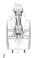
- the best mode for carrying out the invention is set forth in the context of a high bypass gas turbine aircraft engine shown schematically in Fig. 1.
- the engine includes a powerplant 2, a bladed propulsor or fan 4, and a drive system 6 for conveying rotary motion from the powerplant to the fan.
- the drive system is a geared drive system including a planetary gear train 8 and a torque transfer structure or torque frame 10.
- the power plant includes axial flow compressor 12 and 13 rotating about a longitudinally extending central axis 14 to compress intake air 3 and deliver it to a combustor 16 to be mixed with fuel (not shown) and ignited.
- Axial flow turbine 18 extracts energy from the hot combustion gases and, by means of shaft 21 drives compressor 13.
- turbine 19 drives compressor 12 by means of shaft 20.
- Fan 4 is also driven by turbine 19, however, a planetary gear train 8 and a torque frame 10 are located mechanically intermediate the shaft 20 and the fan 4. The fan imparts a modest acceleration to a large volume of air, thereby producing substantial forward thrust. Any energy not consumed in the turbine to drive the fan and compressor is converted to addition forward thrust in the exhaust nozzle 22.
- a sun gear 24 is rotatably driven by the shaft 20.
- a ring gear 26 is fixed to the engine static structure and remains stationary relative to the rotating sun gear.
- a plurality of planet gears 28 is rotatably mounted in a planet carrier 30 so that each planet gear is in meshing engagement with the sun gear and ring gear.
- the sun gear, planet carrier and ring gear share the common central axis 14 while the planet gears have individual axes of rotation 32.
- the sun gear and planet carrier are rotatable about the central axis while the ring gear is fixed relative thereto.
- the gears are bihelical to ensure smooth meshing and quiet operation, however, the invention is independent of the type of gears used, and simple spur gears are depicted in the Figures to ensure clarity of the disclosure.
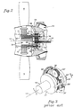
- a sun gear assembly 50 includes the forward portion 19 of the shaft 20 and the sun gear 24.
- a stationary ring gear assembly 52 includes the ring gear 26 and a nonrotating support structure 54 which may be the engine case or a mounting arrangement connecting the ring gear to the engine case.
- a planet gear assembly 56 includes the plurality of planet gears 28, a carrier 30 having a forward end plate 31 and a rear end plate 33, and planet gear journals 58 mounted in the carrier for rotatably supporting the planet gears.
- the carrier 30 also includes a plurality of apertures, one of which is shown at 76, circumferentially intermediate the planet gears 28.
- the sun gear assembly 50 is an input gear assembly since it is the component of the planetary gear train that receives rotary motion and torque from the powerplant 2 (Fig. 1).
- the planet gear assembly 56 is an output gear assembly since it is the component of the planetary gear train that transmits rotary motion and torque out of the planetary gear train to the fan.
- the torque frame 10 completes the connection from the planet carrier 30 to the bladed propulsor represented by fan blades 4 mounted in the periphery of a disk 70 whose bore 72 is adapted, as by a spline 71, to mate with the torque frame and rotate therewith.
- the torque frame has a circumferentially discontinuous first end 9, terminating in a series of discrete and therefore independently flexible arms 78, and a second end 11 spaced axially from the first end.
- Each arm has a proximal end 29 integral with the torque frame and a distal end 34.
- Each arm projects through a corresponding aperture 76 in the forward end plate 31.
- a joint 79 connects the carrier to the distal ends of the torque frame arms 78.
- the longitudinal centerline 35 of each arm is at a radius at least as great as that of the planet gear axes 32. Consequently, at least a portion of the distal end of each arm is at a radius greater than that of the planet gear axes.
- the torque frame 10 is connected to the rotating disk 70.
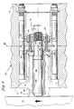
- Fig. 3 illustrates a geared drive system of conventional construction.
- the geared drive system includes a ring gear 26', a sun gear 24', planet gears 28', a planet carrier 30', and a torque frame 10'.
- the planet carrier 30' has a forward end plate 31' and a rear end plate 33'.
- Each planet gear is rotatably supported in the carrier by a journal 58', and each journal has a central axis 32' which is the axis of rotation of the associated planet gear.
- only one journal is shown and other structure connecting forward and rear end plates 31' and 33' has been omitted.
- the fan blades are not shown; instead they are represented by the torque T that they impose on the drive system.
- the powerplant rotates the sun gear, planet carrier, and torque frame in direction R, opposite to the direction of the torque load T.
- the torque frame is secured to the planet carrier so that the carrier experiences at least some of the torsional deflection occurring between the powerplant and the load.
- the torque frame is shown as a simple shaft secured to one end plate of the planet carrier. Many other constructions are possible including those in which the torque frame is integral with and indistinguishable from the carrier, however, they all share the characteristic that they transfer torsional deflection into the planet carrier. Consequently, the forward end plate 31' and rear end plate 33' of the planet carrier are circumferentially displaced relative to each other through an angle ⁇ .
- Each journal 58' is similarly deflected as shown in phantom so that the planet gear rotational axis 32' assumes a deflected orientation 32". Since the sun gear and ring gear axes remain parallel to the central axis 14' while the planet gear axes have become skewed or nonparallel relative thereto, the mesh between the planet gears and the sun gear, and the mesh between the planet gears and the ring gear deviate from the mesh that would have occurred had the axes remained parallel. If allowances are made in the gear tooth design to accommodate the effects of nonparallelism, they will only be completely effective at a single operating condition. Reinforcing the planetary gear train as by stiffening the carrier to minimize torsional deflection or by strengthening the gear teeth generally involves increased weight, cost, or physical size, all of which may be unacceptable.
- the present invention isolates the planet carrier from the effects of torsional deflection by transferring torque from the carrier to the torque frame such that substantially all of the torsional deflection is experienced in the torque frame, and substantially none of the torsional deflection occurs in the planet carrier.
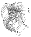
- Fig. 4 shows the forward end plate 31 and rear end plate 33 of the carrier 30 abuttingly mated together by carrier assembly bolts 90 (only two of which are shown). As best seen in Fig.'s 6 and 7, the abutting contact extends over a substantial portion of the circumference of the carrier.
- the mating surfaces of the carrier end plates define shoulders 93, and the forward end plate 31 of the carrier includes a series of apertures 76 circumferentially intermediate the sun gears.
- the torque frame 10 is circumferentially discontinuous, terminating in a series of discrete arms 78. Each arm extends axially through the apertures to a location axially intermediate the forward end plate 31 and rear end plate 33 of the carrier where each arm is connected to the carrier by a joint 79 mechanically intermediate the torque frame and the carrier.
- Joint 79 is a spherical bearing 80 comprising a housing 82 with a flange 83 and a truncated spherical ball 84 trapped within the housing, but capable of pivotable motion about both a radial axis 86 perpendicular to the plane of the illustration and a tangential axis 88.
- a housing attachment nut 92 threads onto the end of the housing opposite the flange 83 to clamp the housing 82 onto the shoulder 93 to secure the spherical bearing to the carrier.
- An attachment bolt 96 extends through a substantially axial first hole 98 in each torque frame arm and a second hole 99 in the ball. The attachment bolts 96 and mating nuts 94 effect the connection of each torque frame arm 78 to the articulating balls 84 and hence to the carrier 30.
- the torsional deflection or twisting of the torque frame is manifested as bending of the torque frame arms 78 from their undeflected position through an angle ⁇ ' to their deflected position 78" shown in phantom.
- the pivotability of the ball 84 about the radial axis 86 and the bending of the torque frame arms isolate the carrier 30 from torsional deflections.
- FIG. 5 shows one such connection where each torque frame arm 78 includes a radially extending hole 100 fitted with a pressed-in bushing 102.
- the carrier 30 includes corresponding holes 101, also fitted with bushings 103.
- a trunnion 104 radially disposed in the holes 101 in the carrier 30 and retained therein by a trunnion retention screw 105, extends through the hole 100 in the torque frame arms 78 to pivotably join the carrier and the torque frame.
- the torque frame arm 78 and the bushing 102 pivot about radial axis 86 while the trunnion remains stationary relative to the carrier.
- the trunnion connection accommodates bending of the torque frame arms in the tangential direction without imposing any twist or torsional deflection on the carrier.
- Fig. 6 illustrates, in simplified form, a planet carrier 30 rotating in direction R about the central axis 14.
- a distributed driving force 110 symmetrical about the axial midpoint 112 of the planet gears 28, represents the force conveyed to the carrier by the planet gear orbital motion.
- the distributed driving force which urges rotation of the carrier and, therefore, of the output gear assembly, can be represented by a resultant driving force 114 acting on the carrier at a location corresponding to the axial midpoint 112 of the planet gears.
- the carrier also experiences an individual reaction force 118 at each location 116 corresponding to the axial and circumferential position of each pivotable joint (not shown).
- the pivotable joints are axially positioned at locations 116 so that their individual reaction forces 118 all lie on a common plane perpendicular to the central axis 14 and located at the axial midpoint 112 of the planet gears. Consequently, the net resultant reaction force 120 corresponding to the individual reaction forces 118 also acts at the axial midpoint 112.
- the axial coincidence of the resultant reaction force 120 and the resultant driving force 114 at the axial midpoint 112 ensures that the carrier does not experience torsional deflection.
- the carrier will be subject to a twisting influence tending to diminish the benefits of the spherical bearing.
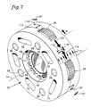
- Fig. 7 illustrates staggering of the joint positions 116 forward and rearward of the midpoint 112.
- the distributed driving force 110 symmetrical about the axial midpoint 112 of the planet gears, urges rotation of the carrier and, therefore, of the output gear assembly.
- the distributed driving force can be represented by a resultant driving force 114 acting on the carrier at a location corresponding to the axial midpoint 112 of the planet gears.
- Circumferentially neighboring joints (not shown) are positioned at locations 116', forwardly offset from the midpoint 112 by a distance d and 116" rearwardly offset from the midpoint by an equal distance d.
- the corresponding individual reaction forces 118' and 118" yield a resultant reaction force 120 acting at the midpoint 112 and axially coincident with the resultant driving force 114.
- the axial coincidence of the resultant reaction force 120 and the resultant driving force 114 at the axial midpoint 112 isolates the carrier from torsional deflection.
- the sun gear assembly 50 (Fig. 2) is the input gear assembly
- the planet gear assembly 56 is the output gear assembly
- the ring gear assembly is stationary.
- any one of these three gear assemblies can be the input, either of the remaining two gear assemblies can be the output and the remaining gear assembly can be stationary.
- the planet carrier is stationary and the ring gear rotates.
- the sun gear assembly is the input gear assembly
- the ring gear assembly rather than the planet gear assembly, is the output gear assembly.
- This gear arrangement requires the ring gear support structure 54 to be rotatable about the central axis 14, and the planet carrier 30 to be stationary.
- the torque frame connects the planet carrier, by way of pivotable joints as described hereinabove, to a stationary component, for example, the nonrotating support structure of a gas turbine engine, for reacting the torque being conveyed through the gear train.
- the distributed driving force 110 and its resultant 114 are still present but do not cause rotary motion of the carrier.
- Geared drive systems can also be arranged so that one of the sun gear assembly, ring gear assembly, and planet gear assembly is an input gear assembly but that both of the remaining gear assemblies are output gear assemblies.
- This single input, dual output arrangement also benefits from the present invention provided the planet carrier is connected to the torque frame proximate its first end with pivotable joints as described hereinabove.
Abstract
Claims (12)
- Système de transmission à engrenages pour un propulseur à pales, comprenant :
un train planétaire (8) incluant :un ensemble planétaire (50) comprenant un planétaire (24) ;un ensemble couronne de train planétaire (52) comprenant une couronne de train planétaire (26) ;un ensemble satellites (56) comprenant une pluralité de satellites (28) logés dans un porte-satellites (30) et disposés mécaniquement entre le planétaire (24) et la couronne de train planétaire (26) et en contact d'engrènement avec ceux-ci, le porte-satellites (30) comportant une plaque d'extrémité avant (31) et une plaque d'extrémité arrière (33) accouplées en butée, l'une avec l'autre, le contact en butée entre les plaques s'étendant sur une partie importante de la circonférence du porte-satellites, la plaque d'extrémité avant (31) comportant également une pluralité d'ouvertures (76) ;système dans lequel l'un de l'ensemble planétaire (50), de l'ensemble couronne de train planétaire (52) et de l'ensemble satellites (56), est un ensemble engrenage d'entrée recevant un couple d'une source de couple et au moins l'un restant de l'ensemble planétaire (50), de l'ensemble couronne de train planétaire (52), et de l'ensemble satellites (56) est un ensemble engrenage de sortie susceptible de délivrer le couple à une charge ; etune structure de transfert de couple (10) comportant une première extrémité (9) se terminant par une série de bras discrets flexibles individuellement (78), chaque bras comportant une extrémité proximale (29) et une extrémité distale (34), chaque bras (78) faisant saillie axialement à travers une ouverture de plaque d'extrémité correspondante (76), les extrémités distales (34) des bras (78) étant reliées à l'ensemble planétaire (56) par une pluralité d'articulations (79), au moins une partie de l'extrémité distale (34) de chaque bras étant à une distance radiale supérieure à celle des axes de satellites (32), chacune desdites articulations (79) se trouvant mécaniquement, par rapport à une trajectoire de charge passant par la couronne de train planétaire, entre la structure de transfert de couple (10) et l'ensemble satellites (56) dans lequel chaque articulation (79) peut pivoter autour d'au moins un axe radial (86). - Système de transmission à engrenages selon la revendication 1, dans lequel les articulations pivotantes (79) sont situées, par rapport au porte-satellites (30), de façon telle qu'une force de transmission résultante agissant sur le porte-satellites (30) et qu'une force de réaction résultante exercée par les articulations pivotantes (79) sur le porte-satellites (30) coïncident axialement.
- Système de transmission à engrenages selon la revendication 1 ou 2, dans lequel l'ensemble planétaire (50) est l'ensemble engrenage d'entrée, l'ensemble satellites (56) est l'ensemble engrenage de sortie et dans lequel l'ensemble couronne de train planétaire (52) est stationnaire par rapport à l'ensemble planétaire (50) et par rapport à l'ensemble satellites (56).
- Système de transmission à engrenages selon la revendication 1 ou 2, dans lequel l'ensemble planétaire (50) est l'ensemble engrenage d'entrée, l'ensemble couronne de train planétaire (52) est l'ensemble engrenage de sortie et dans lequel le porte-satellites (30) est stationnaire par rapport à l'ensemble planétaire (50) et par rapport à l'ensemble couronne de train planétaire (52).
- Système de transmission à engrenages selon la revendication 1 ou 2, dans lequel l'ensemble planétaire (50) est l'ensemble engrenage d'entrée, et dans lequel l'ensemble couronne de train planétaire (52) et l'ensemble satellites (56) sont les ensembles engrenages de sortie.
- Système de transmission à engrenages selon l'une quelconque des revendications 1 à 5, dans lequel les articulations (79) comprennent des paliers sphériques (80).
- Système de transmission à engrenages selon la revendication 6, dans lequel :une première extrémité de la structure de transfert de couple (10) se termine en une pluralité de bras (78) comportant chacun un premier trou sensiblement axial (98) les traversant ; etdans lequel chaque palier sphérique (80) comprend :un boîtier (82) fixé au porte-satellites (30) et stationnaire par rapport à celui-ci ;une boule (84) disposée à l'intérieur du boîtier (82) et capable d'un mouvement de pivotement par rapport à celui-ci, autour d'au moins l'axe radial (86), chaque boule étant également reliée à un bras correspondant de la pluralité de bras (78).
- Système de transmission à engrenages selon l'une quelconque des revendications 1 à 5, dans lequel :la première extrémité de la structure de transfert de couple (10) se termine en une pluralité de bras (78) comportant chacun un trou radial (100) les traversant ;dans lequel le porte-satellites (30) comprend une pluralité de trous radiaux correspondants (101) ; etdans lequel un tourillon (104) est disposé radialement dans chaque trou radial (100), et dans chaque trou correspondant (101) pour relier, de manière pivotante, le bâti de couple (10) au porte-satellites (30).
- Système de transmission à engrenages selon l'une quelconque des revendications précédentes, dans lequel, le planétaire (24), la couronne de train planétaire (52) et la pluralité de satellites (28) sont bihélicoïdaux.
- Système de transmission à engrenages pour un propulseur à pales, comprenant :
un train planétaire incluant :un ensemble planétaire (50) comprenant un planétaire (24) entraîné par une source de couple d'entrée ;un ensemble couronne de train planétaire (52) comprenant une couronne de train planétaire (26) stationnaire par rapport à l'ensemble planétaire (50) ;un ensemble satellites (56) comprenant une pluralité de satellites (28) supportés dans le porte-satellites (30) par des tourillons et disposés mécaniquement entre le planétaire (24) et la couronne de train planétaire (26) et en contact d'engrènement avec ceux-ci, de sorte que le porte-satellites (30) est forcé à tourner par une force de transmission résultante, le porte-satellites (30) comportant une plaque d'extrémité avant (31) et une plaque d'extrémité arrière (33) accouplées en butée, l'une avec l'autre, le contact en butée entre les plaques s'étendant sur une partie importante de la circonférence du porte-satellites (30), la plaque d'extrémité avant (31) comportant également une pluralité d'ouvertures (76) ;une structure de transfert de couple (10) pour entraîner une charge, la structure de transfert de couple (10) pouvant pivoter autour d'un axe central (14) et comportant une première extrémité (9) se terminant en une série de bras discrets flexibles individuellement (78), chaque bras comportant une extrémité proximale (29) et une extrémité distale (34), chaque bras faisant saillie axialement à travers une ouverture de plaque d'extrémité correspondante (76), au moins une partie de l'extrémité distale (34) de chaque bras (78) étant à une distance radiale supérieure à celle des axes de satellites (32), la structure de transfert de couple comportant également une seconde extrémité (11) reliée à un élément rotatif (4) ; etune pluralité d'articulations (79) disposées de manière circonférentielle par rapport au porte-satellites (30), chacune desdites articulations (79) se situant mécaniquement, par rapport à un trajet de charge passant par la couronne de train planétaire, entre la structure de transfert de couple (10) et l'ensemble satellites (56), et chaque articulation (79) pouvant pivoter autour d'au moins un axe radial (86) pour relier le porte-satellites (30) aux extrémités distales (34) des bras (78), chaque articulation (79) exerçant une force de réaction résultante sur le porte-satellites (30) et dans lequel les articulations (79) sont positionnées de manière axiale par rapport au porte-satelites (30) de façon telle que la force de réaction résultante coïncide, de manière axiale, avec la force de transmission résultante, au point central axial des satellites (28), de manière à transmettre, du porte-satellites aux bras, la force de transmission résultante sans imposer de déflexion en torsion au porte-satellites (30). - Système de transmission à engrenages pour un propulseur à pales, comprenant :
un train planétaire (8) incluant :un ensemble planétaire ( 5 0 ) comprenant un planétaire (24) entraîné par une source de couple d'entrée ;un ensemble couronne de train planétaire (52) comprenant une couronne de train planétaire (26) stationnaire par rapport à l'ensemble planétaire (50) ;un ensemble satellites (56) comprenant une pluralité de satellites (28) supportés dans un porte-satellites (30) par des tourillons et disposés mécaniquement entre le planétaire (24) et la couronne de train planétaire (26) et en contact d'engrènement avec ceux-ci, de sorte que le porte-satellites (30) est forcé à tourner par une force de transmission résultante, le porte-satellites (30) comportant une plaque d'extrémité avant (31) et une plaque d'extrémité arrière (33) accouplées en butée l'une avec l'autre, le contact en butée entre les plaques (31, 33) s'étendant sur une partie importante de la circonférence du porte-satellites (30), la plaque d'extrémité avant (31) comportant également une pluralité d'ouvertures (76) ;une structure de transfert de couple (10) pour entraîner une charge, la structure de transfert de couple (10) pouvant tourner autour d'un axe central (14) et comportant une première extrémité (9) se terminant en une série de bras discrets flexibles individuellement (78), chaque bras comportant une extrémité proximale (29) et une extrémité distale (34), chaque bras (78) faisant saillie axialement à travers une ouverture de plaque d'extrémité correspondante (76), au moins une partie de l'extrémité distale (34) de chaque bras (78) étant à une distance radiale supérieure à celle des axes de satellites (32), la structure de transfert de couple (10) comportant également une seconde extrémité reliée à un élément rotatif (11) ; etune pluralité d'articulations (79) disposées de manière circonférentielle par rapport au porte-satellites (30), chacune desdites articulations (79) se situant mécaniquement, par rapport à un trajet de charge passant par la couronne de train planétaire, entre la structure de transfert de couple (10) et l'ensemble satellites (56) et chaque articulation (79) pouvant pivoter autour d'au moins un axe radial (86) de façon à relier le porte-satellites (30) aux extrémités distales (34) des bras (78), chaque articulation (79) exerçant une force de réaction résultante sur le porte-satellites (30) et dans lequel les articulations (79) sont positionnées axialement par rapport au porte-satellites (30) sur un plan commun perpendiculaire à l'axe central (14) et sur la ligne centrale axiale (112) des satellites (28) afin de transmettre la force de transmission résultante du porte-satellites (30) aux bras (78) sans imposer de déflexion en torsion au porte-satellites (30). - Système de transmission à engrenages selon la revendication 10 ou 11, dans lequel l'ensemble planétaire solaire (50) est un ensemble engrenage d'entrée pour recevoir un couple d'une source de couple, dans lequel l'ensemble couronne de train planétaire (52) est un ensemble engrenage de sortie pour délivrer un couple à une charge, dans lequel le porte-satellites (30) est stationnaire, et dans lequel la seconde extrémité (11) de la structure de transfert de couple (10) est reliée à une structure non tournante.
Applications Claiming Priority (3)
| Application Number | Priority Date | Filing Date | Title |
|---|---|---|---|
| US75827 | 1993-06-11 | ||
| US08/075,827 US5466198A (en) | 1993-06-11 | 1993-06-11 | Geared drive system for a bladed propulsor |
| PCT/US1994/006507 WO1994029614A1 (fr) | 1993-06-11 | 1994-06-08 | Systeme de transmission a engrenages pour un propulseur a pales |
Publications (2)
| Publication Number | Publication Date |
|---|---|
| EP0701669A1 EP0701669A1 (fr) | 1996-03-20 |
| EP0701669B1 true EP0701669B1 (fr) | 1997-01-02 |
Family
ID=22128237
Family Applications (1)
| Application Number | Title | Priority Date | Filing Date |
|---|---|---|---|
| EP94919431A Expired - Lifetime EP0701669B1 (fr) | 1993-06-11 | 1994-06-08 | Systeme de transmission a engrenages pour un propulseur a pales |
Country Status (5)
| Country | Link |
|---|---|
| US (1) | US5466198A (fr) |
| EP (1) | EP0701669B1 (fr) |
| JP (1) | JP3497509B2 (fr) |
| DE (1) | DE69401357T2 (fr) |
| WO (1) | WO1994029614A1 (fr) |
Families Citing this family (224)
| Publication number | Priority date | Publication date | Assignee | Title |
|---|---|---|---|---|
| DE29609794U1 (de) * | 1996-06-03 | 1996-08-22 | Aerodyn Gmbh | Getriebe-Generator-Kombination |
| FI108959B (fi) | 1998-06-18 | 2002-04-30 | Valmet Voimansiirto Oy | Tuulivoimalan planeettavaihteisto |
| DE19844843B4 (de) * | 1998-09-30 | 2006-02-09 | Mtu Aero Engines Gmbh | Planetengetriebe |
| US6223616B1 (en) * | 1999-12-22 | 2001-05-01 | United Technologies Corporation | Star gear system with lubrication circuit and lubrication method therefor |
| US6663530B2 (en) * | 2001-12-14 | 2003-12-16 | Pratt & Whitney Canada Corp. | Zero twist carrier |
| US6964155B2 (en) * | 2002-12-30 | 2005-11-15 | United Technologies Corporation | Turbofan engine comprising an spicyclic transmission having bearing journals |
| FR2853382B1 (fr) * | 2003-04-04 | 2006-04-28 | Hispano Suiza Sa | Systeme de liaison souple entre un porte-satellites et le support fixe dans un reducteur de vitesse |
| US7104918B2 (en) * | 2003-07-29 | 2006-09-12 | Pratt & Whitney Canada Corp. | Compact epicyclic gear carrier |
| DE10334459A1 (de) * | 2003-07-29 | 2005-03-17 | Zf Friedrichshafen Ag | Führungsscheibenverbund eines Planetenträgers für ein Planetengetriebe |
| EP1834067B1 (fr) * | 2004-12-01 | 2008-11-26 | United Technologies Corporation | Ensemble de pales de soufflante pour moteur a turbine de bout et procede de montage |
| US8757959B2 (en) * | 2004-12-01 | 2014-06-24 | United Technologies Corporation | Tip turbine engine comprising a nonrotable compartment |
| EP1828547B1 (fr) | 2004-12-01 | 2011-11-30 | United Technologies Corporation | Turbosoufflante comprenant une pluralité d'aubes directrices d'entrée commandées individuellement et procédé de commande associé |
| WO2006060006A1 (fr) | 2004-12-01 | 2006-06-08 | United Technologies Corporation | Cone arriere non metallique de moteur a turbine de bout |
| US8024931B2 (en) | 2004-12-01 | 2011-09-27 | United Technologies Corporation | Combustor for turbine engine |
| WO2006059995A1 (fr) * | 2004-12-01 | 2006-06-08 | United Technologies Corporation | Systeme de lubrification de boite de vitesses pour moteur a turbine d'extremite |
| US8152469B2 (en) * | 2004-12-01 | 2012-04-10 | United Technologies Corporation | Annular turbine ring rotor |
| EP1819907A2 (fr) * | 2004-12-01 | 2007-08-22 | United Technologies Corporation | Pale de ventilateur comprenant une section de diffuseur integrale et une section de pale de turbine a aube destine a une moteur a turbine a aube |
| WO2006059970A2 (fr) * | 2004-12-01 | 2006-06-08 | United Technologies Corporation | Moteur a turbine equipe d'un ventilateur et d'un compresseur entraines par un engrenage differentiel |
| WO2006059969A1 (fr) * | 2004-12-01 | 2006-06-08 | United Technologies Corporation | Carter de compresseur à rotation inverse et procédé d'assemblage pour un moteur à turbine en bout |
| US7883315B2 (en) * | 2004-12-01 | 2011-02-08 | United Technologies Corporation | Seal assembly for a fan rotor of a tip turbine engine |
| US8033094B2 (en) * | 2004-12-01 | 2011-10-11 | United Technologies Corporation | Cantilevered tip turbine engine |
| EP1825113B1 (fr) * | 2004-12-01 | 2012-10-24 | United Technologies Corporation | Boîte de vitesses contre-rotative pour moteur à turbine en bout |
| US7927075B2 (en) * | 2004-12-01 | 2011-04-19 | United Technologies Corporation | Fan-turbine rotor assembly for a tip turbine engine |
| WO2006059975A1 (fr) | 2004-12-01 | 2006-06-08 | United Technologies Corporation | Foyer peripherique pour moteur a turbine de bout |
| WO2006059980A2 (fr) | 2004-12-01 | 2006-06-08 | United Technologies Corporation | Aspiration par diffuseur pour moteur a turbine d'extremite |
| DE602004019709D1 (de) | 2004-12-01 | 2009-04-09 | United Technologies Corp | Tip-turbinentriebwerk und entsprechendes betriebsverfahren |
| US9003759B2 (en) | 2004-12-01 | 2015-04-14 | United Technologies Corporation | Particle separator for tip turbine engine |
| WO2006060009A1 (fr) * | 2004-12-01 | 2006-06-08 | United Technologies Corporation | Moteur à aubes de turbine comprenant des groupes d'aubes et une disposition de blocage de fixation radial pour ceux-ci |
| US7976273B2 (en) * | 2004-12-01 | 2011-07-12 | United Technologies Corporation | Tip turbine engine support structure |
| WO2006059993A1 (fr) | 2004-12-01 | 2006-06-08 | United Technologies Corporation | Moteur à turbine en bout avec étages soufflante et turbine multiples |
| WO2006059985A1 (fr) | 2004-12-01 | 2006-06-08 | United Technologies Corporation | Compresseur axial pour moteur a turbine de bout |
| US20080219833A1 (en) * | 2004-12-01 | 2008-09-11 | United Technologies Corporation | Inducer for a Fan Blade of a Tip Turbine Engine |
| WO2006060005A1 (fr) * | 2004-12-01 | 2006-06-08 | United Technologies Corporation | Ensemble de rotor de turbine-ventilateur avec section d’induction integrale pour moteur de turbine a pression d’entree |
| US7883314B2 (en) * | 2004-12-01 | 2011-02-08 | United Technologies Corporation | Seal assembly for a fan-turbine rotor of a tip turbine engine |
| DE602004031679D1 (de) * | 2004-12-01 | 2011-04-14 | United Technologies Corp | Regenerative Kühlung einer Leit- und Laufschaufel für ein Tipturbinentriebwerk |
| WO2006059971A2 (fr) * | 2004-12-01 | 2006-06-08 | United Technologies Corporation | Logement de moteur a turbine integrant un ventilateur, un combustor, et une turbine |
| WO2006059996A1 (fr) * | 2004-12-01 | 2006-06-08 | United Technologies Corporation | Ailettes de rotor de soufflante pour moteur a turbine en bout |
| US7631480B2 (en) * | 2004-12-01 | 2009-12-15 | United Technologies Corporation | Modular tip turbine engine |
| EP1831530B1 (fr) * | 2004-12-01 | 2009-02-25 | United Technologies Corporation | Commande à distance d'étage variable de compresseur pour moteur à turbine |
| EP1831521B1 (fr) | 2004-12-01 | 2008-08-20 | United Technologies Corporation | Ensemble aubes de guidage d'admission de soufflante variable, turbomachine dotee d'un tel ensemble et procede de commande correspondant |
| EP1841960B1 (fr) * | 2004-12-01 | 2011-05-25 | United Technologies Corporation | Ailettes de rotor de soufflante pour moteur a turbine en bout |
| EP1828573B1 (fr) * | 2004-12-01 | 2010-06-16 | United Technologies Corporation | Joint hydraulique pour boite de vitesses de moteur a turbine d'extremite |
| EP1825116A2 (fr) | 2004-12-01 | 2007-08-29 | United Technologies Corporation | Refroidissement par ejecteur de l'enveloppe exterieure d'un moteur a turbine de bout |
| US7882695B2 (en) | 2004-12-01 | 2011-02-08 | United Technologies Corporation | Turbine blow down starter for turbine engine |
| US8096753B2 (en) * | 2004-12-01 | 2012-01-17 | United Technologies Corporation | Tip turbine engine and operating method with reverse core airflow |
| US7976272B2 (en) | 2004-12-01 | 2011-07-12 | United Technologies Corporation | Inflatable bleed valve for a turbine engine |
| EP1825126B1 (fr) | 2004-12-01 | 2011-02-16 | United Technologies Corporation | Conduit de transition pour moteur a turbine |
| US7631485B2 (en) | 2004-12-01 | 2009-12-15 | United Technologies Corporation | Tip turbine engine with a heat exchanger |
| WO2006059979A1 (fr) * | 2004-12-01 | 2006-06-08 | United Technologies Corporation | Carter intégral, aube fixe, bâti et mélangeur d'un moteur à turbine en bout |
| EP1828574B1 (fr) * | 2004-12-01 | 2010-11-03 | United Technologies Corporation | Ensemble de boite de vitesses a couplage proximal pour moteur de turbine a pression d'entree |
| WO2006110125A2 (fr) | 2004-12-01 | 2006-10-19 | United Technologies Corporation | Elements annulaires empiles pour moteurs a turbine |
| WO2006062497A1 (fr) * | 2004-12-04 | 2006-06-15 | United Technologies Corporation | Bâti moteur à turbine en bout de pale |
| US8267826B2 (en) * | 2005-03-15 | 2012-09-18 | United Technologies Corporation | Uninterruptible oil supply in planetary system |
| US8667688B2 (en) | 2006-07-05 | 2014-03-11 | United Technologies Corporation | Method of assembly for gas turbine fan drive gear system |
| US8585538B2 (en) | 2006-07-05 | 2013-11-19 | United Technologies Corporation | Coupling system for a star gear train in a gas turbine engine |
| US7704178B2 (en) * | 2006-07-05 | 2010-04-27 | United Technologies Corporation | Oil baffle for gas turbine fan drive gear system |
| US9194255B2 (en) | 2006-07-05 | 2015-11-24 | United Technologies Corporation | Oil baffle for gas turbine fan drive gear system |
| US7926260B2 (en) * | 2006-07-05 | 2011-04-19 | United Technologies Corporation | Flexible shaft for gas turbine engine |
| US8939864B2 (en) | 2006-08-15 | 2015-01-27 | United Technologies Corporation | Gas turbine engine lubrication |
| US10107231B2 (en) | 2006-08-15 | 2018-10-23 | United Technologies Corporation | Gas turbine engine with geared architecture |
| US9976437B2 (en) | 2006-08-15 | 2018-05-22 | United Technologies Corporation | Epicyclic gear train |
| US8753243B2 (en) | 2006-08-15 | 2014-06-17 | United Technologies Corporation | Ring gear mounting arrangement with oil scavenge scheme |
| US20120213628A1 (en) | 2006-08-15 | 2012-08-23 | Mccune Michael E | Gas turbine engine with geared architecture |
| US8858388B2 (en) | 2006-08-15 | 2014-10-14 | United Technologies Corporation | Gas turbine engine gear train |
| US8708863B2 (en) | 2006-08-15 | 2014-04-29 | United Technologies Corporation | Epicyclic gear train |
| WO2008045072A1 (fr) | 2006-10-12 | 2008-04-17 | United Technologies Corporation | Buse d'éjection à section variable intégrée à double cascade de fonctions et inverseur de poussée |
| US7849668B2 (en) * | 2006-10-25 | 2010-12-14 | United Technologies Corporation | Rotor brake and windmilling lubrication system for geared turbofan engine |
| US20080273961A1 (en) | 2007-03-05 | 2008-11-06 | Rosenkrans William E | Flutter sensing and control system for a gas turbine engine |
| US8967945B2 (en) | 2007-05-22 | 2015-03-03 | United Technologies Corporation | Individual inlet guide vane control for tip turbine engine |
| US11346289B2 (en) | 2007-08-01 | 2022-05-31 | Raytheon Technologies Corporation | Turbine section of high bypass turbofan |
| US11149650B2 (en) | 2007-08-01 | 2021-10-19 | Raytheon Technologies Corporation | Turbine section of high bypass turbofan |
| US11486311B2 (en) | 2007-08-01 | 2022-11-01 | Raytheon Technologies Corporation | Turbine section of high bypass turbofan |
| US11242805B2 (en) | 2007-08-01 | 2022-02-08 | Raytheon Technologies Corporation | Turbine section of high bypass turbofan |
| US20150377123A1 (en) | 2007-08-01 | 2015-12-31 | United Technologies Corporation | Turbine section of high bypass turbofan |
| US9701415B2 (en) | 2007-08-23 | 2017-07-11 | United Technologies Corporation | Gas turbine engine with axial movable fan variable area nozzle |
| US9957918B2 (en) * | 2007-08-28 | 2018-05-01 | United Technologies Corporation | Gas turbine engine front architecture |
| US20140157754A1 (en) | 2007-09-21 | 2014-06-12 | United Technologies Corporation | Gas turbine engine compressor arrangement |
| US8205432B2 (en) * | 2007-10-03 | 2012-06-26 | United Technologies Corporation | Epicyclic gear train for turbo fan engine |
| US10151248B2 (en) | 2007-10-03 | 2018-12-11 | United Technologies Corporation | Dual fan gas turbine engine and gear train |
| ES2376960T3 (es) * | 2007-10-22 | 2012-03-21 | Vestas Wind Systems A/S | Etapa de engranajes epicicloidales para una caja de engranajes de turbina eólica, caja de engranajes de turbina eólica y turbina eólica |
| ES2364319T3 (es) * | 2007-12-20 | 2011-08-31 | Vestas Wind Systems A/S | Etapa de engranajes epicíclicos para una caja de engranajes de turbina eólica, caja de engranajes de turbina eólica y turbina eólica. |
| US8348803B2 (en) * | 2008-04-17 | 2013-01-08 | Kawasaki Jukogyo Kabushiki Kaisha | Planetary reduction gear apparatus |
| US20140174056A1 (en) | 2008-06-02 | 2014-06-26 | United Technologies Corporation | Gas turbine engine with low stage count low pressure turbine |
| DE102008063044B4 (de) * | 2008-12-23 | 2012-01-05 | Aerodyn Engineering Gmbh | Planetengetriebe |
| US9885313B2 (en) | 2009-03-17 | 2018-02-06 | United Technologes Corporation | Gas turbine engine bifurcation located fan variable area nozzle |
| CA2682454C (fr) | 2009-04-14 | 2013-11-26 | Kawasaki Jukogyo Kabushiki Kaisha | Appareil a demultiplicateurs planetaires |
| US8689538B2 (en) | 2009-09-09 | 2014-04-08 | The Boeing Company | Ultra-efficient propulsor with an augmentor fan circumscribing a turbofan |
| JP4975081B2 (ja) | 2009-10-30 | 2012-07-11 | 川崎重工業株式会社 | 遊星歯車減速装置 |
| US8672801B2 (en) | 2009-11-30 | 2014-03-18 | United Technologies Corporation | Mounting system for a planetary gear train in a gas turbine engine |
| IT1401662B1 (it) | 2010-08-27 | 2013-08-02 | Nuova Pignone S R L | Dispositivo espansore multistadio assiale con ingranaggi, sistema e metodo. |
| US8813469B2 (en) | 2010-10-12 | 2014-08-26 | United Technologies Corporation | Planetary gear system arrangement with auxiliary oil system |
| US9995174B2 (en) | 2010-10-12 | 2018-06-12 | United Technologies Corporation | Planetary gear system arrangement with auxiliary oil system |
| US10605167B2 (en) | 2011-04-15 | 2020-03-31 | United Technologies Corporation | Gas turbine engine front center body architecture |
| US8777793B2 (en) * | 2011-04-27 | 2014-07-15 | United Technologies Corporation | Fan drive planetary gear system integrated carrier and torque frame |
| US8900083B2 (en) | 2011-04-27 | 2014-12-02 | United Technologies Corporation | Fan drive gear system integrated carrier and torque frame |
| US9239012B2 (en) | 2011-06-08 | 2016-01-19 | United Technologies Corporation | Flexible support structure for a geared architecture gas turbine engine |
| US9523422B2 (en) | 2011-06-08 | 2016-12-20 | United Technologies Corporation | Flexible support structure for a geared architecture gas turbine engine |
| US9631558B2 (en) | 2012-01-03 | 2017-04-25 | United Technologies Corporation | Geared architecture for high speed and small volume fan drive turbine |
| US9909505B2 (en) | 2011-07-05 | 2018-03-06 | United Technologies Corporation | Efficient, low pressure ratio propulsor for gas turbine engines |
| US9506422B2 (en) | 2011-07-05 | 2016-11-29 | United Technologies Corporation | Efficient, low pressure ratio propulsor for gas turbine engines |
| US9938898B2 (en) | 2011-07-29 | 2018-04-10 | United Technologies Corporation | Geared turbofan bearing arrangement |
| ITTO20111007A1 (it) * | 2011-11-03 | 2013-05-04 | Avio Spa | Rotismo epicicloidale |
| EP2610461B1 (fr) | 2011-12-30 | 2019-10-23 | United Technologies Corporation | Moteur à turbine |
| US9416677B2 (en) | 2012-01-10 | 2016-08-16 | United Technologies Corporation | Gas turbine engine forward bearing compartment architecture |
| US20130186058A1 (en) | 2012-01-24 | 2013-07-25 | William G. Sheridan | Geared turbomachine fan and compressor rotation |
| US8869508B2 (en) | 2012-01-31 | 2014-10-28 | United Technologies Corporation | Gas turbine engine variable area fan nozzle control |
| US10400629B2 (en) | 2012-01-31 | 2019-09-03 | United Technologies Corporation | Gas turbine engine shaft bearing configuration |
| US9835052B2 (en) | 2012-01-31 | 2017-12-05 | United Technologies Corporation | Gas turbine engine with high speed low pressure turbine section and bearing support features |
| US10113434B2 (en) | 2012-01-31 | 2018-10-30 | United Technologies Corporation | Turbine blade damper seal |
| US10415468B2 (en) | 2012-01-31 | 2019-09-17 | United Technologies Corporation | Gas turbine engine buffer system |
| US9394852B2 (en) | 2012-01-31 | 2016-07-19 | United Technologies Corporation | Variable area fan nozzle with wall thickness distribution |
| US20130192191A1 (en) | 2012-01-31 | 2013-08-01 | Frederick M. Schwarz | Gas turbine engine with high speed low pressure turbine section and bearing support features |
| US20150192070A1 (en) | 2012-01-31 | 2015-07-09 | United Technologies Corporation | Geared turbofan gas turbine engine architecture |
| US20130192251A1 (en) | 2012-01-31 | 2013-08-01 | Peter M. Munsell | Buffer system that communicates buffer supply air to one or more portions of a gas turbine engine |
| US8863491B2 (en) | 2012-01-31 | 2014-10-21 | United Technologies Corporation | Gas turbine engine shaft bearing configuration |
| US8935913B2 (en) | 2012-01-31 | 2015-01-20 | United Technologies Corporation | Geared turbofan gas turbine engine architecture |
| US20130192240A1 (en) | 2012-01-31 | 2013-08-01 | Peter M. Munsell | Buffer system for a gas turbine engine |
| US10724431B2 (en) | 2012-01-31 | 2020-07-28 | Raytheon Technologies Corporation | Buffer system that communicates buffer supply air to one or more portions of a gas turbine engine |
| US10287914B2 (en) | 2012-01-31 | 2019-05-14 | United Technologies Corporation | Gas turbine engine with high speed low pressure turbine section and bearing support features |
| US8720306B2 (en) | 2012-01-31 | 2014-05-13 | United Technologies Corporation | Turbine engine gearbox |
| US20130192198A1 (en) | 2012-01-31 | 2013-08-01 | Lisa I. Brilliant | Compressor flowpath |
| US20150345426A1 (en) | 2012-01-31 | 2015-12-03 | United Technologies Corporation | Geared turbofan gas turbine engine architecture |
| US9169781B2 (en) | 2012-01-31 | 2015-10-27 | United Technologies Corporation | Turbine engine gearbox |
| US10107191B2 (en) | 2012-02-29 | 2018-10-23 | United Technologies Corporation | Geared gas turbine engine with reduced fan noise |
| EP3855003B1 (fr) * | 2012-03-23 | 2022-09-28 | Raytheon Technologies Corporation | Agencement de système d'engrenage planétaire ayant un système d'huile auxiliaire |
| US8961112B2 (en) * | 2012-03-26 | 2015-02-24 | United Technologies Corporation | Torque frame bushing arrangement for gas turbine engine fan drive gear system |
| US8790075B2 (en) | 2012-03-30 | 2014-07-29 | United Technologies Corporation | Gas turbine engine geared architecture axial retention arrangement |
| US20130255275A1 (en) | 2012-04-02 | 2013-10-03 | Frederick M. Schwarz | Geared turbofan engine with power density range |
| US10125693B2 (en) | 2012-04-02 | 2018-11-13 | United Technologies Corporation | Geared turbofan engine with power density range |
| US10138809B2 (en) | 2012-04-02 | 2018-11-27 | United Technologies Corporation | Geared turbofan engine with a high ratio of thrust to turbine volume |
| US8585536B2 (en) | 2012-04-02 | 2013-11-19 | Hamilton Sundstrand Corporation | Gear carrier frame |
| US20130269479A1 (en) * | 2012-04-11 | 2013-10-17 | General Electric Company | Gearbox and support apparatus for gearbox carrier |
| JP5915352B2 (ja) * | 2012-04-19 | 2016-05-11 | トヨタ自動車株式会社 | 変速機を備えたターボプロップ/ファン型ジェットエンジン |
| US8484942B1 (en) | 2012-05-30 | 2013-07-16 | United Technologies Corporation | Planetary gear system arrangement with auxiliary oil system |
| US8572943B1 (en) | 2012-05-31 | 2013-11-05 | United Technologies Corporation | Fundamental gear system architecture |
| US20150308351A1 (en) | 2012-05-31 | 2015-10-29 | United Technologies Corporation | Fundamental gear system architecture |
| US9267389B2 (en) | 2012-06-05 | 2016-02-23 | United Technologies Corporation | Geared architecture carrier torque frame assembly |
| US8727935B2 (en) | 2012-07-30 | 2014-05-20 | United Technologies Corporation | Fan drive gear system torque frame pin retainer |
| US9328818B2 (en) | 2012-09-21 | 2016-05-03 | United Technologies Corporation | Gear carrier flex mount lubrication |
| US8753065B2 (en) | 2012-09-27 | 2014-06-17 | United Technologies Corporation | Method for setting a gear ratio of a fan drive gear system of a gas turbine engine |
| US8807916B2 (en) | 2012-09-27 | 2014-08-19 | United Technologies Corporation | Method for setting a gear ratio of a fan drive gear system of a gas turbine engine |
| WO2014051672A1 (fr) | 2012-09-28 | 2014-04-03 | United Technologies Corporation | Tube en t de mesure de débit en zones séparées |
| EP3690211A1 (fr) | 2012-10-08 | 2020-08-05 | United Technologies Corporation | Moteur à turbine à engrenages doté d'un module de propulsion relativement léger |
| US11280271B2 (en) | 2012-10-09 | 2022-03-22 | Raytheon Technologies Corporation | Operability geared turbofan engine including compressor section variable guide vanes |
| US9932933B2 (en) | 2012-12-20 | 2018-04-03 | United Technologies Corporation | Low pressure ratio fan engine having a dimensional relationship between inlet and fan size |
| US9920653B2 (en) | 2012-12-20 | 2018-03-20 | United Technologies Corporation | Low pressure ratio fan engine having a dimensional relationship between inlet and fan size |
| US8678743B1 (en) | 2013-02-04 | 2014-03-25 | United Technologies Corporation | Method for setting a gear ratio of a fan drive gear system of a gas turbine engine |
| US10436120B2 (en) | 2013-02-06 | 2019-10-08 | United Technologies Corporation | Exhaust nozzle for an elongated gear turbofan with high bypass ratio |
| US9863326B2 (en) | 2013-03-12 | 2018-01-09 | United Technologies Corporation | Flexible coupling for geared turbine engine |
| US11719161B2 (en) | 2013-03-14 | 2023-08-08 | Raytheon Technologies Corporation | Low noise turbine for geared gas turbine engine |
| US10605172B2 (en) | 2013-03-14 | 2020-03-31 | United Technologies Corporation | Low noise turbine for geared gas turbine engine |
| US9885282B2 (en) | 2013-03-15 | 2018-02-06 | United Technologies Corporation | Turbofan engine bearing and gearbox arrangement |
| US10724479B2 (en) | 2013-03-15 | 2020-07-28 | United Technologies Corporation | Thrust efficient turbofan engine |
| EP2994628A4 (fr) | 2013-05-09 | 2017-01-18 | United Technologies Corporation | Section avant de moteur à turboréacteur |
| EP3957847A1 (fr) | 2013-05-09 | 2022-02-23 | Raytheon Technologies Corporation | Section avant de moteur à turboréacteur |
| US9745862B2 (en) | 2013-08-21 | 2017-08-29 | United Technologies Corporation | Reduced misalignment gear system |
| US8857149B1 (en) * | 2013-08-26 | 2014-10-14 | United Technologies Corporation | Torque connector lubrication scuppers |
| EP3363736B1 (fr) | 2013-09-05 | 2020-07-15 | Airbus Operations Limited | Interface flexible de système d'entraînement de train d'atterrissage |
| CN105517895B (zh) * | 2013-09-05 | 2017-10-27 | 空中客车营运有限公司 | 起落架驱动系统柔性接合装置 |
| US10371047B2 (en) | 2013-10-16 | 2019-08-06 | United Technologies Corporation | Geared turbofan engine with targeted modular efficiency |
| WO2015112212A2 (fr) | 2013-11-01 | 2015-07-30 | United Technologies Corporation | Agencement de réacteur à réducteur présentant un rapport de puissance divisé par noyau |
| US10502163B2 (en) | 2013-11-01 | 2019-12-10 | United Technologies Corporation | Geared turbofan arrangement with core split power ratio |
| US8869504B1 (en) | 2013-11-22 | 2014-10-28 | United Technologies Corporation | Geared turbofan engine gearbox arrangement |
| US10161409B2 (en) | 2013-12-30 | 2018-12-25 | United Technologies Corporation | Fan drive gear system including a two-piece fan shaft with lubricant transfer leakage recapture |
| CN103742377A (zh) * | 2014-01-07 | 2014-04-23 | 丁兴龙 | 定向力发生装置 |
| EP3097324B1 (fr) | 2014-01-20 | 2019-04-03 | United Technologies Corporation | Élément de poids léger formant broche de support pour tourillons |
| US10502229B2 (en) | 2014-02-19 | 2019-12-10 | United Technologies Corporation | Gas turbine engine airfoil |
| WO2015126454A1 (fr) | 2014-02-19 | 2015-08-27 | United Technologies Corporation | Surface portante de moteur à turbine à gaz |
| EP3108121B1 (fr) | 2014-02-19 | 2023-09-06 | Raytheon Technologies Corporation | Moteur à double flux à engrenage avec aubes de compresseur basse pression |
| US10465702B2 (en) | 2014-02-19 | 2019-11-05 | United Technologies Corporation | Gas turbine engine airfoil |
| EP3108113A4 (fr) | 2014-02-19 | 2017-03-15 | United Technologies Corporation | Profil aérodynamique de turbine à gaz |
| US10557477B2 (en) | 2014-02-19 | 2020-02-11 | United Technologies Corporation | Gas turbine engine airfoil |
| US10605259B2 (en) | 2014-02-19 | 2020-03-31 | United Technologies Corporation | Gas turbine engine airfoil |
| EP3108107B1 (fr) | 2014-02-19 | 2023-10-11 | Raytheon Technologies Corporation | Moteur à double flux à engrenage avec aubes de compresseur basse pression |
| US10570916B2 (en) | 2014-02-19 | 2020-02-25 | United Technologies Corporation | Gas turbine engine airfoil |
| US9599064B2 (en) | 2014-02-19 | 2017-03-21 | United Technologies Corporation | Gas turbine engine airfoil |
| EP3108106B1 (fr) | 2014-02-19 | 2022-05-04 | Raytheon Technologies Corporation | Pale de moteur à turbine à gaz |
| US10280843B2 (en) | 2014-03-07 | 2019-05-07 | United Technologies Corporation | Geared turbofan with integral front support and carrier |
| US9879608B2 (en) * | 2014-03-17 | 2018-01-30 | United Technologies Corporation | Oil loss protection for a fan drive gear system |
| US11448123B2 (en) | 2014-06-13 | 2022-09-20 | Raytheon Technologies Corporation | Geared turbofan architecture |
| US9976490B2 (en) | 2014-07-01 | 2018-05-22 | United Technologies Corporation | Geared gas turbine engine with oil deaerator |
| US10060289B2 (en) | 2014-07-29 | 2018-08-28 | United Technologies Corporation | Geared gas turbine engine with oil deaerator and air removal |
| US10221771B2 (en) | 2014-09-24 | 2019-03-05 | United Technologies Corporation | Fan drive gear system |
| GB201417505D0 (en) | 2014-10-03 | 2014-11-19 | Rolls Royce Deutschland | A gas turbine architecture |
| GB201417504D0 (en) * | 2014-10-03 | 2014-11-19 | Rolls Royce Deutschland | A gas turbine architecture |
| US11067005B2 (en) | 2015-02-03 | 2021-07-20 | Raytheon Technologies Corporation | Fan drive gear system |
| US9879694B2 (en) | 2015-02-03 | 2018-01-30 | United Technologies Corporation | Turbo-compressor with geared turbofan |
| US9915225B2 (en) | 2015-02-06 | 2018-03-13 | United Technologies Corporation | Propulsion system arrangement for turbofan gas turbine engine |
| US9470093B2 (en) | 2015-03-18 | 2016-10-18 | United Technologies Corporation | Turbofan arrangement with blade channel variations |
| US10371168B2 (en) | 2015-04-07 | 2019-08-06 | United Technologies Corporation | Modal noise reduction for gas turbine engine |
| US9874145B2 (en) | 2015-04-27 | 2018-01-23 | United Technologies Corporation | Lubrication system for gas turbine engines |
| US10458270B2 (en) | 2015-06-23 | 2019-10-29 | United Technologies Corporation | Roller bearings for high ratio geared turbofan engine |
| GB2542338B (en) | 2015-09-10 | 2018-11-21 | Rolls Royce Plc | Gear trains |
| US10415429B2 (en) | 2015-09-25 | 2019-09-17 | General Electric Company | Planet gearbox with cylindrical roller bearing with high density roller packing |
| US20170089218A1 (en) * | 2015-09-25 | 2017-03-30 | General Electric Company | Double row cylindrical roller bearing with high length to diameter ratio rollers |
| DE102015118669B4 (de) | 2015-10-30 | 2023-03-16 | Rolls-Royce Deutschland Ltd & Co Kg | Strahltriebwerk mit einem Bläser und mit einer Turbineneinrichtung |
| US10233773B2 (en) | 2015-11-17 | 2019-03-19 | United Technologies Corporation | Monitoring system for non-ferrous metal particles |
| US10508562B2 (en) | 2015-12-01 | 2019-12-17 | United Technologies Corporation | Geared turbofan with four star/planetary gear reduction |
| US10066734B2 (en) | 2015-12-07 | 2018-09-04 | United Technologies Corporation | Gear driven gas turbine engine assembly |
| GB2548140B (en) * | 2016-03-10 | 2019-05-29 | Rolls Royce Plc | Transmission system |
| FR3052213B1 (fr) * | 2016-06-07 | 2018-05-18 | Safran Transmission Systems | Procede d'assemblage d'un porte-satellites |
| EP3263952B1 (fr) | 2016-06-29 | 2019-11-27 | Rolls-Royce Deutschland Ltd & Co KG | Structure porteuse pour un entraînement par engrenage planétaire, ledit entraînement et turbomachine dotée de ce dernier |
| US10669948B2 (en) | 2017-01-03 | 2020-06-02 | Raytheon Technologies Corporation | Geared turbofan with non-epicyclic gear reduction system |
| IT201700029839A1 (it) * | 2017-03-17 | 2018-09-17 | Ge Avio Srl | Porta-satelliti per un rotismo epicicloidale e rotismo epicicloidale provvisto di tale porta-satelliti |
| US10738646B2 (en) | 2017-06-12 | 2020-08-11 | Raytheon Technologies Corporation | Geared turbine engine with gear driving low pressure compressor and fan at common speed, and failsafe overspeed protection and shear section |
| US10662879B2 (en) | 2017-08-08 | 2020-05-26 | Pratt & Whitney Canada Corp. | Epicyclic gear stage |
| FR3073915B1 (fr) * | 2017-11-17 | 2019-10-25 | Safran Transmission Systems | Cage de reducteur de vitesse a train planetaire ou epicycloidal de turbomachine |
| US10724445B2 (en) | 2018-01-03 | 2020-07-28 | Raytheon Technologies Corporation | Method of assembly for fan drive gear system with rotating carrier |
| US10927944B2 (en) | 2018-01-26 | 2021-02-23 | Pratt & Whitney Canada Corp. | Compact, twist controlled planet carrier and epicyclic gear train having same |
| US10760677B2 (en) | 2018-01-31 | 2020-09-01 | Pratt & Whitney Canada Corp. | Epicyclic gear train with balanced carrier stiffness |
| DE102018106564B4 (de) * | 2018-03-20 | 2024-03-21 | Rolls-Royce Deutschland Ltd & Co Kg | Planetengetriebe, Gasturbinentriebwerk mit Planetengetriebe und Verfahren zum Herstellen eines Planetengetriebes |
| DE102018106864A1 (de) * | 2018-03-22 | 2019-09-26 | Rolls-Royce Deutschland Ltd & Co Kg | Verfahren zum Zusammenbau eines Planetengetriebes, ein Planetenträger und ein Flugzeugtriebwerk |
| FR3084428B1 (fr) * | 2018-07-26 | 2020-09-11 | Safran Trans Systems | Cage de reducteur de vitesse a train planetaire ou epicycloidal de turbomachine |
| US11092020B2 (en) | 2018-10-18 | 2021-08-17 | Raytheon Technologies Corporation | Rotor assembly for gas turbine engines |
| DE102018222162A1 (de) * | 2018-12-18 | 2020-06-18 | Rolls-Royce Deutschland Ltd & Co Kg | Belüftungs- und Löschvorrichtung für ein Gasturbinentriebwerk |
| US11105395B2 (en) * | 2019-10-23 | 2021-08-31 | Pratt & Whitney Canada Corp. | Planetary gear assembly and method of operating same |
| US11781506B2 (en) | 2020-06-03 | 2023-10-10 | Rtx Corporation | Splitter and guide vane arrangement for gas turbine engines |
| EP4056469B1 (fr) | 2021-03-11 | 2023-05-24 | Leonardo S.p.A. | Un aéronef capable de faire du vol stationnaire |
| FR3124564B1 (fr) * | 2021-06-24 | 2023-07-21 | Safran Trans Systems | Porte-satellites pour un reducteur de vitesse de turbomachine d’aeronef |
| FR3124565B1 (fr) | 2021-06-24 | 2023-07-14 | Safran Trans Systems | Porte-satellites pour un reducteur de vitesse de turbomachine d’aeronef |
| US11754000B2 (en) | 2021-07-19 | 2023-09-12 | Rtx Corporation | High and low spool configuration for a gas turbine engine |
| US11814968B2 (en) | 2021-07-19 | 2023-11-14 | Rtx Corporation | Gas turbine engine with idle thrust ratio |
| US11719245B2 (en) | 2021-07-19 | 2023-08-08 | Raytheon Technologies Corporation | Compressor arrangement for a gas turbine engine |
| FR3139612A1 (fr) | 2022-09-09 | 2024-03-15 | Safran Transmission Systems | Porte-satellites pour un reducteur de vitesse d’une turbomachine d’aeronef |
Citations (1)
| Publication number | Priority date | Publication date | Assignee | Title |
|---|---|---|---|---|
| EP0084197A1 (fr) * | 1982-01-18 | 1983-07-27 | Mavilor Systèmes S.A. | Transmission avec engrenages à mouvement orbital |
Family Cites Families (12)
| Publication number | Priority date | Publication date | Assignee | Title |
|---|---|---|---|---|
| DE289318C (fr) * | ||||
| US2547877A (en) * | 1945-10-15 | 1951-04-03 | Packard Motor Car Co | Bearing support for gears |
| US2591743A (en) * | 1948-11-23 | 1952-04-08 | Gen Electric | Cage construction for planetary gearing |
| GB691775A (en) * | 1951-11-23 | 1953-05-20 | Gen Electric | Improvements in and relating to planetary gearing |
| US3227006A (en) * | 1963-01-14 | 1966-01-04 | Bell Aerospace Corp | Power transmitting gear train |
| US3315547A (en) * | 1963-09-26 | 1967-04-25 | Simmering Graz Pauker Ag | Epicyclic gears |
| GB1101131A (en) * | 1964-02-07 | 1968-01-31 | Nat Res Dev | Improvements relating to gears |
| US3635103A (en) * | 1968-12-24 | 1972-01-18 | Siai Marchetti Spa | Planetary reduction gearing |
| GB1367343A (en) * | 1972-04-27 | 1974-09-18 | Secr Defence | Gearing |
| DE2619996C3 (de) * | 1976-05-06 | 1979-03-22 | Karl-Heinz Dr.-Ing. 6333 Braunfels Vatterott | Leistungsverzweigendes Stirnradgetriebe mit Lastausgleich |
| US4430909A (en) * | 1981-08-03 | 1984-02-14 | Paccar Inc. | Dual output stage for internal planetary gear winches |
| JPS58163848A (ja) * | 1982-03-24 | 1983-09-28 | Ishikawajima Harima Heavy Ind Co Ltd | 遊星歯車の軸芯調整装置 |
-
1993
- 1993-06-11 US US08/075,827 patent/US5466198A/en not_active Expired - Lifetime
-
1994
- 1994-06-08 JP JP50210095A patent/JP3497509B2/ja not_active Expired - Lifetime
- 1994-06-08 DE DE69401357T patent/DE69401357T2/de not_active Expired - Lifetime
- 1994-06-08 EP EP94919431A patent/EP0701669B1/fr not_active Expired - Lifetime
- 1994-06-08 WO PCT/US1994/006507 patent/WO1994029614A1/fr active IP Right Grant
Patent Citations (1)
| Publication number | Priority date | Publication date | Assignee | Title |
|---|---|---|---|---|
| EP0084197A1 (fr) * | 1982-01-18 | 1983-07-27 | Mavilor Systèmes S.A. | Transmission avec engrenages à mouvement orbital |
Also Published As
| Publication number | Publication date |
|---|---|
| JP3497509B2 (ja) | 2004-02-16 |
| JPH08511605A (ja) | 1996-12-03 |
| WO1994029614A1 (fr) | 1994-12-22 |
| DE69401357T2 (de) | 1997-07-24 |
| DE69401357D1 (de) | 1997-02-13 |
| EP0701669A1 (fr) | 1996-03-20 |
| US5466198A (en) | 1995-11-14 |
Similar Documents
| Publication | Publication Date | Title |
|---|---|---|
| EP0701669B1 (fr) | Systeme de transmission a engrenages pour un propulseur a pales | |
| US6855089B2 (en) | Reduced twist carrier | |
| EP1649191B1 (fr) | Porte-satellites compact | |
| CA1297312C (fr) | Raccord de liaison rotatif | |
| EP0752077B1 (fr) | Systeme de couplage pour train planetaire | |
| US8585539B2 (en) | Coupling system for a star gear train in a gas turbine engine | |
| US5178028A (en) | Offset face gear transmission | |
| US10662879B2 (en) | Epicyclic gear stage | |
| EP0931227B1 (fr) | Transmission a roues de champ concentriques | |
| US7918146B2 (en) | Multi-path rotary wing aircraft gearbox | |
| US6612195B2 (en) | Split-torque face gear transmission | |
| EP3875806B1 (fr) | Porte-planètes compact commandé par torsion | |
| US8075438B2 (en) | Apparatus and method for transmitting a rotary input into counter-rotating outputs | |
| US4118997A (en) | Bevel gearing | |
| US3486832A (en) | Helicopter rotor transmission system | |
| GB2509242A (en) | Flexible drive shaft for wind turbine | |
| US5214973A (en) | Traction drive power transmission systems | |
| WO1992006317A1 (fr) | Transmission par engrenage decale | |
| CN115535219A (zh) | 桨毂结构、飞行动力装置及飞行设备 |
Legal Events
| Date | Code | Title | Description |
|---|---|---|---|
| PUAI | Public reference made under article 153(3) epc to a published international application that has entered the european phase |
Free format text: ORIGINAL CODE: 0009012 |
|
| 17P | Request for examination filed |
Effective date: 19960104 |
|
| AK | Designated contracting states |
Kind code of ref document: A1 Designated state(s): DE FR GB IT |
|
| GRAG | Despatch of communication of intention to grant |
Free format text: ORIGINAL CODE: EPIDOS AGRA |
|
| 17Q | First examination report despatched |
Effective date: 19960430 |
|
| GRAH | Despatch of communication of intention to grant a patent |
Free format text: ORIGINAL CODE: EPIDOS IGRA |
|
| GRAH | Despatch of communication of intention to grant a patent |
Free format text: ORIGINAL CODE: EPIDOS IGRA |
|
| GRAA | (expected) grant |
Free format text: ORIGINAL CODE: 0009210 |
|
| ITF | It: translation for a ep patent filed |
Owner name: BARZANO' E ZANARDO ROMA S.P.A. |
|
| AK | Designated contracting states |
Kind code of ref document: B1 Designated state(s): DE FR GB IT |
|
| ET | Fr: translation filed | ||
| REF | Corresponds to: |
Ref document number: 69401357 Country of ref document: DE Date of ref document: 19970213 |
|
| PLBE | No opposition filed within time limit |
Free format text: ORIGINAL CODE: 0009261 |
|
| STAA | Information on the status of an ep patent application or granted ep patent |
Free format text: STATUS: NO OPPOSITION FILED WITHIN TIME LIMIT |
|
| 26N | No opposition filed | ||
| REG | Reference to a national code |
Ref country code: GB Ref legal event code: IF02 |
|
| PGFP | Annual fee paid to national office [announced via postgrant information from national office to epo] |
Ref country code: DE Payment date: 20130605 Year of fee payment: 20 Ref country code: GB Payment date: 20130605 Year of fee payment: 20 |
|
| PGFP | Annual fee paid to national office [announced via postgrant information from national office to epo] |
Ref country code: IT Payment date: 20130619 Year of fee payment: 20 Ref country code: FR Payment date: 20130624 Year of fee payment: 20 |
|
| REG | Reference to a national code |
Ref country code: DE Ref legal event code: R071 Ref document number: 69401357 Country of ref document: DE |
|
| REG | Reference to a national code |
Ref country code: GB Ref legal event code: PE20 Expiry date: 20140607 |
|
| PG25 | Lapsed in a contracting state [announced via postgrant information from national office to epo] |
Ref country code: GB Free format text: LAPSE BECAUSE OF EXPIRATION OF PROTECTION Effective date: 20140607 |
|
| PG25 | Lapsed in a contracting state [announced via postgrant information from national office to epo] |
Ref country code: DE Free format text: LAPSE BECAUSE OF EXPIRATION OF PROTECTION Effective date: 20140611 |