EP0701669B1 - Geared drive system for a bladed propulsor - Google Patents
Geared drive system for a bladed propulsor Download PDFInfo
- Publication number
- EP0701669B1 EP0701669B1 EP94919431A EP94919431A EP0701669B1 EP 0701669 B1 EP0701669 B1 EP 0701669B1 EP 94919431 A EP94919431 A EP 94919431A EP 94919431 A EP94919431 A EP 94919431A EP 0701669 B1 EP0701669 B1 EP 0701669B1
- Authority
- EP
- European Patent Office
- Prior art keywords
- gear assembly
- carrier
- planet
- torque
- drive system
- Prior art date
- Legal status (The legal status is an assumption and is not a legal conclusion. Google has not performed a legal analysis and makes no representation as to the accuracy of the status listed.)
- Expired - Lifetime
Links
Images

Classifications
-
- F—MECHANICAL ENGINEERING; LIGHTING; HEATING; WEAPONS; BLASTING
- F02—COMBUSTION ENGINES; HOT-GAS OR COMBUSTION-PRODUCT ENGINE PLANTS
- F02C—GAS-TURBINE PLANTS; AIR INTAKES FOR JET-PROPULSION PLANTS; CONTROLLING FUEL SUPPLY IN AIR-BREATHING JET-PROPULSION PLANTS
- F02C6/00—Plural gas-turbine plants; Combinations of gas-turbine plants with other apparatus; Adaptations of gas- turbine plants for special use
- F02C6/20—Adaptations of gas-turbine plants for driving vehicles
- F02C6/206—Adaptations of gas-turbine plants for driving vehicles the vehicles being airscrew driven
-
- F—MECHANICAL ENGINEERING; LIGHTING; HEATING; WEAPONS; BLASTING
- F02—COMBUSTION ENGINES; HOT-GAS OR COMBUSTION-PRODUCT ENGINE PLANTS
- F02C—GAS-TURBINE PLANTS; AIR INTAKES FOR JET-PROPULSION PLANTS; CONTROLLING FUEL SUPPLY IN AIR-BREATHING JET-PROPULSION PLANTS
- F02C7/00—Features, components parts, details or accessories, not provided for in, or of interest apart form groups F02C1/00 - F02C6/00; Air intakes for jet-propulsion plants
- F02C7/36—Power transmission arrangements between the different shafts of the gas turbine plant, or between the gas-turbine plant and the power user
-
- F—MECHANICAL ENGINEERING; LIGHTING; HEATING; WEAPONS; BLASTING
- F16—ENGINEERING ELEMENTS AND UNITS; GENERAL MEASURES FOR PRODUCING AND MAINTAINING EFFECTIVE FUNCTIONING OF MACHINES OR INSTALLATIONS; THERMAL INSULATION IN GENERAL
- F16H—GEARING
- F16H1/00—Toothed gearings for conveying rotary motion
- F16H1/28—Toothed gearings for conveying rotary motion with gears having orbital motion
- F16H1/2809—Toothed gearings for conveying rotary motion with gears having orbital motion with means for equalising the distribution of load on the planet-wheels
- F16H1/2836—Toothed gearings for conveying rotary motion with gears having orbital motion with means for equalising the distribution of load on the planet-wheels by allowing limited movement of the planets relative to the planet carrier or by using free floating planets
-
- F—MECHANICAL ENGINEERING; LIGHTING; HEATING; WEAPONS; BLASTING
- F16—ENGINEERING ELEMENTS AND UNITS; GENERAL MEASURES FOR PRODUCING AND MAINTAINING EFFECTIVE FUNCTIONING OF MACHINES OR INSTALLATIONS; THERMAL INSULATION IN GENERAL
- F16H—GEARING
- F16H1/00—Toothed gearings for conveying rotary motion
- F16H1/28—Toothed gearings for conveying rotary motion with gears having orbital motion
- F16H1/2809—Toothed gearings for conveying rotary motion with gears having orbital motion with means for equalising the distribution of load on the planet-wheels
- F16H1/2827—Toothed gearings for conveying rotary motion with gears having orbital motion with means for equalising the distribution of load on the planet-wheels by allowing limited movement of the planet carrier, e.g. relative to its shaft
-
- Y—GENERAL TAGGING OF NEW TECHNOLOGICAL DEVELOPMENTS; GENERAL TAGGING OF CROSS-SECTIONAL TECHNOLOGIES SPANNING OVER SEVERAL SECTIONS OF THE IPC; TECHNICAL SUBJECTS COVERED BY FORMER USPC CROSS-REFERENCE ART COLLECTIONS [XRACs] AND DIGESTS
- Y02—TECHNOLOGIES OR APPLICATIONS FOR MITIGATION OR ADAPTATION AGAINST CLIMATE CHANGE
- Y02T—CLIMATE CHANGE MITIGATION TECHNOLOGIES RELATED TO TRANSPORTATION
- Y02T50/00—Aeronautics or air transport
- Y02T50/60—Efficient propulsion technologies, e.g. for aircraft
Definitions
- This invention relates generally to torque transmission systems and more particularly to a geared drive system for powering a bladed propulsor.
- Torque is often transmitted through rotating machines from a source of torque to an output device or component.
- a powerplant is the source of torque and rotary motion.
- a drive system conveys the torque and rotary motion to propulsor blades which may be a propeller or fan of a reciprocating engine or gas turbine engine. Frequently, it is desirable or necessary for the rotational speed of the propulsor blades to be different, generally slower, than that of the power plant.
- Planetary gear trains are well known and include three gear assemblies--a sun gear assembly including a sun gear, a ring gear assembly including a ring gear, and a planet gear assembly including a planet carrier supporting a plurality of planet gears disposed mechanically intermediate of and in meshing engagement with the ring gear and the sun gear.
- the sun gear, ring gear and planet carrier share a common longitudinally extending central axis about which at least two of them rotate.
- the planet gears each have an individual axis of rotation.
- the sun gear, ring gear, planet carrier and planet gear axes are all parallel.
- Planetary gear trains are highly versatile.
- any one of the aforementioned three gear assemblies can be connected to a rotary input.
- Either of the other two of the three gear assemblies can serve as an output by being connected to a load to be driven while the remaining gear assembly is held stationary relative to the other two.
- a planetary gear train arrangement that accomplishes a speed reduction is one whose sun gear assembly is driven by the power plant and whose ring gear assembly is stationary.
- the planet gears each rotate about their individual axes while simultaneously orbiting about the sun gear.
- the planet gear orbital motion rotates the carrier about the common central axis.
- the carrier rotary motion is conveyed to the load, in this case the propulsor blades, by an output shaft or other suitable mechanical structure.
- a shortcoming of drive systems that include planetary gear trains arises from the torsional deflection that the drive system will necessarily experience under load due to the elasticity of the materials from which the drive system is made.
- Some of the torsional deflection occurs in the planet carrier. That is, under an operational load, the carrier structure twists about its central axis so that portions of the carrier which are axially spaced from one another are circumferentially displaced relative to each other. When this occurs, the parallelism of the planet gear axes relative to the sun gear and ring gear axes is disturbed.
- Gear tooth geometry is often predicated on parallelism between the sun gear, ring gear and planet gear axes.
- the parallelism is disturbed under operational load, the tooth mesh deviates from the optimum, resulting in maldistribution of loads along the gear teeth, unequal sharing of the loads between the plurality of planet gears, accelerated gear tooth wear, increased likelihood of gear tooth breakage and increased noise.
- Carrier torsional deflection can also cause wear in the bearing system that supports the planet gears in the carrier.
- the planets may be supported in the carrier by cylindrical journals that extend through a bore at the center of each planet gear and are securely attached to the carrier.
- a thin, essentially cylindrical film of lubricant separates the outer periphery of each journal from the bearing surface at the bore of each planet gear.
- the axis of each journal and the axis of its associated planet gear must remain substantially parallel so that the lubricant film can maintain separation between the gear bore and the journal along the entire axial length of the bearing surface.
- each journal When the carrier undergoes torsional deflection, each journal is correspondingly deflected along its length, and in particular, its axis becomes skewed or nonparallel relative to the central axis of the gear train.
- the ability of the planet gear axes to experience a like displacement, thereby remaining parallel to the journal axes, will be at least partially counteracted by the meshing of the planet gears with the ring gear and sun gear. Consequently, the axes of the journals and the axes of the associated planet gears tend to become nonparallel, compromising the lubricant film's ability to separate the journals from the bearing surfaces at the bore of each gear.
- the shortcomings of prior art geared drive systems using planetary gear trains are significantly reduced by pivotable joints which connect the planet carrier to one end of a torque transfer structure or torque frame.
- the other end of the torque frame is connected to either a rotating load or to a nonrotating support structure.
- the joint arrangement between the planet carrier and the torque frame isolates the carrier from torsional deflections.
- the invention provides a geared drive system for a bladed propulsor as claimed in claim 1.
- the sun gear assembly of a planetary gear train receives torque and rotary motion from a source thereof such as the power plant of an aircraft gas turbine engine.
- the ring gear assembly remains stationary and the planet carrier, which is part of a planet gear assembly, is rotatably driven about a central axis by the orbital motion of a plurality of planet gears in a well known manner.
- a torque transfer structure or torque frame forms at least part of the mechanical path between the planet carrier and the load being driven.
- the torque frame is circumferentially discontinuous at a first end thereby defining a plurality of axially extending arms.
- a plurality of joints circumferentially disposed with respect to the carrier and each pivotable about a radial axis, connects at least some of the torque frame arms to the carrier. Under operational load, each joint exerts an individual reaction force on the carrier. Preferably, the joints are positioned so that the resultant reaction force associated with these individual reaction forces is axially coincident with the resultant driving force that rotates the carrier.
- the torque frame also has a second end near which a connection is made to a rotating component, which in the exemplary embodiment is part of a rotating structure for conveying torque and rotary motion to a fan. In an alternative arrangement, the second end of the torque frame is connected to a mechanical ground that prevents rotation of the torque frame and, therefore, of the carrier.
- Rotary motion of the bladed propulsor is resisted by aerodynamic forces acting at finite distances from a central axis thereby creating a torque load which torsionally deflects the torque frame.
- the torsional deflection manifests itself as bending of the arms at the first end of the torque frame.
- the pivotability of the joints connecting the torque frame arms to the carrier prevents the bending of the arms from transmitting any torsional deflection into the carrier. Instead, the carrier experiences only essentially tangentially directed reaction forces at each joint location.
- the planet carrier In an alternative arrangement and operational mode of the planetary gear train, the planet carrier is held stationary and the ring gear assembly is connected to a load to be driven.
- the same pivotable joint configuration connects the carrier to the torque frame near its first end.
- the second end of the torque frame is connected to a nonrotating support structure suitable for precluding rotary motion of the carrier; the carrier reacts the torque being conveyed through the rotating components of the gear train rather than participating in the conveyance.
- none of the gear assemblies is stationary.
- One of the assemblies is adapted to accept a rotary input while both of the remaining assemblies are rotary outputs.
- Use of the pivotable joint as described herein for connecting the planet carrier to the torque frame benefits these single input, dual output configurations as well.
- the pivotable joint is a spherical bearing allowing pivotable motion about a radial axis.
- the joint is a radially oriented trunnion connecting the torque frame to the planet carrier.
- Other pivotable connections would be equally suitable.
- the efficacy of the invention is independent of other details of the planetary gear train such as the type of gears and the type of bearing arrangement used to support the planet gears in the carrier.
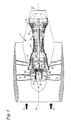
- the best mode for carrying out the invention is set forth in the context of a high bypass gas turbine aircraft engine shown schematically in Fig. 1.
- the engine includes a powerplant 2, a bladed propulsor or fan 4, and a drive system 6 for conveying rotary motion from the powerplant to the fan.
- the drive system is a geared drive system including a planetary gear train 8 and a torque transfer structure or torque frame 10.
- the power plant includes axial flow compressor 12 and 13 rotating about a longitudinally extending central axis 14 to compress intake air 3 and deliver it to a combustor 16 to be mixed with fuel (not shown) and ignited.
- Axial flow turbine 18 extracts energy from the hot combustion gases and, by means of shaft 21 drives compressor 13.
- turbine 19 drives compressor 12 by means of shaft 20.
- Fan 4 is also driven by turbine 19, however, a planetary gear train 8 and a torque frame 10 are located mechanically intermediate the shaft 20 and the fan 4. The fan imparts a modest acceleration to a large volume of air, thereby producing substantial forward thrust. Any energy not consumed in the turbine to drive the fan and compressor is converted to addition forward thrust in the exhaust nozzle 22.
- a sun gear 24 is rotatably driven by the shaft 20.
- a ring gear 26 is fixed to the engine static structure and remains stationary relative to the rotating sun gear.
- a plurality of planet gears 28 is rotatably mounted in a planet carrier 30 so that each planet gear is in meshing engagement with the sun gear and ring gear.
- the sun gear, planet carrier and ring gear share the common central axis 14 while the planet gears have individual axes of rotation 32.
- the sun gear and planet carrier are rotatable about the central axis while the ring gear is fixed relative thereto.
- the gears are bihelical to ensure smooth meshing and quiet operation, however, the invention is independent of the type of gears used, and simple spur gears are depicted in the Figures to ensure clarity of the disclosure.
- a sun gear assembly 50 includes the forward portion 19 of the shaft 20 and the sun gear 24.
- a stationary ring gear assembly 52 includes the ring gear 26 and a nonrotating support structure 54 which may be the engine case or a mounting arrangement connecting the ring gear to the engine case.
- a planet gear assembly 56 includes the plurality of planet gears 28, a carrier 30 having a forward end plate 31 and a rear end plate 33, and planet gear journals 58 mounted in the carrier for rotatably supporting the planet gears.
- the carrier 30 also includes a plurality of apertures, one of which is shown at 76, circumferentially intermediate the planet gears 28.
- the sun gear assembly 50 is an input gear assembly since it is the component of the planetary gear train that receives rotary motion and torque from the powerplant 2 (Fig. 1).
- the planet gear assembly 56 is an output gear assembly since it is the component of the planetary gear train that transmits rotary motion and torque out of the planetary gear train to the fan.
- the torque frame 10 completes the connection from the planet carrier 30 to the bladed propulsor represented by fan blades 4 mounted in the periphery of a disk 70 whose bore 72 is adapted, as by a spline 71, to mate with the torque frame and rotate therewith.
- the torque frame has a circumferentially discontinuous first end 9, terminating in a series of discrete and therefore independently flexible arms 78, and a second end 11 spaced axially from the first end.
- Each arm has a proximal end 29 integral with the torque frame and a distal end 34.
- Each arm projects through a corresponding aperture 76 in the forward end plate 31.
- a joint 79 connects the carrier to the distal ends of the torque frame arms 78.
- the longitudinal centerline 35 of each arm is at a radius at least as great as that of the planet gear axes 32. Consequently, at least a portion of the distal end of each arm is at a radius greater than that of the planet gear axes.
- the torque frame 10 is connected to the rotating disk 70.
- Fig. 3 illustrates a geared drive system of conventional construction.
- the geared drive system includes a ring gear 26', a sun gear 24', planet gears 28', a planet carrier 30', and a torque frame 10'.
- the planet carrier 30' has a forward end plate 31' and a rear end plate 33'.
- Each planet gear is rotatably supported in the carrier by a journal 58', and each journal has a central axis 32' which is the axis of rotation of the associated planet gear.
- only one journal is shown and other structure connecting forward and rear end plates 31' and 33' has been omitted.
- the fan blades are not shown; instead they are represented by the torque T that they impose on the drive system.
- the powerplant rotates the sun gear, planet carrier, and torque frame in direction R, opposite to the direction of the torque load T.
- the torque frame is secured to the planet carrier so that the carrier experiences at least some of the torsional deflection occurring between the powerplant and the load.
- the torque frame is shown as a simple shaft secured to one end plate of the planet carrier. Many other constructions are possible including those in which the torque frame is integral with and indistinguishable from the carrier, however, they all share the characteristic that they transfer torsional deflection into the planet carrier. Consequently, the forward end plate 31' and rear end plate 33' of the planet carrier are circumferentially displaced relative to each other through an angle ⁇ .
- Each journal 58' is similarly deflected as shown in phantom so that the planet gear rotational axis 32' assumes a deflected orientation 32". Since the sun gear and ring gear axes remain parallel to the central axis 14' while the planet gear axes have become skewed or nonparallel relative thereto, the mesh between the planet gears and the sun gear, and the mesh between the planet gears and the ring gear deviate from the mesh that would have occurred had the axes remained parallel. If allowances are made in the gear tooth design to accommodate the effects of nonparallelism, they will only be completely effective at a single operating condition. Reinforcing the planetary gear train as by stiffening the carrier to minimize torsional deflection or by strengthening the gear teeth generally involves increased weight, cost, or physical size, all of which may be unacceptable.
- the present invention isolates the planet carrier from the effects of torsional deflection by transferring torque from the carrier to the torque frame such that substantially all of the torsional deflection is experienced in the torque frame, and substantially none of the torsional deflection occurs in the planet carrier.
- Fig. 4 shows the forward end plate 31 and rear end plate 33 of the carrier 30 abuttingly mated together by carrier assembly bolts 90 (only two of which are shown). As best seen in Fig.'s 6 and 7, the abutting contact extends over a substantial portion of the circumference of the carrier.
- the mating surfaces of the carrier end plates define shoulders 93, and the forward end plate 31 of the carrier includes a series of apertures 76 circumferentially intermediate the sun gears.
- the torque frame 10 is circumferentially discontinuous, terminating in a series of discrete arms 78. Each arm extends axially through the apertures to a location axially intermediate the forward end plate 31 and rear end plate 33 of the carrier where each arm is connected to the carrier by a joint 79 mechanically intermediate the torque frame and the carrier.
- Joint 79 is a spherical bearing 80 comprising a housing 82 with a flange 83 and a truncated spherical ball 84 trapped within the housing, but capable of pivotable motion about both a radial axis 86 perpendicular to the plane of the illustration and a tangential axis 88.
- a housing attachment nut 92 threads onto the end of the housing opposite the flange 83 to clamp the housing 82 onto the shoulder 93 to secure the spherical bearing to the carrier.
- An attachment bolt 96 extends through a substantially axial first hole 98 in each torque frame arm and a second hole 99 in the ball. The attachment bolts 96 and mating nuts 94 effect the connection of each torque frame arm 78 to the articulating balls 84 and hence to the carrier 30.
- the torsional deflection or twisting of the torque frame is manifested as bending of the torque frame arms 78 from their undeflected position through an angle ⁇ ' to their deflected position 78" shown in phantom.
- the pivotability of the ball 84 about the radial axis 86 and the bending of the torque frame arms isolate the carrier 30 from torsional deflections.
- FIG. 5 shows one such connection where each torque frame arm 78 includes a radially extending hole 100 fitted with a pressed-in bushing 102.
- the carrier 30 includes corresponding holes 101, also fitted with bushings 103.
- a trunnion 104 radially disposed in the holes 101 in the carrier 30 and retained therein by a trunnion retention screw 105, extends through the hole 100 in the torque frame arms 78 to pivotably join the carrier and the torque frame.
- the torque frame arm 78 and the bushing 102 pivot about radial axis 86 while the trunnion remains stationary relative to the carrier.
- the trunnion connection accommodates bending of the torque frame arms in the tangential direction without imposing any twist or torsional deflection on the carrier.
- Fig. 6 illustrates, in simplified form, a planet carrier 30 rotating in direction R about the central axis 14.
- a distributed driving force 110 symmetrical about the axial midpoint 112 of the planet gears 28, represents the force conveyed to the carrier by the planet gear orbital motion.
- the distributed driving force which urges rotation of the carrier and, therefore, of the output gear assembly, can be represented by a resultant driving force 114 acting on the carrier at a location corresponding to the axial midpoint 112 of the planet gears.
- the carrier also experiences an individual reaction force 118 at each location 116 corresponding to the axial and circumferential position of each pivotable joint (not shown).
- the pivotable joints are axially positioned at locations 116 so that their individual reaction forces 118 all lie on a common plane perpendicular to the central axis 14 and located at the axial midpoint 112 of the planet gears. Consequently, the net resultant reaction force 120 corresponding to the individual reaction forces 118 also acts at the axial midpoint 112.
- the axial coincidence of the resultant reaction force 120 and the resultant driving force 114 at the axial midpoint 112 ensures that the carrier does not experience torsional deflection.
- the carrier will be subject to a twisting influence tending to diminish the benefits of the spherical bearing.
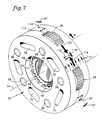
- Fig. 7 illustrates staggering of the joint positions 116 forward and rearward of the midpoint 112.
- the distributed driving force 110 symmetrical about the axial midpoint 112 of the planet gears, urges rotation of the carrier and, therefore, of the output gear assembly.
- the distributed driving force can be represented by a resultant driving force 114 acting on the carrier at a location corresponding to the axial midpoint 112 of the planet gears.
- Circumferentially neighboring joints (not shown) are positioned at locations 116', forwardly offset from the midpoint 112 by a distance d and 116" rearwardly offset from the midpoint by an equal distance d.
- the corresponding individual reaction forces 118' and 118" yield a resultant reaction force 120 acting at the midpoint 112 and axially coincident with the resultant driving force 114.
- the axial coincidence of the resultant reaction force 120 and the resultant driving force 114 at the axial midpoint 112 isolates the carrier from torsional deflection.
- the sun gear assembly 50 (Fig. 2) is the input gear assembly
- the planet gear assembly 56 is the output gear assembly
- the ring gear assembly is stationary.
- any one of these three gear assemblies can be the input, either of the remaining two gear assemblies can be the output and the remaining gear assembly can be stationary.
- the planet carrier is stationary and the ring gear rotates.
- the sun gear assembly is the input gear assembly
- the ring gear assembly rather than the planet gear assembly, is the output gear assembly.
- This gear arrangement requires the ring gear support structure 54 to be rotatable about the central axis 14, and the planet carrier 30 to be stationary.
- the torque frame connects the planet carrier, by way of pivotable joints as described hereinabove, to a stationary component, for example, the nonrotating support structure of a gas turbine engine, for reacting the torque being conveyed through the gear train.
- the distributed driving force 110 and its resultant 114 are still present but do not cause rotary motion of the carrier.
- Geared drive systems can also be arranged so that one of the sun gear assembly, ring gear assembly, and planet gear assembly is an input gear assembly but that both of the remaining gear assemblies are output gear assemblies.
- This single input, dual output arrangement also benefits from the present invention provided the planet carrier is connected to the torque frame proximate its first end with pivotable joints as described hereinabove.
Abstract
Description
- This invention relates generally to torque transmission systems and more particularly to a geared drive system for powering a bladed propulsor.
- Torque is often transmitted through rotating machines from a source of torque to an output device or component. One example is a bladed propulsion system for powering aircraft. In such systems, a powerplant is the source of torque and rotary motion. A drive system conveys the torque and rotary motion to propulsor blades which may be a propeller or fan of a reciprocating engine or gas turbine engine. Frequently, it is desirable or necessary for the rotational speed of the propulsor blades to be different, generally slower, than that of the power plant.
- One way to drive the fan at a rotational speed slower than that of the power plant is to employ a geared drive system which includes a planetary gear train as a member of the drive system. Planetary gear trains are well known and include three gear assemblies--a sun gear assembly including a sun gear, a ring gear assembly including a ring gear, and a planet gear assembly including a planet carrier supporting a plurality of planet gears disposed mechanically intermediate of and in meshing engagement with the ring gear and the sun gear. The sun gear, ring gear and planet carrier share a common longitudinally extending central axis about which at least two of them rotate. The planet gears each have an individual axis of rotation. Typically, the sun gear, ring gear, planet carrier and planet gear axes are all parallel.
- Planetary gear trains are highly versatile. In certain planetary gear trains characterized by a single input and a single output, any one of the aforementioned three gear assemblies can be connected to a rotary input. Either of the other two of the three gear assemblies can serve as an output by being connected to a load to be driven while the remaining gear assembly is held stationary relative to the other two.
- A planetary gear train arrangement that accomplishes a speed reduction is one whose sun gear assembly is driven by the power plant and whose ring gear assembly is stationary. The planet gears each rotate about their individual axes while simultaneously orbiting about the sun gear. The planet gear orbital motion rotates the carrier about the common central axis. The carrier rotary motion is conveyed to the load, in this case the propulsor blades, by an output shaft or other suitable mechanical structure.
- A shortcoming of drive systems that include planetary gear trains arises from the torsional deflection that the drive system will necessarily experience under load due to the elasticity of the materials from which the drive system is made. Some of the torsional deflection occurs in the planet carrier. That is, under an operational load, the carrier structure twists about its central axis so that portions of the carrier which are axially spaced from one another are circumferentially displaced relative to each other. When this occurs, the parallelism of the planet gear axes relative to the sun gear and ring gear axes is disturbed.
- Such disturbance of the gear axis parallelism is undesirable. Gear tooth geometry is often predicated on parallelism between the sun gear, ring gear and planet gear axes. When the parallelism is disturbed under operational load, the tooth mesh deviates from the optimum, resulting in maldistribution of loads along the gear teeth, unequal sharing of the loads between the plurality of planet gears, accelerated gear tooth wear, increased likelihood of gear tooth breakage and increased noise.
- Carrier torsional deflection can also cause wear in the bearing system that supports the planet gears in the carrier. For example, the planets may be supported in the carrier by cylindrical journals that extend through a bore at the center of each planet gear and are securely attached to the carrier. A thin, essentially cylindrical film of lubricant separates the outer periphery of each journal from the bearing surface at the bore of each planet gear. The axis of each journal and the axis of its associated planet gear must remain substantially parallel so that the lubricant film can maintain separation between the gear bore and the journal along the entire axial length of the bearing surface. When the carrier undergoes torsional deflection, each journal is correspondingly deflected along its length, and in particular, its axis becomes skewed or nonparallel relative to the central axis of the gear train. The ability of the planet gear axes to experience a like displacement, thereby remaining parallel to the journal axes, will be at least partially counteracted by the meshing of the planet gears with the ring gear and sun gear. Consequently, the axes of the journals and the axes of the associated planet gears tend to become nonparallel, compromising the lubricant film's ability to separate the journals from the bearing surfaces at the bore of each gear.
- The aforementioned problems might be mitigated by designing the gear teeth to be compatible with a predicted amount of nonparallelism, but this approach is completely effective only at a single operating condition. Attempting to accommodate the shortcomings by strengthening the affected components to tolerate the added wear and stress adds weight and physical size and, therefore, is unacceptable in some applications. Furthermore, the inadequacies of conventional geared drive systems are magnified with increasing power transmission requirements.
- In view of these problems and the unacceptability of conventional solutions in certain environments, a high capacity, compact, reliable, light weight geared drive system that isolates the gears from the adverse effects of carrier torsional deflection is sought.
- In accordance with the present invention the shortcomings of prior art geared drive systems using planetary gear trains are significantly reduced by pivotable joints which connect the planet carrier to one end of a torque transfer structure or torque frame. The other end of the torque frame is connected to either a rotating load or to a nonrotating support structure. The joint arrangement between the planet carrier and the torque frame isolates the carrier from torsional deflections.
- In board terms, the invention provides a geared drive system for a bladed propulsor as claimed in
claim 1. - In an exemplary embodiment, the sun gear assembly of a planetary gear train receives torque and rotary motion from a source thereof such as the power plant of an aircraft gas turbine engine. The ring gear assembly remains stationary and the planet carrier, which is part of a planet gear assembly, is rotatably driven about a central axis by the orbital motion of a plurality of planet gears in a well known manner. A torque transfer structure or torque frame forms at least part of the mechanical path between the planet carrier and the load being driven.
- The torque frame is circumferentially discontinuous at a first end thereby defining a plurality of axially extending arms. A plurality of joints, circumferentially disposed with respect to the carrier and each pivotable about a radial axis, connects at least some of the torque frame arms to the carrier. Under operational load, each joint exerts an individual reaction force on the carrier. Preferably, the joints are positioned so that the resultant reaction force associated with these individual reaction forces is axially coincident with the resultant driving force that rotates the carrier. The torque frame also has a second end near which a connection is made to a rotating component, which in the exemplary embodiment is part of a rotating structure for conveying torque and rotary motion to a fan. In an alternative arrangement, the second end of the torque frame is connected to a mechanical ground that prevents rotation of the torque frame and, therefore, of the carrier.
- Rotary motion of the bladed propulsor is resisted by aerodynamic forces acting at finite distances from a central axis thereby creating a torque load which torsionally deflects the torque frame. The torsional deflection manifests itself as bending of the arms at the first end of the torque frame. The pivotability of the joints connecting the torque frame arms to the carrier prevents the bending of the arms from transmitting any torsional deflection into the carrier. Instead, the carrier experiences only essentially tangentially directed reaction forces at each joint location. By locating the joints so that their resultant reaction force is axially coincident with the resultant force that rotates the carrier, the carrier is also isolated from the twisting effect that would result if the driving force and reaction force were axially separated.
- In an alternative arrangement and operational mode of the planetary gear train, the planet carrier is held stationary and the ring gear assembly is connected to a load to be driven. In this mode, as in all other alternative modes, the same pivotable joint configuration connects the carrier to the torque frame near its first end. The second end of the torque frame is connected to a nonrotating support structure suitable for precluding rotary motion of the carrier; the carrier reacts the torque being conveyed through the rotating components of the gear train rather than participating in the conveyance.
- In other possible arrangements and operational modes, none of the gear assemblies is stationary. One of the assemblies is adapted to accept a rotary input while both of the remaining assemblies are rotary outputs. Use of the pivotable joint as described herein for connecting the planet carrier to the torque frame benefits these single input, dual output configurations as well.
- In one embodiment, the pivotable joint is a spherical bearing allowing pivotable motion about a radial axis. In another embodiment, the joint is a radially oriented trunnion connecting the torque frame to the planet carrier. Other pivotable connections would be equally suitable.
- The efficacy of the invention is independent of other details of the planetary gear train such as the type of gears and the type of bearing arrangement used to support the planet gears in the carrier.
- Some preferred embodiments of the present invention will now be described, by way of example only, with reference to the accompanying drawings in which :
- Fig. 1 is a schematic cross-sectional elevation of a high bypass aircraft engine employing a geared drive system of the present invention;
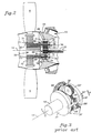
- Fig. 2 is an enlarged cross-sectional elevation of the geared drive system employed in Fig. 1;
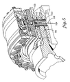
- Fig. 3 is a simplified schematic perspective view of a prior art geared drive system with selected elements removed for clarity;
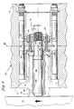
- Fig. 4 is a fragmentary cross-sectional elevation of one embodiment of a joint employed in a geared drive system of the present invention;
- Fig. 5 is a partially sectioned perspective view of an alternative embodiment of a joint employed in a geared drive system of the present invention;
- Fig. 6 is a simplified perspective view of a planet carrier of a geared drive system of the present invention showing various forces acting on the carrier; and
- Fig. 7 is a view similar to Fig. 6 but showing a different force arrangement that preserves the benefits of the present invention.
- The best mode for carrying out the invention is set forth in the context of a high bypass gas turbine aircraft engine shown schematically in Fig. 1. The engine includes a
powerplant 2, a bladed propulsor orfan 4, and adrive system 6 for conveying rotary motion from the powerplant to the fan. In this exemplary embodiment, the drive system is a geared drive system including aplanetary gear train 8 and a torque transfer structure ortorque frame 10. - The power plant includes
axial flow compressor central axis 14 to compressintake air 3 and deliver it to acombustor 16 to be mixed with fuel (not shown) and ignited.Axial flow turbine 18 extracts energy from the hot combustion gases and, by means of shaft 21 drivescompressor 13. Similarly,turbine 19 drivescompressor 12 by means ofshaft 20.Fan 4 is also driven byturbine 19, however, aplanetary gear train 8 and atorque frame 10 are located mechanically intermediate theshaft 20 and thefan 4. The fan imparts a modest acceleration to a large volume of air, thereby producing substantial forward thrust. Any energy not consumed in the turbine to drive the fan and compressor is converted to addition forward thrust in theexhaust nozzle 22. - Referring to Figs. 1 and 2, in the
planetary gear train 8, asun gear 24 is rotatably driven by theshaft 20. Aring gear 26 is fixed to the engine static structure and remains stationary relative to the rotating sun gear. A plurality of planet gears 28 is rotatably mounted in aplanet carrier 30 so that each planet gear is in meshing engagement with the sun gear and ring gear. The sun gear, planet carrier and ring gear share the commoncentral axis 14 while the planet gears have individual axes ofrotation 32. In the illustrated embodiment, the sun gear and planet carrier are rotatable about the central axis while the ring gear is fixed relative thereto. Preferably, the gears are bihelical to ensure smooth meshing and quiet operation, however, the invention is independent of the type of gears used, and simple spur gears are depicted in the Figures to ensure clarity of the disclosure. - The geared drive system of Fig. 1 is illustrated in more detail in Fig. 2. A
sun gear assembly 50 includes theforward portion 19 of theshaft 20 and thesun gear 24. A stationaryring gear assembly 52 includes thering gear 26 and anonrotating support structure 54 which may be the engine case or a mounting arrangement connecting the ring gear to the engine case. Aplanet gear assembly 56 includes the plurality of planet gears 28, acarrier 30 having aforward end plate 31 and arear end plate 33, andplanet gear journals 58 mounted in the carrier for rotatably supporting the planet gears. Thecarrier 30 also includes a plurality of apertures, one of which is shown at 76, circumferentially intermediate the planet gears 28. - The
sun gear assembly 50 is an input gear assembly since it is the component of the planetary gear train that receives rotary motion and torque from the powerplant 2 (Fig. 1). Theplanet gear assembly 56 is an output gear assembly since it is the component of the planetary gear train that transmits rotary motion and torque out of the planetary gear train to the fan. - The
torque frame 10 completes the connection from theplanet carrier 30 to the bladed propulsor represented byfan blades 4 mounted in the periphery of adisk 70 whose bore 72 is adapted, as by aspline 71, to mate with the torque frame and rotate therewith. The torque frame has a circumferentially discontinuousfirst end 9, terminating in a series of discrete and therefore independentlyflexible arms 78, and asecond end 11 spaced axially from the first end. Each arm has aproximal end 29 integral with the torque frame and adistal end 34. Each arm projects through a correspondingaperture 76 in theforward end plate 31. At each of a plurality of locations circumferentially intermediate the planet gears, a joint 79 connects the carrier to the distal ends of thetorque frame arms 78. At the distal end of each arm, thelongitudinal centerline 35 of each arm is at a radius at least as great as that of the planet gear axes 32. Consequently, at least a portion of the distal end of each arm is at a radius greater than that of the planet gear axes. Near its second end, thetorque frame 10 is connected to therotating disk 70. - During operation, rotary motion of the
fan blades 4 is resisted by forces generated when the fan blades interact with the ambient air. Because these resistive forces act at a finite distance from thecentral axis 14, their cumulative effect is to create a torque that must be overcome by the power plant. The joint configuration by which torque is communicated through the planet gear assembly to the torque frame is the central feature of the present invention and is best appreciated in contrast to the conventional arrangement depicted in Fig. 3. - Fig. 3 illustrates a geared drive system of conventional construction. As with the present invention, the geared drive system includes a ring gear 26', a sun gear 24', planet gears 28', a planet carrier 30', and a
torque frame 10'. The planet carrier 30' has a forward end plate 31' and a rear end plate 33'. Each planet gear is rotatably supported in the carrier by a journal 58', and each journal has a central axis 32' which is the axis of rotation of the associated planet gear. For clarity, only one journal is shown and other structure connecting forward and rear end plates 31' and 33' has been omitted. Similarly, the fan blades are not shown; instead they are represented by the torque T that they impose on the drive system. The powerplant rotates the sun gear, planet carrier, and torque frame in direction R, opposite to the direction of the torque load T. Typical of the prior art, the torque frame is secured to the planet carrier so that the carrier experiences at least some of the torsional deflection occurring between the powerplant and the load. The torque frame is shown as a simple shaft secured to one end plate of the planet carrier. Many other constructions are possible including those in which the torque frame is integral with and indistinguishable from the carrier, however, they all share the characteristic that they transfer torsional deflection into the planet carrier. Consequently, the forward end plate 31' and rear end plate 33' of the planet carrier are circumferentially displaced relative to each other through an angle θ. Each journal 58' is similarly deflected as shown in phantom so that the planet gear rotational axis 32' assumes a deflectedorientation 32". Since the sun gear and ring gear axes remain parallel to the central axis 14' while the planet gear axes have become skewed or nonparallel relative thereto, the mesh between the planet gears and the sun gear, and the mesh between the planet gears and the ring gear deviate from the mesh that would have occurred had the axes remained parallel. If allowances are made in the gear tooth design to accommodate the effects of nonparallelism, they will only be completely effective at a single operating condition. Reinforcing the planetary gear train as by stiffening the carrier to minimize torsional deflection or by strengthening the gear teeth generally involves increased weight, cost, or physical size, all of which may be unacceptable. - The present invention isolates the planet carrier from the effects of torsional deflection by transferring torque from the carrier to the torque frame such that substantially all of the torsional deflection is experienced in the torque frame, and substantially none of the torsional deflection occurs in the planet carrier. One embodiment of the unique interface responsible for this isolation is illustrated in Fig. 4 which shows the
forward end plate 31 andrear end plate 33 of thecarrier 30 abuttingly mated together by carrier assembly bolts 90 (only two of which are shown). As best seen in Fig.'s 6 and 7, the abutting contact extends over a substantial portion of the circumference of the carrier. The mating surfaces of the carrier end plates defineshoulders 93, and theforward end plate 31 of the carrier includes a series ofapertures 76 circumferentially intermediate the sun gears. At corresponding circumferential locations, thetorque frame 10 is circumferentially discontinuous, terminating in a series ofdiscrete arms 78. Each arm extends axially through the apertures to a location axially intermediate theforward end plate 31 andrear end plate 33 of the carrier where each arm is connected to the carrier by a joint 79 mechanically intermediate the torque frame and the carrier. Joint 79 is aspherical bearing 80 comprising ahousing 82 with aflange 83 and a truncatedspherical ball 84 trapped within the housing, but capable of pivotable motion about both aradial axis 86 perpendicular to the plane of the illustration and atangential axis 88. Ahousing attachment nut 92 threads onto the end of the housing opposite theflange 83 to clamp thehousing 82 onto theshoulder 93 to secure the spherical bearing to the carrier. Anattachment bolt 96 extends through a substantially axialfirst hole 98 in each torque frame arm and asecond hole 99 in the ball. Theattachment bolts 96 andmating nuts 94 effect the connection of eachtorque frame arm 78 to the articulatingballs 84 and hence to thecarrier 30. - Under torsional load, the torsional deflection or twisting of the torque frame is manifested as bending of the
torque frame arms 78 from their undeflected position through an angle θ' to their deflectedposition 78" shown in phantom. The pivotability of theball 84 about theradial axis 86 and the bending of the torque frame arms isolate thecarrier 30 from torsional deflections. - Alternative pivotable connections between the carrier and the torque frame are equally suitable. Fig. 5 shows one such connection where each
torque frame arm 78 includes aradially extending hole 100 fitted with a pressed-inbushing 102. Thecarrier 30 includes correspondingholes 101, also fitted withbushings 103. Atrunnion 104, radially disposed in theholes 101 in thecarrier 30 and retained therein by atrunnion retention screw 105, extends through thehole 100 in thetorque frame arms 78 to pivotably join the carrier and the torque frame. Under operational load, thetorque frame arm 78 and thebushing 102 pivot aboutradial axis 86 while the trunnion remains stationary relative to the carrier. As in the case of the ball joint 80 of Fig. 4, the trunnion connection accommodates bending of the torque frame arms in the tangential direction without imposing any twist or torsional deflection on the carrier. - The axial positioning of the pivotable joint also contributes to the performance of the drive system of the present invention. Fig. 6 illustrates, in simplified form, a
planet carrier 30 rotating in direction R about thecentral axis 14. A distributed drivingforce 110, symmetrical about theaxial midpoint 112 of the planet gears 28, represents the force conveyed to the carrier by the planet gear orbital motion. The distributed driving force, which urges rotation of the carrier and, therefore, of the output gear assembly, can be represented by aresultant driving force 114 acting on the carrier at a location corresponding to theaxial midpoint 112 of the planet gears. The carrier also experiences anindividual reaction force 118 at eachlocation 116 corresponding to the axial and circumferential position of each pivotable joint (not shown). The pivotable joints are axially positioned atlocations 116 so that theirindividual reaction forces 118 all lie on a common plane perpendicular to thecentral axis 14 and located at theaxial midpoint 112 of the planet gears. Consequently, the netresultant reaction force 120 corresponding to theindividual reaction forces 118 also acts at theaxial midpoint 112. The axial coincidence of theresultant reaction force 120 and theresultant driving force 114 at theaxial midpoint 112 ensures that the carrier does not experience torsional deflection. If the axial coincidence were absent, for example, if the joints are placed so that their resultant reaction force 120' is axially separated by a distance S from theresultant driving force 114, the carrier will be subject to a twisting influence tending to diminish the benefits of the spherical bearing. - Fig. 7 illustrates staggering of the
joint positions 116 forward and rearward of themidpoint 112. The distributed drivingforce 110, symmetrical about theaxial midpoint 112 of the planet gears, urges rotation of the carrier and, therefore, of the output gear assembly. The distributed driving force can be represented by aresultant driving force 114 acting on the carrier at a location corresponding to theaxial midpoint 112 of the planet gears. Circumferentially neighboring joints (not shown) are positioned at locations 116', forwardly offset from themidpoint 112 by a distance d and 116" rearwardly offset from the midpoint by an equal distance d. Because of the circumferentially alternating positioning of the joints at equal distances forward and rearward of themidpoint 112, the correspondingindividual reaction forces 118' and 118" yield aresultant reaction force 120 acting at themidpoint 112 and axially coincident with theresultant driving force 114. The axial coincidence of theresultant reaction force 120 and theresultant driving force 114 at theaxial midpoint 112 isolates the carrier from torsional deflection. - In the foregoing disclosure of the best mode for carrying out the invention, the sun gear assembly 50 (Fig. 2) is the input gear assembly, the
planet gear assembly 56 is the output gear assembly, and the ring gear assembly is stationary. Those skilled in the art will appreciate that any one of these three gear assemblies can be the input, either of the remaining two gear assemblies can be the output and the remaining gear assembly can be stationary. For example, in one arrangement the planet carrier is stationary and the ring gear rotates. In this arrangement, the sun gear assembly is the input gear assembly, but the ring gear assembly, rather than the planet gear assembly, is the output gear assembly. This gear arrangement requires the ringgear support structure 54 to be rotatable about thecentral axis 14, and theplanet carrier 30 to be stationary. In this arrangement, the torque frame connects the planet carrier, by way of pivotable joints as described hereinabove, to a stationary component, for example, the nonrotating support structure of a gas turbine engine, for reacting the torque being conveyed through the gear train. The distributed drivingforce 110 and its resultant 114 are still present but do not cause rotary motion of the carrier. - Geared drive systems can also be arranged so that one of the sun gear assembly, ring gear assembly, and planet gear assembly is an input gear assembly but that both of the remaining gear assemblies are output gear assemblies. This single input, dual output arrangement also benefits from the present invention provided the planet carrier is connected to the torque frame proximate its first end with pivotable joints as described hereinabove.
- The best mode for carrying out the invention uses bihelical gears and a journal bearing arrangement to support the planet in the carrier. However, other gear types and bearing arrangements can be used without departing from the spirit and scope of the present invention.
- Although this invention was described in the context of geared axial flow gas turbine engines, it is applicable to other machines that transmit torque through a planetary gear train.
Claims (12)
- A geared drive system for a bladed propulsor, comprising:
a planetary gear train (8) including:a sun gear assembly (50) comprising a sun gear (24),a ring gear assembly (52) comprising a ring gear (26),a planet gear assembly (56) comprising a plurality of planet gears (28) mounted in a planet carrier (30) and disposed mechanically intermediate of and in meshing engagement with the sun gear (24) and the ring gear (26), the planet carrier (30) having a forward end plate (31) and a rear end plate (33) abuttingly mated to each other, the abutting contact between the plates extending over a substantial portion of the circumference of the carrier, the forward end plate (31) also having a plurality of apertures (76),wherein one of the sun gear assembly (50), ring gear assembly (52), and planet gear assembly (56) is an input gear assembly receiving torque from a source thereof and at least one of the remaining of the sun gear assembly (50), ring gear assembly (52) and planet gear assembly (56) is an output gear assembly for delivering the torque to a load; anda torque transfer structure (10) having a first end (9) terminating in a series of discrete, independently flexible arms (78), each arm having a proximal end (29) and a distal end (34), each arm (78) projecting axially through a corresponding end plate aperture (76), the distal ends (34) of the arms (78) being joined to the planet gear assembly (56) by a plurality of joints (79), at least a portion of the distal end (34) of each arm being at a radius greater than that of the planet gear axes (32), each of said joints (79) being, with respect to a load path through the gear train, mechanically intermediate the torque transfer structure (10) and the planet gear assembly (56) wherein each joint (79) is pivotable about at least a radial axis (86). - The geared drive system of claim 1 wherein the pivotable joints (79) are located with respect to the planet carrier (30) such that a resultant driving force acting on the planet carrier (30) and a resultant reaction force exerted by the pivotable joints (79) on the carrier (30) are axially coincident.
- The geared drive system of claim 1 or 2 wherein the sun gear assembly (50) is the input gear assembly, the planet gear assembly (56) is the output gear assembly and the ring gear assembly (52) is stationary with respect to the sun gear assembly (50) and the planet gear assembly (56).
- The geared drive system of claim 1 or 2 wherein the sun gear assembly (50) is the input gear assembly, the ring gear assembly (52) is the output gear assembly and the planet carrier (30) is stationary with respect to the sun gear assembly (50) and the ring gear assembly (52).
- The geared drive system of claim 1 or 2 wherein the sun gear assembly (50) is the input gear assembly, and the ring gear assembly (52) and planet gear assembly (56) are the output gear assemblies.
- The geared drive system of any of claims 1 to 5 wherein the joints (79) comprise spherical bearings (80).
- The geared drive system of claim 6 wherein:a first end of the torque transfer structure (10) terminates in a plurality of arms (78) each having a substantially axial first hole (98) therethrough, andeach spherical bearing (80) comprises:a housing (82) secured to the planet carrier (30) and stationary with respect thereto,a ball (84) disposed within the housing (82) and capable of pivotable motion with respect thereto about at least the radial axis (86), each ball also being connected to a corresponding one of the plurality of arms (78).
- The geared drive system of any of claims 1 to 5 wherein:the first end of the torque transfer structure (10) terminates in a plurality of arms (78) each having a radially extending hole (100) therethrough,the carrier (30) includes a plurality of corresponding radially extending holes (101), anda trunnion (104) is radially disposed through each radially extending hole (100) and through each corresponding hole (101) to pivotably join the torque frame (10) to the carrier (30).
- The geared drive system of any preceding claim wherein the sun gear (24), the ring gear (52), and the plurality of planet gears (28) are bihelical.
- A geared drive system for a bladed propulsor, comprising:
a planetary gear train including:a sun gear assembly (50) comprising a sun gear (24) driven by a source of input torque,a ring gear assembly (52) comprising a ring gear (26) stationary with respect to the sun gear assembly (50),a planet gear assembly (56) including a plurality of planet gears (28) supported in a planet carrier (30) by journals and disposed mechanically intermediate of and in meshing engagement with the sun gear (24) and the ring gear (26) whereby the planet carrier (30) is urged to rotate by a resultant driving force, the planet carrier (30) having a forward end plate (31) and a rear end plate (33) abuttingly mated to each other, the abutting contact between the plates extending over a substantial portion of the circumference of the carrier (30), the forward end plate (31) also having a plurality of apertures (76);a torque transfer structure (10) for driving a load, the torque transfer structure (10) being rotatable about a central axis (14) and having a first end (9) terminating in a series of discrete, independently flexible arms (78), each arm having a proximal end (29) and a distal end (34), each arm projecting axially through a corresponding end plate aperture (76), at least a portion of the distal end (34) of each arm (78) being at a radius greater than that of the planet gear axes (32), the torque transfer structure also having a second end (11) connected to a rotating component (4); anda plurality of joints (79) circumferentially disposed with respect to the carrier (30), each of said joints (79) being, with respect to a load path through the gear train, mechanically intermediate the torque transfer structure (10) and the planet gear assembly (56) and each joint (79) being pivotable about at least a radial axis (86) for joining the planet carrier (30) to the distal ends (34) of the arms (78), each joint (79) exerting a resultant reaction force on the carrier (30) and wherein the joints (79) are axially positioned with respect to the carrier (30) such that the resultant reaction force is axially coincident with the resultant driving force at the axial midpoint of the planet gears (28) or transmitting the resultant driving force from the carrier to the arms without imposing torsional deflection on the carrier (30). - A geared drive system for a bladed propulsor, comprising:
a planetary gear train (8) including:a sun gear assembly (50) comprising a sun gear (24) driven by a source of input torque,a ring gear assembly (52) comprising a ring gear (26) stationary with respect to the sun gear assembly (50),a planet gear assembly (56) comprising a plurality of planet gears (28) supported in a planet carrier (30) by journals and disposed mechanically intermediate of and in meshing engagement with the sun gear (24) and the ring gear (26) whereby the planet carrier (30) is urged to rotate by a resultant driving force, the planet carrier (30) having a forward end plate (31) and a rear end plate (33) abuttingly mated to each other, the abutting contact between the plates (31,33) extending over a substantial portion of the circumference of the carrier (30), the forward end plate (31) also having a plurality of apertures (76);a torque transfer structure (10) for driving a load, the torque transfer structure (10) being rotatable about a central axis (14) and having a first end (9) terminating in a series of discrete, independently flexible arms (78), each arm having a proximal end (29) and a distal end (34), each arm (78) projecting axially through a corresponding end plate aperture (76), at least a portion of the distal end (34) of each arm (78) being at a radius greater than that of the planet gear axes (32), the torque transfer structure (10) also having a second end connected to a rotating component (11); anda plurality of joints (79) circumferentially disposed with respect to the carrier (30), each of said joints (79) being, with respect to a load path through the gear train, mechanically intermediate the torque transfer structure (10) and the planet gear assembly (56) and each joint (79) being pivotable about at least a radial axis (86) for joining the planet carrier (30) to the distal ends (34) of the arms (78), each joint (79) exerting a resultant reaction force on the carrier (30) and wherein the joints (79) are axially positioned with respect to the carrier (30) on a common plane perpendicular to the central axis (14) and at the axial midpoint (112) of the planet gears (28) for transmitting the resultant driving force from the carrier (30) to the arms (78) without imposing torsional deflection on the carrier (30). - A geared drive system as in claim 10 or 11 wherein the sun gear assembly (50) is an input gear assembly for receiving torque from a source thereof the ring gear assembly (52) is an output gear assembly for delivering torque to a load, the planet carrier (30) is stationary, and the second end (11) of the torque transfer structure (10) is connected to a nonrotating structure.
Applications Claiming Priority (3)
| Application Number | Priority Date | Filing Date | Title |
|---|---|---|---|
| US75827 | 1979-09-14 | ||
| US08/075,827 US5466198A (en) | 1993-06-11 | 1993-06-11 | Geared drive system for a bladed propulsor |
| PCT/US1994/006507 WO1994029614A1 (en) | 1993-06-11 | 1994-06-08 | Geared drive system for a bladed propulsor |
Publications (2)
| Publication Number | Publication Date |
|---|---|
| EP0701669A1 EP0701669A1 (en) | 1996-03-20 |
| EP0701669B1 true EP0701669B1 (en) | 1997-01-02 |
Family
ID=22128237
Family Applications (1)
| Application Number | Title | Priority Date | Filing Date |
|---|---|---|---|
| EP94919431A Expired - Lifetime EP0701669B1 (en) | 1993-06-11 | 1994-06-08 | Geared drive system for a bladed propulsor |
Country Status (5)
| Country | Link |
|---|---|
| US (1) | US5466198A (en) |
| EP (1) | EP0701669B1 (en) |
| JP (1) | JP3497509B2 (en) |
| DE (1) | DE69401357T2 (en) |
| WO (1) | WO1994029614A1 (en) |
Families Citing this family (224)
| Publication number | Priority date | Publication date | Assignee | Title |
|---|---|---|---|---|
| DE29609794U1 (en) * | 1996-06-03 | 1996-08-22 | Aerodyn Gmbh | Gear-generator combination |
| FI108959B (en) | 1998-06-18 | 2002-04-30 | Valmet Voimansiirto Oy | Planetary gear for a wind turbine |
| DE19844843B4 (en) * | 1998-09-30 | 2006-02-09 | Mtu Aero Engines Gmbh | planetary gear |
| US6223616B1 (en) * | 1999-12-22 | 2001-05-01 | United Technologies Corporation | Star gear system with lubrication circuit and lubrication method therefor |
| US6663530B2 (en) * | 2001-12-14 | 2003-12-16 | Pratt & Whitney Canada Corp. | Zero twist carrier |
| US6964155B2 (en) * | 2002-12-30 | 2005-11-15 | United Technologies Corporation | Turbofan engine comprising an spicyclic transmission having bearing journals |
| FR2853382B1 (en) * | 2003-04-04 | 2006-04-28 | Hispano Suiza Sa | FLEXIBLE BONDING SYSTEM BETWEEN A SATELLITE HOLDER AND THE FIXED SUPPORT IN A SPEED REDUCER |
| US7104918B2 (en) * | 2003-07-29 | 2006-09-12 | Pratt & Whitney Canada Corp. | Compact epicyclic gear carrier |
| DE10334459A1 (en) * | 2003-07-29 | 2005-03-17 | Zf Friedrichshafen Ag | Guide disc assembly of a planet carrier for a planetary gear |
| WO2006060006A1 (en) | 2004-12-01 | 2006-06-08 | United Technologies Corporation | Tip turbine engine non-metallic tailcone |
| US8468795B2 (en) | 2004-12-01 | 2013-06-25 | United Technologies Corporation | Diffuser aspiration for a tip turbine engine |
| WO2006060014A1 (en) * | 2004-12-01 | 2006-06-08 | United Technologies Corporation | Starter generator system for a tip turbine engine |
| US7976272B2 (en) | 2004-12-01 | 2011-07-12 | United Technologies Corporation | Inflatable bleed valve for a turbine engine |
| DE602004016059D1 (en) | 2004-12-01 | 2008-10-02 | United Technologies Corp | TIP TURBINE ENGINE WITH HEAT EXCHANGER |
| WO2006060004A1 (en) | 2004-12-01 | 2006-06-08 | United Technologies Corporation | Combustor for turbine engine |
| EP1834071B1 (en) * | 2004-12-01 | 2013-03-13 | United Technologies Corporation | Inducer for a fan blade of a tip turbine engine |
| US7878762B2 (en) * | 2004-12-01 | 2011-02-01 | United Technologies Corporation | Tip turbine engine comprising turbine clusters and radial attachment lock arrangement therefor |
| US8757959B2 (en) * | 2004-12-01 | 2014-06-24 | United Technologies Corporation | Tip turbine engine comprising a nonrotable compartment |
| EP1819907A2 (en) * | 2004-12-01 | 2007-08-22 | United Technologies Corporation | Fan blade with integral diffuser section and tip turbine blade section for a tip turbine engine |
| EP1825113B1 (en) * | 2004-12-01 | 2012-10-24 | United Technologies Corporation | Counter-rotating gearbox for tip turbine engine |
| WO2006059977A1 (en) | 2004-12-01 | 2006-06-08 | United Technologies Corporation | Tip turbine engine and corresponding orepating method |
| EP1831519B1 (en) | 2004-12-01 | 2010-08-04 | United Technologies Corporation | Tip turbine engine with multiple fan and turbine stages |
| US8641367B2 (en) | 2004-12-01 | 2014-02-04 | United Technologies Corporation | Plurality of individually controlled inlet guide vanes in a turbofan engine and corresponding controlling method |
| US8087885B2 (en) | 2004-12-01 | 2012-01-03 | United Technologies Corporation | Stacked annular components for turbine engines |
| US8561383B2 (en) * | 2004-12-01 | 2013-10-22 | United Technologies Corporation | Turbine engine with differential gear driven fan and compressor |
| DE602004031470D1 (en) | 2004-12-01 | 2011-03-31 | United Technologies Corp | TRANSITION CHANNEL WITH MEANS FOR FLOW VECTOR INFLUENCE ON A GAS TURBINE |
| EP1841959B1 (en) * | 2004-12-01 | 2012-05-09 | United Technologies Corporation | Balanced turbine rotor fan blade for a tip turbine engine |
| WO2006059979A1 (en) * | 2004-12-01 | 2006-06-08 | United Technologies Corporation | Tip turbine engine integral case, vane, mount, and mixer |
| WO2006059994A1 (en) * | 2004-12-01 | 2006-06-08 | United Technologies Corporation | Seal assembly for a fan-turbine rotor of a tip turbine engine |
| WO2006059989A1 (en) * | 2004-12-01 | 2006-06-08 | United Technologies Corporation | Tip turbine engine support structure |
| DE602004029950D1 (en) * | 2004-12-01 | 2010-12-16 | United Technologies Corp | SLIDED GEAR ASSEMBLY FOR A TOP TURBINE ENGINE |
| WO2006059971A2 (en) * | 2004-12-01 | 2006-06-08 | United Technologies Corporation | Tip turbine engine integral fan, combustor, and turbine case |
| US8061968B2 (en) * | 2004-12-01 | 2011-11-22 | United Technologies Corporation | Counter-rotating compressor case and assembly method for tip turbine engine |
| WO2006059985A1 (en) | 2004-12-01 | 2006-06-08 | United Technologies Corporation | Axial compressor for tip turbine engine |
| WO2006060005A1 (en) * | 2004-12-01 | 2006-06-08 | United Technologies Corporation | Fan-turbine rotor assembly with integral inducer section for a tip turbine engine |
| WO2006059975A1 (en) | 2004-12-01 | 2006-06-08 | United Technologies Corporation | Peripheral combustor for tip turbine engine |
| US9003759B2 (en) | 2004-12-01 | 2015-04-14 | United Technologies Corporation | Particle separator for tip turbine engine |
| US7980054B2 (en) | 2004-12-01 | 2011-07-19 | United Technologies Corporation | Ejector cooling of outer case for tip turbine engine |
| WO2006059981A1 (en) * | 2004-12-01 | 2006-06-08 | United Technologies Corporation | Hydraulic seal for a gearbox of a tip turbine engine |
| WO2006060000A1 (en) | 2004-12-01 | 2006-06-08 | United Technologies Corporation | Variable fan inlet guide vane assembly, turbine engine with such an assembly and corresponding controlling method |
| US7882695B2 (en) | 2004-12-01 | 2011-02-08 | United Technologies Corporation | Turbine blow down starter for turbine engine |
| US7874802B2 (en) * | 2004-12-01 | 2011-01-25 | United Technologies Corporation | Tip turbine engine comprising turbine blade clusters and method of assembly |
| EP1825170B1 (en) * | 2004-12-01 | 2009-03-18 | United Technologies Corporation | Gearbox lubrication supply system for a tip turbine engine |
| EP1825128B1 (en) * | 2004-12-01 | 2011-03-02 | United Technologies Corporation | Regenerative turbine blade and vane cooling for a tip turbine engine |
| WO2006059988A1 (en) * | 2004-12-01 | 2006-06-08 | United Technologies Corporation | Modular tip turbine engine |
| US7883315B2 (en) * | 2004-12-01 | 2011-02-08 | United Technologies Corporation | Seal assembly for a fan rotor of a tip turbine engine |
| US8033094B2 (en) * | 2004-12-01 | 2011-10-11 | United Technologies Corporation | Cantilevered tip turbine engine |
| US8152469B2 (en) * | 2004-12-01 | 2012-04-10 | United Technologies Corporation | Annular turbine ring rotor |
| DE602004031986D1 (en) * | 2004-12-01 | 2011-05-05 | United Technologies Corp | BLOWER TURBINE ROTOR ASSEMBLY FOR A TOP TURBINE ENGINE |
| WO2006059972A1 (en) * | 2004-12-01 | 2006-06-08 | United Technologies Corporation | Compressor variable stage remote actuation for turbine engine |
| US8096753B2 (en) | 2004-12-01 | 2012-01-17 | United Technologies Corporation | Tip turbine engine and operating method with reverse core airflow |
| US9109537B2 (en) * | 2004-12-04 | 2015-08-18 | United Technologies Corporation | Tip turbine single plane mount |
| US8267826B2 (en) | 2005-03-15 | 2012-09-18 | United Technologies Corporation | Uninterruptible oil supply in planetary system |
| US8585538B2 (en) | 2006-07-05 | 2013-11-19 | United Technologies Corporation | Coupling system for a star gear train in a gas turbine engine |
| US8667688B2 (en) | 2006-07-05 | 2014-03-11 | United Technologies Corporation | Method of assembly for gas turbine fan drive gear system |
| US7704178B2 (en) | 2006-07-05 | 2010-04-27 | United Technologies Corporation | Oil baffle for gas turbine fan drive gear system |
| US7926260B2 (en) * | 2006-07-05 | 2011-04-19 | United Technologies Corporation | Flexible shaft for gas turbine engine |
| US9194255B2 (en) | 2006-07-05 | 2015-11-24 | United Technologies Corporation | Oil baffle for gas turbine fan drive gear system |
| US8708863B2 (en) | 2006-08-15 | 2014-04-29 | United Technologies Corporation | Epicyclic gear train |
| US10107231B2 (en) | 2006-08-15 | 2018-10-23 | United Technologies Corporation | Gas turbine engine with geared architecture |
| US8939864B2 (en) | 2006-08-15 | 2015-01-27 | United Technologies Corporation | Gas turbine engine lubrication |
| US20120213628A1 (en) | 2006-08-15 | 2012-08-23 | Mccune Michael E | Gas turbine engine with geared architecture |
| US8858388B2 (en) | 2006-08-15 | 2014-10-14 | United Technologies Corporation | Gas turbine engine gear train |
| US9976437B2 (en) | 2006-08-15 | 2018-05-22 | United Technologies Corporation | Epicyclic gear train |
| US8753243B2 (en) * | 2006-08-15 | 2014-06-17 | United Technologies Corporation | Ring gear mounting arrangement with oil scavenge scheme |
| WO2008045072A1 (en) | 2006-10-12 | 2008-04-17 | United Technologies Corporation | Dual function cascade integrated variable area fan nozzle and thrust reverser |
| US7849668B2 (en) * | 2006-10-25 | 2010-12-14 | United Technologies Corporation | Rotor brake and windmilling lubrication system for geared turbofan engine |
| US20080273961A1 (en) | 2007-03-05 | 2008-11-06 | Rosenkrans William E | Flutter sensing and control system for a gas turbine engine |
| US8967945B2 (en) | 2007-05-22 | 2015-03-03 | United Technologies Corporation | Individual inlet guide vane control for tip turbine engine |
| US11149650B2 (en) | 2007-08-01 | 2021-10-19 | Raytheon Technologies Corporation | Turbine section of high bypass turbofan |
| US11242805B2 (en) | 2007-08-01 | 2022-02-08 | Raytheon Technologies Corporation | Turbine section of high bypass turbofan |
| US20150377123A1 (en) | 2007-08-01 | 2015-12-31 | United Technologies Corporation | Turbine section of high bypass turbofan |
| US11486311B2 (en) | 2007-08-01 | 2022-11-01 | Raytheon Technologies Corporation | Turbine section of high bypass turbofan |
| US11346289B2 (en) | 2007-08-01 | 2022-05-31 | Raytheon Technologies Corporation | Turbine section of high bypass turbofan |
| US9701415B2 (en) | 2007-08-23 | 2017-07-11 | United Technologies Corporation | Gas turbine engine with axial movable fan variable area nozzle |
| US9957918B2 (en) * | 2007-08-28 | 2018-05-01 | United Technologies Corporation | Gas turbine engine front architecture |
| US20140157754A1 (en) | 2007-09-21 | 2014-06-12 | United Technologies Corporation | Gas turbine engine compressor arrangement |
| US10151248B2 (en) | 2007-10-03 | 2018-12-11 | United Technologies Corporation | Dual fan gas turbine engine and gear train |
| US8205432B2 (en) * | 2007-10-03 | 2012-06-26 | United Technologies Corporation | Epicyclic gear train for turbo fan engine |
| WO2009052824A2 (en) * | 2007-10-22 | 2009-04-30 | Vestas Wind Systems A/S | Epicyclic gear stage for a wind turbine gearbox, a wind turbine gearbox and a wind turbine |
| US20100303626A1 (en) * | 2007-12-20 | 2010-12-02 | Vestas Wind Systems A/S | Epicyclic gear stage for a wind turbine gearbox, a wind turbine gearbox and a wind turbine |
| US8348803B2 (en) * | 2008-04-17 | 2013-01-08 | Kawasaki Jukogyo Kabushiki Kaisha | Planetary reduction gear apparatus |
| US20140174056A1 (en) | 2008-06-02 | 2014-06-26 | United Technologies Corporation | Gas turbine engine with low stage count low pressure turbine |
| DE102008063044B4 (en) * | 2008-12-23 | 2012-01-05 | Aerodyn Engineering Gmbh | planetary gear |
| US9885313B2 (en) | 2009-03-17 | 2018-02-06 | United Technologes Corporation | Gas turbine engine bifurcation located fan variable area nozzle |
| CA2682454C (en) | 2009-04-14 | 2013-11-26 | Kawasaki Jukogyo Kabushiki Kaisha | Planetary reduction gear apparatus |
| US8689538B2 (en) | 2009-09-09 | 2014-04-08 | The Boeing Company | Ultra-efficient propulsor with an augmentor fan circumscribing a turbofan |
| JP4975081B2 (en) * | 2009-10-30 | 2012-07-11 | 川崎重工業株式会社 | Planetary gear reducer |
| US8672801B2 (en) * | 2009-11-30 | 2014-03-18 | United Technologies Corporation | Mounting system for a planetary gear train in a gas turbine engine |
| IT1401662B1 (en) | 2010-08-27 | 2013-08-02 | Nuova Pignone S R L | AXIAL MULTISTAGE EXPANDER DEVICE WITH GEARS, SYSTEM AND METHOD. |
| US8813469B2 (en) | 2010-10-12 | 2014-08-26 | United Technologies Corporation | Planetary gear system arrangement with auxiliary oil system |
| US9995174B2 (en) | 2010-10-12 | 2018-06-12 | United Technologies Corporation | Planetary gear system arrangement with auxiliary oil system |
| US10605167B2 (en) | 2011-04-15 | 2020-03-31 | United Technologies Corporation | Gas turbine engine front center body architecture |
| US8900083B2 (en) | 2011-04-27 | 2014-12-02 | United Technologies Corporation | Fan drive gear system integrated carrier and torque frame |
| US8777793B2 (en) * | 2011-04-27 | 2014-07-15 | United Technologies Corporation | Fan drive planetary gear system integrated carrier and torque frame |
| US9239012B2 (en) | 2011-06-08 | 2016-01-19 | United Technologies Corporation | Flexible support structure for a geared architecture gas turbine engine |
| US9523422B2 (en) | 2011-06-08 | 2016-12-20 | United Technologies Corporation | Flexible support structure for a geared architecture gas turbine engine |
| US9631558B2 (en) | 2012-01-03 | 2017-04-25 | United Technologies Corporation | Geared architecture for high speed and small volume fan drive turbine |
| US9506422B2 (en) | 2011-07-05 | 2016-11-29 | United Technologies Corporation | Efficient, low pressure ratio propulsor for gas turbine engines |
| US9909505B2 (en) | 2011-07-05 | 2018-03-06 | United Technologies Corporation | Efficient, low pressure ratio propulsor for gas turbine engines |
| US9938898B2 (en) | 2011-07-29 | 2018-04-10 | United Technologies Corporation | Geared turbofan bearing arrangement |
| ITTO20111007A1 (en) * | 2011-11-03 | 2013-05-04 | Avio Spa | EPICYCLOIDAL ROTISM |
| EP2610461B1 (en) | 2011-12-30 | 2019-10-23 | United Technologies Corporation | Turbine engine |
| US9416677B2 (en) | 2012-01-10 | 2016-08-16 | United Technologies Corporation | Gas turbine engine forward bearing compartment architecture |
| US20130186058A1 (en) | 2012-01-24 | 2013-07-25 | William G. Sheridan | Geared turbomachine fan and compressor rotation |
| US8935913B2 (en) | 2012-01-31 | 2015-01-20 | United Technologies Corporation | Geared turbofan gas turbine engine architecture |
| US10415468B2 (en) | 2012-01-31 | 2019-09-17 | United Technologies Corporation | Gas turbine engine buffer system |
| US20150192070A1 (en) | 2012-01-31 | 2015-07-09 | United Technologies Corporation | Geared turbofan gas turbine engine architecture |
| US9835052B2 (en) | 2012-01-31 | 2017-12-05 | United Technologies Corporation | Gas turbine engine with high speed low pressure turbine section and bearing support features |
| US20130192198A1 (en) | 2012-01-31 | 2013-08-01 | Lisa I. Brilliant | Compressor flowpath |
| US8720306B2 (en) | 2012-01-31 | 2014-05-13 | United Technologies Corporation | Turbine engine gearbox |
| US20130192251A1 (en) | 2012-01-31 | 2013-08-01 | Peter M. Munsell | Buffer system that communicates buffer supply air to one or more portions of a gas turbine engine |
| US20150345426A1 (en) | 2012-01-31 | 2015-12-03 | United Technologies Corporation | Geared turbofan gas turbine engine architecture |
| US9394852B2 (en) | 2012-01-31 | 2016-07-19 | United Technologies Corporation | Variable area fan nozzle with wall thickness distribution |
| US10287914B2 (en) | 2012-01-31 | 2019-05-14 | United Technologies Corporation | Gas turbine engine with high speed low pressure turbine section and bearing support features |
| US20130192191A1 (en) | 2012-01-31 | 2013-08-01 | Frederick M. Schwarz | Gas turbine engine with high speed low pressure turbine section and bearing support features |
| US8869508B2 (en) | 2012-01-31 | 2014-10-28 | United Technologies Corporation | Gas turbine engine variable area fan nozzle control |
| US8863491B2 (en) | 2012-01-31 | 2014-10-21 | United Technologies Corporation | Gas turbine engine shaft bearing configuration |
| US9169781B2 (en) | 2012-01-31 | 2015-10-27 | United Technologies Corporation | Turbine engine gearbox |
| US20130192240A1 (en) | 2012-01-31 | 2013-08-01 | Peter M. Munsell | Buffer system for a gas turbine engine |
| US10113434B2 (en) | 2012-01-31 | 2018-10-30 | United Technologies Corporation | Turbine blade damper seal |
| US10400629B2 (en) | 2012-01-31 | 2019-09-03 | United Technologies Corporation | Gas turbine engine shaft bearing configuration |
| US10724431B2 (en) | 2012-01-31 | 2020-07-28 | Raytheon Technologies Corporation | Buffer system that communicates buffer supply air to one or more portions of a gas turbine engine |
| US10107191B2 (en) | 2012-02-29 | 2018-10-23 | United Technologies Corporation | Geared gas turbine engine with reduced fan noise |
| CN108317238B (en) * | 2012-03-23 | 2021-11-09 | 联合工艺公司 | Planetary gear system arrangement with auxiliary oil system |
| US8961112B2 (en) | 2012-03-26 | 2015-02-24 | United Technologies Corporation | Torque frame bushing arrangement for gas turbine engine fan drive gear system |
| US8790075B2 (en) | 2012-03-30 | 2014-07-29 | United Technologies Corporation | Gas turbine engine geared architecture axial retention arrangement |
| US10125693B2 (en) | 2012-04-02 | 2018-11-13 | United Technologies Corporation | Geared turbofan engine with power density range |
| US10138809B2 (en) | 2012-04-02 | 2018-11-27 | United Technologies Corporation | Geared turbofan engine with a high ratio of thrust to turbine volume |
| US8585536B2 (en) | 2012-04-02 | 2013-11-19 | Hamilton Sundstrand Corporation | Gear carrier frame |
| US20130255275A1 (en) * | 2012-04-02 | 2013-10-03 | Frederick M. Schwarz | Geared turbofan engine with power density range |
| US20130269479A1 (en) * | 2012-04-11 | 2013-10-17 | General Electric Company | Gearbox and support apparatus for gearbox carrier |
| JP5915352B2 (en) * | 2012-04-19 | 2016-05-11 | トヨタ自動車株式会社 | Turboprop / fan type jet engine with transmission |
| US8484942B1 (en) | 2012-05-30 | 2013-07-16 | United Technologies Corporation | Planetary gear system arrangement with auxiliary oil system |
| US20150308351A1 (en) | 2012-05-31 | 2015-10-29 | United Technologies Corporation | Fundamental gear system architecture |
| US8572943B1 (en) | 2012-05-31 | 2013-11-05 | United Technologies Corporation | Fundamental gear system architecture |
| US9267389B2 (en) | 2012-06-05 | 2016-02-23 | United Technologies Corporation | Geared architecture carrier torque frame assembly |
| US8727935B2 (en) | 2012-07-30 | 2014-05-20 | United Technologies Corporation | Fan drive gear system torque frame pin retainer |
| US9328818B2 (en) * | 2012-09-21 | 2016-05-03 | United Technologies Corporation | Gear carrier flex mount lubrication |
| US8753065B2 (en) | 2012-09-27 | 2014-06-17 | United Technologies Corporation | Method for setting a gear ratio of a fan drive gear system of a gas turbine engine |
| US8807916B2 (en) | 2012-09-27 | 2014-08-19 | United Technologies Corporation | Method for setting a gear ratio of a fan drive gear system of a gas turbine engine |
| WO2014051672A1 (en) | 2012-09-28 | 2014-04-03 | United Technologies Corporation | Split-zone flow metering t-tube |
| JP6364415B2 (en) | 2012-10-08 | 2018-07-25 | ユナイテッド テクノロジーズ コーポレイションUnited Technologies Corporation | Geared turbine engine with a relatively lightweight propulsor module |
| WO2014058710A1 (en) | 2012-10-09 | 2014-04-17 | United Technologies Corporation | Improved operability geared turbofan engine including compressor section variable guide vanes |
| US9932933B2 (en) | 2012-12-20 | 2018-04-03 | United Technologies Corporation | Low pressure ratio fan engine having a dimensional relationship between inlet and fan size |
| US9920653B2 (en) | 2012-12-20 | 2018-03-20 | United Technologies Corporation | Low pressure ratio fan engine having a dimensional relationship between inlet and fan size |
| US8678743B1 (en) | 2013-02-04 | 2014-03-25 | United Technologies Corporation | Method for setting a gear ratio of a fan drive gear system of a gas turbine engine |
| US10436120B2 (en) | 2013-02-06 | 2019-10-08 | United Technologies Corporation | Exhaust nozzle for an elongated gear turbofan with high bypass ratio |
| WO2014158439A1 (en) | 2013-03-12 | 2014-10-02 | United Technologies Corporation | Flexible coupling for geared turbine engine |
| US10605172B2 (en) | 2013-03-14 | 2020-03-31 | United Technologies Corporation | Low noise turbine for geared gas turbine engine |
| US11719161B2 (en) | 2013-03-14 | 2023-08-08 | Raytheon Technologies Corporation | Low noise turbine for geared gas turbine engine |
| US10724479B2 (en) | 2013-03-15 | 2020-07-28 | United Technologies Corporation | Thrust efficient turbofan engine |
| WO2014151785A1 (en) * | 2013-03-15 | 2014-09-25 | United Technologies Corporation | Turbofan engine bearing and gearbox arrangement |
| US10316758B2 (en) | 2013-05-09 | 2019-06-11 | United Technologies Corporation | Turbofan engine front section |
| US10287917B2 (en) | 2013-05-09 | 2019-05-14 | United Technologies Corporation | Turbofan engine front section |
| EP4223987A3 (en) | 2013-08-21 | 2023-08-23 | Raytheon Technologies Corporation | Reduced misalignment gear system |
| US8857149B1 (en) | 2013-08-26 | 2014-10-14 | United Technologies Corporation | Torque connector lubrication scuppers |
| EP3038899B1 (en) | 2013-09-05 | 2018-05-02 | Airbus Operations Limited | Landing gear drive system flexible interface |
| WO2015033125A1 (en) | 2013-09-05 | 2015-03-12 | Airbus Operations Limited | Landing gear drive system flexible interface |
| WO2015088619A2 (en) | 2013-10-16 | 2015-06-18 | United Technologies Corporation | Geared turbofan engine with targeted modular efficiency |
| US10502163B2 (en) | 2013-11-01 | 2019-12-10 | United Technologies Corporation | Geared turbofan arrangement with core split power ratio |
| EP3063385A4 (en) | 2013-11-01 | 2017-07-12 | United Technologies Corporation | Geared turbofan arrangement with core split power ratio |
| US8869504B1 (en) | 2013-11-22 | 2014-10-28 | United Technologies Corporation | Geared turbofan engine gearbox arrangement |
| EP3524796B8 (en) | 2013-12-30 | 2020-12-16 | Raytheon Technologies Corporation | Fan drive gear system including a two-piece fan shaft with lubricant transfer leakage recapture and corresponding assembly method |
| CN103742377A (en) * | 2014-01-07 | 2014-04-23 | 丁兴龙 | Directive force generation device |
| US10526909B2 (en) | 2014-01-20 | 2020-01-07 | United Technologies Corporation | Lightweight journal support pin |
| EP3108107B1 (en) | 2014-02-19 | 2023-10-11 | Raytheon Technologies Corporation | Turbofan engine with geared architecture and lpc airfoils |
| US10570915B2 (en) | 2014-02-19 | 2020-02-25 | United Technologies Corporation | Gas turbine engine airfoil |
| US10570916B2 (en) | 2014-02-19 | 2020-02-25 | United Technologies Corporation | Gas turbine engine airfoil |
| US10495106B2 (en) | 2014-02-19 | 2019-12-03 | United Technologies Corporation | Gas turbine engine airfoil |
| EP3108106B1 (en) | 2014-02-19 | 2022-05-04 | Raytheon Technologies Corporation | Gas turbine engine airfoil |
| EP3108104B1 (en) | 2014-02-19 | 2019-06-12 | United Technologies Corporation | Gas turbine engine airfoil |
| US10557477B2 (en) | 2014-02-19 | 2020-02-11 | United Technologies Corporation | Gas turbine engine airfoil |
| EP3108119B1 (en) | 2014-02-19 | 2023-10-04 | RTX Corporation | Turbofan engine with geared architecture and lpc blade airfoils |
| US10465702B2 (en) | 2014-02-19 | 2019-11-05 | United Technologies Corporation | Gas turbine engine airfoil |
| US9599064B2 (en) | 2014-02-19 | 2017-03-21 | United Technologies Corporation | Gas turbine engine airfoil |
| EP3108120B1 (en) | 2014-02-19 | 2021-03-31 | Raytheon Technologies Corporation | Gas turbine engine having a geared architecture and a specific fixed airfoil structure |
| US10280843B2 (en) | 2014-03-07 | 2019-05-07 | United Technologies Corporation | Geared turbofan with integral front support and carrier |
| US9879608B2 (en) * | 2014-03-17 | 2018-01-30 | United Technologies Corporation | Oil loss protection for a fan drive gear system |
| US11448123B2 (en) | 2014-06-13 | 2022-09-20 | Raytheon Technologies Corporation | Geared turbofan architecture |
| US9976490B2 (en) | 2014-07-01 | 2018-05-22 | United Technologies Corporation | Geared gas turbine engine with oil deaerator |
| US10060289B2 (en) | 2014-07-29 | 2018-08-28 | United Technologies Corporation | Geared gas turbine engine with oil deaerator and air removal |
| US10221771B2 (en) | 2014-09-24 | 2019-03-05 | United Technologies Corporation | Fan drive gear system |
| GB201417505D0 (en) | 2014-10-03 | 2014-11-19 | Rolls Royce Deutschland | A gas turbine architecture |
| GB201417504D0 (en) * | 2014-10-03 | 2014-11-19 | Rolls Royce Deutschland | A gas turbine architecture |
| US11067005B2 (en) | 2015-02-03 | 2021-07-20 | Raytheon Technologies Corporation | Fan drive gear system |
| US9879694B2 (en) | 2015-02-03 | 2018-01-30 | United Technologies Corporation | Turbo-compressor with geared turbofan |
| US9915225B2 (en) | 2015-02-06 | 2018-03-13 | United Technologies Corporation | Propulsion system arrangement for turbofan gas turbine engine |
| US9470093B2 (en) | 2015-03-18 | 2016-10-18 | United Technologies Corporation | Turbofan arrangement with blade channel variations |
| US10371168B2 (en) | 2015-04-07 | 2019-08-06 | United Technologies Corporation | Modal noise reduction for gas turbine engine |
| US9874145B2 (en) | 2015-04-27 | 2018-01-23 | United Technologies Corporation | Lubrication system for gas turbine engines |
| US10458270B2 (en) | 2015-06-23 | 2019-10-29 | United Technologies Corporation | Roller bearings for high ratio geared turbofan engine |
| GB2542338B (en) | 2015-09-10 | 2018-11-21 | Rolls Royce Plc | Gear trains |
| US10415429B2 (en) * | 2015-09-25 | 2019-09-17 | General Electric Company | Planet gearbox with cylindrical roller bearing with high density roller packing |
| US20170089218A1 (en) * | 2015-09-25 | 2017-03-30 | General Electric Company | Double row cylindrical roller bearing with high length to diameter ratio rollers |
| DE102015118669B4 (en) | 2015-10-30 | 2023-03-16 | Rolls-Royce Deutschland Ltd & Co Kg | Jet engine with a fan and with a turbine device |
| US10233773B2 (en) | 2015-11-17 | 2019-03-19 | United Technologies Corporation | Monitoring system for non-ferrous metal particles |
| US10508562B2 (en) | 2015-12-01 | 2019-12-17 | United Technologies Corporation | Geared turbofan with four star/planetary gear reduction |
| US10066734B2 (en) | 2015-12-07 | 2018-09-04 | United Technologies Corporation | Gear driven gas turbine engine assembly |
| GB2548140B (en) * | 2016-03-10 | 2019-05-29 | Rolls Royce Plc | Transmission system |
| FR3052213B1 (en) * | 2016-06-07 | 2018-05-18 | Safran Transmission Systems | METHOD FOR ASSEMBLING A SATELLITE HOLDER |
| EP3263952B1 (en) * | 2016-06-29 | 2019-11-27 | Rolls-Royce Deutschland Ltd & Co KG | Carrier structure for an epicyclic gear drive, epicyclic gear drive and turbo engine with an epicyclic gear drive |
| US10669948B2 (en) | 2017-01-03 | 2020-06-02 | Raytheon Technologies Corporation | Geared turbofan with non-epicyclic gear reduction system |
| IT201700029839A1 (en) * | 2017-03-17 | 2018-09-17 | Ge Avio Srl | SATELLITE DOORS FOR EPICYCLOID ROTISMO AND EPICYCLOID ROOTS PROVIDED WITH THIS SATELLITE DOOR |
| US10738646B2 (en) | 2017-06-12 | 2020-08-11 | Raytheon Technologies Corporation | Geared turbine engine with gear driving low pressure compressor and fan at common speed, and failsafe overspeed protection and shear section |
| US10662879B2 (en) | 2017-08-08 | 2020-05-26 | Pratt & Whitney Canada Corp. | Epicyclic gear stage |
| FR3073915B1 (en) * | 2017-11-17 | 2019-10-25 | Safran Transmission Systems | TURBOMACHINE PLANETARY OR EPICYCLOIDAL TRAIN SPEED CAGE |
| US10724445B2 (en) | 2018-01-03 | 2020-07-28 | Raytheon Technologies Corporation | Method of assembly for fan drive gear system with rotating carrier |
| US10927944B2 (en) | 2018-01-26 | 2021-02-23 | Pratt & Whitney Canada Corp. | Compact, twist controlled planet carrier and epicyclic gear train having same |
| US10760677B2 (en) | 2018-01-31 | 2020-09-01 | Pratt & Whitney Canada Corp. | Epicyclic gear train with balanced carrier stiffness |
| DE102018106564B4 (en) * | 2018-03-20 | 2024-03-21 | Rolls-Royce Deutschland Ltd & Co Kg | Planetary gearbox, gas turbine engine with planetary gearbox and method for producing a planetary gearbox |
| DE102018106864A1 (en) * | 2018-03-22 | 2019-09-26 | Rolls-Royce Deutschland Ltd & Co Kg | A method of assembling a planetary gear, a planetary carrier and an aircraft engine |
| FR3084428B1 (en) * | 2018-07-26 | 2020-09-11 | Safran Trans Systems | PLANETARY OR EPICYCLOIDAL GEAR REDUCER CAGE FOR TURBOMACHINE |
| US11092020B2 (en) | 2018-10-18 | 2021-08-17 | Raytheon Technologies Corporation | Rotor assembly for gas turbine engines |
| DE102018222162A1 (en) * | 2018-12-18 | 2020-06-18 | Rolls-Royce Deutschland Ltd & Co Kg | Ventilation and extinguishing device for a gas turbine engine |
| US11105395B2 (en) * | 2019-10-23 | 2021-08-31 | Pratt & Whitney Canada Corp. | Planetary gear assembly and method of operating same |
| US11781506B2 (en) | 2020-06-03 | 2023-10-10 | Rtx Corporation | Splitter and guide vane arrangement for gas turbine engines |
| EP4056469B1 (en) | 2021-03-11 | 2023-05-24 | Leonardo S.p.A. | Aircraft capable of hovering |
| FR3124564B1 (en) * | 2021-06-24 | 2023-07-21 | Safran Trans Systems | SATELLITE CARRIER FOR AN AIRCRAFT TURBOMACHINE SPEED REDUCER |
| FR3124565B1 (en) | 2021-06-24 | 2023-07-14 | Safran Trans Systems | SATELLITE CARRIER FOR AN AIRCRAFT TURBOMACHINE SPEED REDUCER |
| US11754000B2 (en) | 2021-07-19 | 2023-09-12 | Rtx Corporation | High and low spool configuration for a gas turbine engine |
| US11719245B2 (en) | 2021-07-19 | 2023-08-08 | Raytheon Technologies Corporation | Compressor arrangement for a gas turbine engine |
| US11814968B2 (en) | 2021-07-19 | 2023-11-14 | Rtx Corporation | Gas turbine engine with idle thrust ratio |
| FR3139612A1 (en) * | 2022-09-09 | 2024-03-15 | Safran Transmission Systems | SATELLITE CARRIER FOR A SPEED REDUCER OF AN AIRCRAFT TURBOMACHINE |
Citations (1)
| Publication number | Priority date | Publication date | Assignee | Title |
|---|---|---|---|---|
| EP0084197A1 (en) * | 1982-01-18 | 1983-07-27 | Mavilor Systèmes S.A. | Transmission with orbital motion gears |
Family Cites Families (12)
| Publication number | Priority date | Publication date | Assignee | Title |
|---|---|---|---|---|
| DE289318C (en) * | ||||
| US2547877A (en) * | 1945-10-15 | 1951-04-03 | Packard Motor Car Co | Bearing support for gears |
| US2591743A (en) * | 1948-11-23 | 1952-04-08 | Gen Electric | Cage construction for planetary gearing |
| GB691775A (en) * | 1951-11-23 | 1953-05-20 | Gen Electric | Improvements in and relating to planetary gearing |
| US3227006A (en) * | 1963-01-14 | 1966-01-04 | Bell Aerospace Corp | Power transmitting gear train |
| US3315547A (en) * | 1963-09-26 | 1967-04-25 | Simmering Graz Pauker Ag | Epicyclic gears |
| GB1101131A (en) * | 1964-02-07 | 1968-01-31 | Nat Res Dev | Improvements relating to gears |
| US3635103A (en) * | 1968-12-24 | 1972-01-18 | Siai Marchetti Spa | Planetary reduction gearing |
| GB1367343A (en) * | 1972-04-27 | 1974-09-18 | Secr Defence | Gearing |
| DE2619996C3 (en) * | 1976-05-06 | 1979-03-22 | Karl-Heinz Dr.-Ing. 6333 Braunfels Vatterott | Power-splitting spur gear with load compensation |
| US4430909A (en) * | 1981-08-03 | 1984-02-14 | Paccar Inc. | Dual output stage for internal planetary gear winches |
| JPS58163848A (en) * | 1982-03-24 | 1983-09-28 | Ishikawajima Harima Heavy Ind Co Ltd | Alignment device for axial center of planetary gear |
-
1993
- 1993-06-11 US US08/075,827 patent/US5466198A/en not_active Expired - Lifetime
-
1994
- 1994-06-08 JP JP50210095A patent/JP3497509B2/en not_active Expired - Lifetime
- 1994-06-08 DE DE69401357T patent/DE69401357T2/en not_active Expired - Lifetime
- 1994-06-08 WO PCT/US1994/006507 patent/WO1994029614A1/en active IP Right Grant
- 1994-06-08 EP EP94919431A patent/EP0701669B1/en not_active Expired - Lifetime
Patent Citations (1)
| Publication number | Priority date | Publication date | Assignee | Title |
|---|---|---|---|---|
| EP0084197A1 (en) * | 1982-01-18 | 1983-07-27 | Mavilor Systèmes S.A. | Transmission with orbital motion gears |
Also Published As
| Publication number | Publication date |
|---|---|
| DE69401357D1 (en) | 1997-02-13 |
| DE69401357T2 (en) | 1997-07-24 |
| JP3497509B2 (en) | 2004-02-16 |
| WO1994029614A1 (en) | 1994-12-22 |
| EP0701669A1 (en) | 1996-03-20 |
| US5466198A (en) | 1995-11-14 |
| JPH08511605A (en) | 1996-12-03 |
Similar Documents
| Publication | Publication Date | Title |
|---|---|---|
| EP0701669B1 (en) | Geared drive system for a bladed propulsor | |
| US6855089B2 (en) | Reduced twist carrier | |
| EP1649191B1 (en) | Compact epicyclic gear carrier | |
| CA1297312C (en) | Link-type rotary coupling | |
| EP0752077B1 (en) | Coupling system for a planetary gear train | |
| US8585539B2 (en) | Coupling system for a star gear train in a gas turbine engine | |
| US5178028A (en) | Offset face gear transmission | |
| US10662879B2 (en) | Epicyclic gear stage | |
| EP0931227B1 (en) | Concentric face gear transmission assembly | |
| US7918146B2 (en) | Multi-path rotary wing aircraft gearbox | |
| US6612195B2 (en) | Split-torque face gear transmission | |
| EP3875806B1 (en) | Compact, twist controlled planet carrrier | |
| CA1125044A (en) | Double joint clutch | |
| US8075438B2 (en) | Apparatus and method for transmitting a rotary input into counter-rotating outputs | |
| US4118997A (en) | Bevel gearing | |
| US3486832A (en) | Helicopter rotor transmission system | |
| GB2509242A (en) | Flexible drive shaft for wind turbine | |
| US5214973A (en) | Traction drive power transmission systems | |
| CN219529725U (en) | Floating connection mechanism suitable for wind power transmission chain | |
| WO1992006317A1 (en) | Offset face gear transmission | |
| CN115535219A (en) | Hub structure, flight power device and flight equipment |
Legal Events
| Date | Code | Title | Description |
|---|---|---|---|
| PUAI | Public reference made under article 153(3) epc to a published international application that has entered the european phase |
Free format text: ORIGINAL CODE: 0009012 |
|
| 17P | Request for examination filed |
Effective date: 19960104 |
|
| AK | Designated contracting states |
Kind code of ref document: A1 Designated state(s): DE FR GB IT |
|
| GRAG | Despatch of communication of intention to grant |
Free format text: ORIGINAL CODE: EPIDOS AGRA |
|
| 17Q | First examination report despatched |
Effective date: 19960430 |
|
| GRAH | Despatch of communication of intention to grant a patent |
Free format text: ORIGINAL CODE: EPIDOS IGRA |
|
| GRAH | Despatch of communication of intention to grant a patent |
Free format text: ORIGINAL CODE: EPIDOS IGRA |
|
| GRAA | (expected) grant |
Free format text: ORIGINAL CODE: 0009210 |
|
| ITF | It: translation for a ep patent filed |
Owner name: BARZANO' E ZANARDO ROMA S.P.A. |
|
| AK | Designated contracting states |
Kind code of ref document: B1 Designated state(s): DE FR GB IT |
|
| ET | Fr: translation filed | ||
| REF | Corresponds to: |
Ref document number: 69401357 Country of ref document: DE Date of ref document: 19970213 |
|
| PLBE | No opposition filed within time limit |
Free format text: ORIGINAL CODE: 0009261 |
|
| STAA | Information on the status of an ep patent application or granted ep patent |
Free format text: STATUS: NO OPPOSITION FILED WITHIN TIME LIMIT |
|
| 26N | No opposition filed | ||
| REG | Reference to a national code |
Ref country code: GB Ref legal event code: IF02 |
|
| PGFP | Annual fee paid to national office [announced via postgrant information from national office to epo] |
Ref country code: DE Payment date: 20130605 Year of fee payment: 20 Ref country code: GB Payment date: 20130605 Year of fee payment: 20 |
|
| PGFP | Annual fee paid to national office [announced via postgrant information from national office to epo] |
Ref country code: IT Payment date: 20130619 Year of fee payment: 20 Ref country code: FR Payment date: 20130624 Year of fee payment: 20 |
|
| REG | Reference to a national code |
Ref country code: DE Ref legal event code: R071 Ref document number: 69401357 Country of ref document: DE |
|
| REG | Reference to a national code |
Ref country code: GB Ref legal event code: PE20 Expiry date: 20140607 |
|
| PG25 | Lapsed in a contracting state [announced via postgrant information from national office to epo] |
Ref country code: GB Free format text: LAPSE BECAUSE OF EXPIRATION OF PROTECTION Effective date: 20140607 |
|
| PG25 | Lapsed in a contracting state [announced via postgrant information from national office to epo] |
Ref country code: DE Free format text: LAPSE BECAUSE OF EXPIRATION OF PROTECTION Effective date: 20140611 |