EP0701023A1 - Vorrichtung für den Transport und das Verlegen plattenförmiger Strassenpflasterung - Google Patents
Vorrichtung für den Transport und das Verlegen plattenförmiger Strassenpflasterung Download PDFInfo
- Publication number
- EP0701023A1 EP0701023A1 EP94202507A EP94202507A EP0701023A1 EP 0701023 A1 EP0701023 A1 EP 0701023A1 EP 94202507 A EP94202507 A EP 94202507A EP 94202507 A EP94202507 A EP 94202507A EP 0701023 A1 EP0701023 A1 EP 0701023A1
- Authority
- EP
- European Patent Office
- Prior art keywords
- frame
- clamping element
- feature
- conclusion
- wheels
- Prior art date
- Legal status (The legal status is an assumption and is not a legal conclusion. Google has not performed a legal analysis and makes no representation as to the accuracy of the status listed.)
- Granted
Links
Images


Classifications
-
- B—PERFORMING OPERATIONS; TRANSPORTING
- B62—LAND VEHICLES FOR TRAVELLING OTHERWISE THAN ON RAILS
- B62B—HAND-PROPELLED VEHICLES, e.g. HAND CARTS OR PERAMBULATORS; SLEDGES
- B62B1/00—Hand carts having only one axis carrying one or more transport wheels; Equipment therefor
- B62B1/02—Hand carts having only one axis carrying one or more transport wheels; Equipment therefor in which the wheel axis is disposed between the load and the handles
- B62B1/06—Hand carts having only one axis carrying one or more transport wheels; Equipment therefor in which the wheel axis is disposed between the load and the handles involving means for grappling or securing in place objects to be carried; Loading or unloading equipment
-
- B—PERFORMING OPERATIONS; TRANSPORTING
- B62—LAND VEHICLES FOR TRAVELLING OTHERWISE THAN ON RAILS
- B62B—HAND-PROPELLED VEHICLES, e.g. HAND CARTS OR PERAMBULATORS; SLEDGES
- B62B1/00—Hand carts having only one axis carrying one or more transport wheels; Equipment therefor
- B62B1/02—Hand carts having only one axis carrying one or more transport wheels; Equipment therefor in which the wheel axis is disposed between the load and the handles
- B62B1/04—Hand carts having only one axis carrying one or more transport wheels; Equipment therefor in which the wheel axis is disposed between the load and the handles involving parts being adjustable, collapsible, attachable, detachable, or convertible
-
- E—FIXED CONSTRUCTIONS
- E01—CONSTRUCTION OF ROADS, RAILWAYS, OR BRIDGES
- E01C—CONSTRUCTION OF, OR SURFACES FOR, ROADS, SPORTS GROUNDS, OR THE LIKE; MACHINES OR AUXILIARY TOOLS FOR CONSTRUCTION OR REPAIR
- E01C19/00—Machines, tools or auxiliary devices for preparing or distributing paving materials, for working the placed materials, or for forming, consolidating, or finishing the paving
- E01C19/52—Apparatus for laying individual preformed surfacing elements, e.g. kerbstones
- E01C19/526—Apparatus for laying individual preformed surfacing elements, e.g. kerbstones hand operated
- E01C19/528—Apparatus for laying individual preformed surfacing elements, e.g. kerbstones hand operated with wheels
Definitions
- the invention relates to a device for the transport and laying of plate-shaped pavement elements, the frame of which is equipped with a clamp on two wheels and can be moved by hand.
- This known device is suitable for transporting heavy paving elements in a vertical position and placing them at their destination.
- the device consists of a frame on two wheels and a vertically and horizontally tiltable clamping device, which consists of movable clamping plates.
- the invention aims at a machine with which it is possible to clamp paving elements from a horizontal position, to lift them up and to deposit them again on a previously smoothed sand bed at the destination.
- Version A of the device is used for heavy concrete paving elements in the formats 40cm x 40cm, 50cm x 50cm, 40cm x 60cm etc.
- Version B of the machine is particularly suitable for laying sidewalks.
- the device is very flexible and enables the road builder to have an almost vertical view of the workplace. This facilitates the correct positioning of the stone slab in relation to the slabs already laid.
- the construction of the device is straightforward, it is cheap to produce, which makes it ideal for the rental industry.
- Model A can easily be converted into a pushcart - it can be used so multifunctional.
- the machine is characterized in that one part of the clamping device is attached to the underside of the frame, while the other part is at a certain distance from it a hinge is attached to the frame.
- This construction makes it possible to increase the distance between the clamping elements by tilting the frame forward or to reduce it by tilting it backwards. If the frame with the fixed clamping element is placed against a stone slab, after which it is tilted forward, the movable clamping element falls over the stone slab. The frame is now tilted backwards, whereby the plate is clamped and lifted up a little. When tilting backwards, the frame must be blocked on the underside, this is easy to do by placing one foot on the wheel axle. The stone slab can now be transported.
- the machine is tilted forward again in such a way that the stone slab lies on the side of the fixed clamping element against the already finished paving.
- the front of the stone slab touches the surface.
- the clamping and frictional force decrease as the distance between the clamping elements increases, the stone slab falls into place at a certain point in time, the slabs connecting very closely to one another.
- the device can now be removed by lifting the movable clamping element with your foot.
- the small axis position is inceimpuls when laying certain patterns, e.g. the so-called mill wing, in which four plates of the format 60 cm x 40 cm form a square of 100 cm x 100 cm.
- the maximum wheelbase that can be used with this pattern is 20 cm.
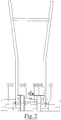
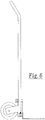
- the movable clamping element 4 (see FIG. 1) is adjustable, so that it can be adapted to the different plate formats. With the help of handle 18 (Fig. 7 + 8), the device becomes a portable device, whereby one can carry the plates. Models without wheels can also be produced if the panels only have to be relocated a short distance apart.
- the invention works as follows: The stone slabs to be laid are supplied in packages in a vertical position.
- the plate that must be picked up by the device must first be placed in a horizontal position. In a simple way, you can tip the plate over with your foot or hand and drop it on a rubber mat, for example.
- the device is positioned so that the fixed clamping element lies against the stone slab. By tilting the frame forward, the fixed clamping element falls over the plate at a certain moment (see Fig. 3).
- the plate is lifted up slightly by tilting the device backwards, one foot pressing on the wheel axle (see Fig. 4).
- the device is now driven with the clamped stone slab over the already paved surface to the destination.
- the clamped plate is now placed against the stone slabs already laid, as shown in FIG. 5.
- the front edge of the plate will first touch the floor, after which the plate as a whole will fall into place. If the slab to be laid has the lower edge of the left or right corner on the pavement that has already been laid, which can easily happen if it is incorrectly positioned, the slab can easily be brought into a good position by tilting the device back and forth. The clamping and frictional forces increase and decrease alternately, causing them to move longitudinally with respect to the fixed clamping element until the plate is perfectly in place.
Landscapes
- Engineering & Computer Science (AREA)
- Chemical & Material Sciences (AREA)
- Combustion & Propulsion (AREA)
- Transportation (AREA)
- Mechanical Engineering (AREA)
- Architecture (AREA)
- Civil Engineering (AREA)
- Structural Engineering (AREA)
- Road Paving Structures (AREA)
- Road Paving Machines (AREA)
Abstract
Description
- Die Erfindung bezieht sich auf eine Vorrichtung für den Transport und das Verlegen plattenförmiger Straßenpflasterelemente, wessen Gestell auf zwei Rädern stehend mit einer Klemme ausgestattet, mit der Hand zu verschieben ist.
- Eine ähnliche Maschine kennen wir aus der niederländischen Patentschrift 157366. Dieses bekannte Gerät ist geeignet, schwere Pflasterelemente in vertikaler Lage zu transportieren und an den Bestimmungsort zu legen.
Die Vorrichtung besteht aus einem auf zwei Rädern stehenden Gestell und einer vertikal und horizontal kippbaren Klemmvorrichtung, welche aus beweglichen Klemmplatten besteht. - Die Erfindung zielt auf eine Maschine, mit der es möglich wird, Pflasterelemente aus horizontaler Position festzuklemmen, hochzuheben und am Bestimmungsort auf einem zuvor geglätteten Sandbett wieder abzulegen.
Ausführung A der Vorrichtung wird bei schweren Betonpflasterelementen in den Formaten 40cm x 40cm, 50cm x 50cm, 40cm x 60cm usw. verwendet. Ausführung B der Maschine ist vor allem für das Anlegen von Bürgersteigen geeignet. - Wir sind der Ansicht, daß die den vorliegenden Antrag betreffende Erfindung die Arbeitsbedingungen bedeutend verbessert und die körperliche Anstrengung, welche einen Teil der Tätigkeit ausmacht, in entscheidendem Maße verringert wird. Die Vorrichtung ist sehr beweglich und ermöglicht dem Straßenbauer eine nahezu senkrechte Sicht auf den Arbeitsplatz. Dies erleichtert die korrekte Positionierung der Steinplatte in bezug auf die bereits gelegten Platten. Die Konstruktion des Geräts ist unkompliziert, es ist billig zu produzieren, wodurch es für die Vermietungsbranche prädestiniert ist. Modell A läßt sich leicht zu einem Steckkarren umbauen - es kann allso multifunktional eingesetzt werden.
- Die Maschine zeichnet sich dadurch aus, daß der eine Teil der Klemmvorrichtung an der Unterseite des Gestells befestigt ist, während der andere Teil in einem bestimmten Abstand davon mit einem Scharnier am Gestell angebracht ist. Diese Konstruktion ermöglicht es, den Abstand zwischen den Klemmelementen zu vergrößern, indem man das Gestell nach vorne kippt oder ihn zu verkleinern, indem man dieses nach hinten kippt.
Wird das Gestell mit dem festen Klemmelement gegen eine Steinplatte gesetzt, wonach es nach vorne gekippt wird, fällt das bewegliche Klemmelemet über die Steinplatte. Das Gestell wird nun nach hinten gekippt, wobei die Platte festgeklemmt und ein wenig hochgehoben wird. Beim nach hinten kippen muß das Gestell an der Unterseite blockiert werden, dies ist leicht zu bewerkstelligen, indem man einen Fuß auf die Radachse setzt. Die Steinplatte kann jetzt transportiert werden. Am Bestimmungsort wird die Maschine wieder nach vorne gekippt und zwar so, daß die Steinplatte an der Seite des festen Klemmelements gegen die bereits fertiggestellte Pflasterung anliegt. Indem man das Gestell in zunehmenden Maße vornüber kippt, berührt die Steinplatte mit der Vorderseite den Untergrund. Da Klemm- und Reibungskraft abnehmen, indem sich der Abstand der Klemmelemente vergrößert, fällt die Steinplatte zu einem bestimmten Zeitpunkt auf ihren Platz, wobei die Platten sehr eng an einander anschließen. Die Vorrichtung kann nun weggenommen werden, indem man das bewegliche Klemmelement mit dem Fuß hochhebt. - Die Erfindung soll anhand der folgenden Zeichnungen verdeutlicht werden:
- Fig. 1
- zeigt Modell A in Seitenansicht;
- Fig. 2
- zeigt Modell A in Hinteransicht;
- Fig. 3-5
- zeigen Modell A bei verschiedenen Arbeitsgängen;
- Fig. 6
- zeigt Modell A umgebaut zu einem Steckkarren;
- Fig. 7
- zeigt einen Durchschnitt der Seitenansicht von Modell B;
- Fig. 8
- zeigt Modell B in Hinteransicht.
- Die Erfindung besteht aus einem Rahmen 1 (16), welcher auf Rädern 9 (19) ruht und an der Unterseite mit einem festen Klemmelement 3 (13) ausgestattet ist. In einigem Abstand vom festen Klemmelement 3 (13) befindet sich am Rahmen 1 (16) ein Gelenklager 7 (17), an dem das Klemmelement 4 (14) gelenkig befestigt ist. Vorkehrungen 8 (20) begrenzen die Bewegungsfreiheit des Klemmelements 4 (14) in folgender Hinsicht:
- Die Vorrichtung bleibt in einem bestimmten Ruhestand stehen, ruhend einerseits auf den Rädern 9 (19) und andererseits auf der Außenkante des beweglichen Klemmelements 4 (14).
- Das rücklings Kippen des Gestells bewirkt ein Mitkippen der beweglichen Teilklemme 4 (14) zu einem bestimmten Zeitpunkt.
- Der kleine Achsenstand ist unablässig beim legen bestimmter Muster, wie z.B. dem sogenannten Mühlenflügel, bei dem vier Platten des Formats 60 cm x 40 cm ein Quadrat von 100 cm x 100 cm bilden. Der bei diesem Muster verwendbare Radstand beträgt maximal 20 cm. Das bewegliche Klemmelement 4 (s. Fig. 1) ist verstellbar, wodurch dieses an die unterschiedlichen Plattenformate angepaßt werden kann. Mithilfe von Handgriff 18 (Fig. 7 + 8) wird das Gerät zu einer tragbaren Vorrichtung, wobei man die Platten mittragen kann. Es können auch Modelle ohne Räder hergestellt werden, falls die Platten nur in einem geringen Abstand neu verlegt werden müssen.
- Die Erfindung funktioniert folgendermaßen:
Die zu verlegenden Steinplatten werden in vertikaler Lage in Paketen geliefert. Die Platte, die von der Vorrichtung aufgehoben werden muß, muß zuerst in horizontale Lage gebracht werden. Auf einfache Weise kann man mit dem Fuß oder mit der Hand die Platte umkippen und sie beispielsweise auf eine Gummimatte fallen lassen. Nun wird das Gerät so positioniert, daß das feste Klemmelement an der Steinplatte anliegt. Indem man das Gestell vornüber kippt, fällt das feste Klemmelement in einem bestimmten Moment über die Platte (s. Fig. 3). Die Platte wird geringfügig hochgehoben, indem man die Vorrichtung nun nach hinten kippt, wobei ein Fuß auf die Radachse drückt (s. Fig. 4). Das Gerät wird nun mit der festgeklemmten Steinplatte über die bereits gepflasterte Fläche zum Bestimmungsort gefahren.
Die eingeklemmte Platte wird nun so gegen die bereits verlegten Steinplatten angelegt, wie es in Figur 5 dargestellt ist. Kippt man das Gestell nun vornüber, wird zunächst die Vorderkante der Platte den Boden berühren, wonach die Platte als Ganze auf ihren Platz fallen wird. Sollte die zu verlegende Platte mit der Unterkante der linken oder rechten Ecke auf der bereits verlegten Pflasterung aufliegen, was bei falscher Positionierung leicht geschieht, kann man die Platte leicht in eine gute Position bringen, wenn man die Vorrichtung etwas hin und zurück kippt. Die Klemm- und Reibungskräfte nehmen abwechselnd zu und ab, wodurch sich die in bezug auf das feste Klemmelement in Längsrichtung verschiebt, bis die Platte perfekt auf ihrem Platz liegt. - Will man bereits bestehende Pflasterung entfernen, muß man einen bestimmten Abstand zwischen den zu entfernenden Platten und der übrigen Pflasterung schaffen, was sich leicht mit einem Spaten oder einer Plattenschaufel bewerkstelligen läßt. Die Vorrichtung wird nun so in Position gebracht, daß das unbewegliche Klemmelement an der zu entfernenden Platte anliegt, wobei sich die Räder im Sandbett befinden. Beim nach vorne Kippen wird das bewegliche Element zwischen den gerade geschaffenen Raum fallen. Nach dem Hochheben der Platte dreht man das Gerät im Sandbett und zieht es rückwärts auf die vorhandene Pflasterung. Es besteht die Möglichkeit, die Platten mit geringem Kraftaufwandt zu stapeln, indem man die Vorrichtung abwechselnd vom einen auf das andere Rad kippen läßt, wodurch Höhenunterschiede stufenweise überbrückbar sind.
Claims (7)
- Vorrichtung für das Transportieren und verlegen plattenförmiger Straßenpflasterelemente, bestehend aus einem mit der Hand fahrbaren, auf zwei Rädern ruhenden Gestell, welches mit einer Klemmvorrichtung ausgestattet ist, die sich dadurch auszeichnet, daß der eine Teil der Klemmvorrichtung 3 (13) an der Unterseite des Gestells befestigt ist, während der andere Teil 4 (14) in einigem Abstand hiervon gelenkig am Gestell befestigt ist.
- Vorrichtung gemäß Konklusion 1, mit dem Merkmal, daß das bewegliche Klemmelement 4 in der Länge verstellbar ist.
- Vorrichtung gemäß Konklusion 1, mit dem Merkmal, daß das bewegliche Klemmelement 4 (14) durch Ausstattung 8 (20) in der Bewegungsfreiheit eingeschränkt wird.
- Vorrichtung gemäß Konklusion 1, mit dem Merkmal, daß das feste Klemmelement 3 (13) ausgestattet ist mit zwei Anschlagnocken 2 (12).
- Vorrichtung gemäß Konklusion 1, mit dem Merkmal, daß das bewegliche Klemmelement 4 austauschbar ist durch das Zubehör für den Steckkarren.
- Vorrichtung gemäß Konklusion 1 und 5, mit dem Merkmal, daß der Achsenstand verstellbar ist.
- Vorrichtung gemäß Konklusion 1, mit dem Merkmal, daß Ausführung B von einem verstellbaren Handgriff 18 versehen ist.
Priority Applications (2)
| Application Number | Priority Date | Filing Date | Title |
|---|---|---|---|
| DE59410027T DE59410027D1 (de) | 1994-09-02 | 1994-09-02 | Vorrichtung für den Transport und das Verlegen plattenförmiger Strassenpflasterung |
| EP19940202507 EP0701023B1 (de) | 1994-09-02 | 1994-09-02 | Vorrichtung für den Transport und das Verlegen plattenförmiger Strassenpflasterung |
Applications Claiming Priority (1)
| Application Number | Priority Date | Filing Date | Title |
|---|---|---|---|
| EP19940202507 EP0701023B1 (de) | 1994-09-02 | 1994-09-02 | Vorrichtung für den Transport und das Verlegen plattenförmiger Strassenpflasterung |
Publications (2)
| Publication Number | Publication Date |
|---|---|
| EP0701023A1 true EP0701023A1 (de) | 1996-03-13 |
| EP0701023B1 EP0701023B1 (de) | 2002-01-09 |
Family
ID=8217157
Family Applications (1)
| Application Number | Title | Priority Date | Filing Date |
|---|---|---|---|
| EP19940202507 Expired - Lifetime EP0701023B1 (de) | 1994-09-02 | 1994-09-02 | Vorrichtung für den Transport und das Verlegen plattenförmiger Strassenpflasterung |
Country Status (2)
| Country | Link |
|---|---|
| EP (1) | EP0701023B1 (de) |
| DE (1) | DE59410027D1 (de) |
Cited By (3)
| Publication number | Priority date | Publication date | Assignee | Title |
|---|---|---|---|---|
| NO20064541A (no) * | 2006-10-06 | 2007-12-27 | Eriksengruppen | Anordning for løfte, transport og legging av belegningsstein. |
| WO2011078669A3 (en) * | 2009-12-22 | 2011-09-09 | T-Garden | Device for lifting and transporting objects |
| NL2022842B1 (en) | 2019-03-29 | 2020-10-06 | Albert Scheringa Frederik | Device for lifting and transporting objects |
Families Citing this family (1)
| Publication number | Priority date | Publication date | Assignee | Title |
|---|---|---|---|---|
| DE102008013973A1 (de) | 2008-03-12 | 2009-09-17 | Wolfgang Ody | Handkarre zum Aufnehmen und Verlegen von Plattenelementen |
Citations (5)
| Publication number | Priority date | Publication date | Assignee | Title |
|---|---|---|---|---|
| US4049284A (en) * | 1976-04-26 | 1977-09-20 | Ronald Capper | Combination hand truck and garden cart |
| GB2172249A (en) * | 1985-03-16 | 1986-09-17 | George Henry Jones | Trolley for facilitating movement and or laying of paving slabs or flags |
| GB2182307A (en) * | 1985-07-04 | 1987-05-13 | Charles John Downey | Paving slab laying trolley |
| DE9102053U1 (de) * | 1990-08-14 | 1991-10-10 | Breu, Michael, 8201 Frasdorf, De | |
| NL9300947A (nl) * | 1993-06-02 | 1995-01-02 | Hermanus Willem Johannes Spekm | Inrichting voor het transporteren en leggen van plaatvormige bestratingselementen. |
-
1994
- 1994-09-02 DE DE59410027T patent/DE59410027D1/de not_active Expired - Lifetime
- 1994-09-02 EP EP19940202507 patent/EP0701023B1/de not_active Expired - Lifetime
Patent Citations (5)
| Publication number | Priority date | Publication date | Assignee | Title |
|---|---|---|---|---|
| US4049284A (en) * | 1976-04-26 | 1977-09-20 | Ronald Capper | Combination hand truck and garden cart |
| GB2172249A (en) * | 1985-03-16 | 1986-09-17 | George Henry Jones | Trolley for facilitating movement and or laying of paving slabs or flags |
| GB2182307A (en) * | 1985-07-04 | 1987-05-13 | Charles John Downey | Paving slab laying trolley |
| DE9102053U1 (de) * | 1990-08-14 | 1991-10-10 | Breu, Michael, 8201 Frasdorf, De | |
| NL9300947A (nl) * | 1993-06-02 | 1995-01-02 | Hermanus Willem Johannes Spekm | Inrichting voor het transporteren en leggen van plaatvormige bestratingselementen. |
Cited By (3)
| Publication number | Priority date | Publication date | Assignee | Title |
|---|---|---|---|---|
| NO20064541A (no) * | 2006-10-06 | 2007-12-27 | Eriksengruppen | Anordning for løfte, transport og legging av belegningsstein. |
| WO2011078669A3 (en) * | 2009-12-22 | 2011-09-09 | T-Garden | Device for lifting and transporting objects |
| NL2022842B1 (en) | 2019-03-29 | 2020-10-06 | Albert Scheringa Frederik | Device for lifting and transporting objects |
Also Published As
| Publication number | Publication date |
|---|---|
| DE59410027D1 (de) | 2002-02-14 |
| EP0701023B1 (de) | 2002-01-09 |
Similar Documents
| Publication | Publication Date | Title |
|---|---|---|
| DE2817396A1 (de) | Geraet mit einem fahrbaren wagen mit einem aufrechtstehend angeordneten werkzeug, das zur bodenbearbeitung oder zum stampfen bestimmt ist | |
| DE4206704A1 (de) | Vorrichtung zum manipulieren von schweren werkstuecken | |
| EP0701023A1 (de) | Vorrichtung für den Transport und das Verlegen plattenförmiger Strassenpflasterung | |
| EP0240801B1 (de) | Abziehvorrichtung zum Herstellen eines Feinplanums | |
| DE2408585A1 (de) | Vorzugsweise selbstfahrender hubstapler | |
| DE1534201B1 (de) | Verfahren und Vorrichtung zum maschinellen Verlegen von Formsteinen | |
| DE3802034A1 (de) | Vorrichtung zum bewegen von schachtdeckeln | |
| CN209759975U (zh) | 一种较大地砖码放铺设装置 | |
| DE3811186C2 (de) | Gleitschalungsfertiger | |
| DE2629066A1 (de) | Vorrichtung zum aufreissen des pflasters einer strassendecke oder dergleichen, welche aus schweren pflastersteinen besteht | |
| DE7717723U1 (de) | Vorrichtung zum verlegen von bodenplatten | |
| EP3647254B1 (de) | Vorrichtung zum anheben von fahrzeugen | |
| DE102020007692B3 (de) | Plattenheber | |
| EP0384044B2 (de) | Fahrzeug zum Transportieren eines Stapels loser Steine | |
| DE1122893B (de) | Vorrichtung zum maschinellen Trennen von Asbestzementplatten von ihren Unterlagen und zum getrennten maschinellen Stapeln von Platten und Unterlagen | |
| DE238325C (de) | ||
| DE202009000678U1 (de) | Vorrichtung zum Angreifen, Anheben und Verlegen von Pflastersteinen | |
| DE10105587C2 (de) | Vorrichtung und Verfahren zum Egalisieren von Pflasterungen | |
| DE8134079U1 (de) | Selbstfahrende vorrichtung zum versetzen transportabler bauelemente | |
| DE2435369C3 (de) | Vorrichtung zum Heben und Senken eines einen geschlossenen Boden aufweisenden, kastenförmigen Fertigbauteils, insbesondere einer Fertiggarage | |
| DE2730628A1 (de) | Vorrichtung zum verlegen von strassenbelagelementen, insbesondere zum verlegen von plattenfoermigen verlegeeinheiten aus betonpflastersteinen | |
| NL9300947A (nl) | Inrichting voor het transporteren en leggen van plaatvormige bestratingselementen. | |
| DE19924843C1 (de) | Transporteinrichtung für mindestens ein zeitweilig aufzustellendes Straßenschild | |
| DE3031688A1 (de) | Verfahren und vorrichtung zum formgiessen insbesondere von beton | |
| DE202020000867U1 (de) | Universelle Verlegevorrichtung für großformatige Beton- und Feinsteinzeugplatten, großen Fliesen und ähnlichen Platten, Rasenkantensteinen, Betongittersteinen, Pflanzsteinen und ähnlichem |
Legal Events
| Date | Code | Title | Description |
|---|---|---|---|
| PUAI | Public reference made under article 153(3) epc to a published international application that has entered the european phase |
Free format text: ORIGINAL CODE: 0009012 |
|
| AK | Designated contracting states |
Kind code of ref document: A1 Designated state(s): BE DE FR |
|
| RBV | Designated contracting states (corrected) |
Designated state(s): BE DE FR |
|
| 17P | Request for examination filed |
Effective date: 19960821 |
|
| 17Q | First examination report despatched |
Effective date: 19990728 |
|
| GRAG | Despatch of communication of intention to grant |
Free format text: ORIGINAL CODE: EPIDOS AGRA |
|
| GRAG | Despatch of communication of intention to grant |
Free format text: ORIGINAL CODE: EPIDOS AGRA |
|
| GRAH | Despatch of communication of intention to grant a patent |
Free format text: ORIGINAL CODE: EPIDOS IGRA |
|
| GRAH | Despatch of communication of intention to grant a patent |
Free format text: ORIGINAL CODE: EPIDOS IGRA |
|
| GRAA | (expected) grant |
Free format text: ORIGINAL CODE: 0009210 |
|
| AK | Designated contracting states |
Kind code of ref document: B1 Designated state(s): BE DE FR |
|
| REF | Corresponds to: |
Ref document number: 59410027 Country of ref document: DE Date of ref document: 20020214 |
|
| ET | Fr: translation filed | ||
| PLBE | No opposition filed within time limit |
Free format text: ORIGINAL CODE: 0009261 |
|
| STAA | Information on the status of an ep patent application or granted ep patent |
Free format text: STATUS: NO OPPOSITION FILED WITHIN TIME LIMIT |
|
| 26N | No opposition filed | ||
| PGFP | Annual fee paid to national office [announced via postgrant information from national office to epo] |
Ref country code: FR Payment date: 20121015 Year of fee payment: 19 Ref country code: DE Payment date: 20121130 Year of fee payment: 19 Ref country code: BE Payment date: 20121025 Year of fee payment: 19 |
|
| BERE | Be: lapsed |
Owner name: *SPEKMAN HERMANUS WILLEM JOHANNES Effective date: 20130930 |
|
| REG | Reference to a national code |
Ref country code: FR Ref legal event code: ST Effective date: 20140530 |
|
| REG | Reference to a national code |
Ref country code: DE Ref legal event code: R119 Ref document number: 59410027 Country of ref document: DE Effective date: 20140401 |
|
| PG25 | Lapsed in a contracting state [announced via postgrant information from national office to epo] |
Ref country code: BE Free format text: LAPSE BECAUSE OF NON-PAYMENT OF DUE FEES Effective date: 20130930 |
|
| PG25 | Lapsed in a contracting state [announced via postgrant information from national office to epo] |
Ref country code: FR Free format text: LAPSE BECAUSE OF NON-PAYMENT OF DUE FEES Effective date: 20130930 Ref country code: DE Free format text: LAPSE BECAUSE OF NON-PAYMENT OF DUE FEES Effective date: 20140401 |