EP0700842B1 - Vorrichtung zum Ausgeben von Stückgütern - Google Patents
Vorrichtung zum Ausgeben von Stückgütern Download PDFInfo
- Publication number
- EP0700842B1 EP0700842B1 EP95890159A EP95890159A EP0700842B1 EP 0700842 B1 EP0700842 B1 EP 0700842B1 EP 95890159 A EP95890159 A EP 95890159A EP 95890159 A EP95890159 A EP 95890159A EP 0700842 B1 EP0700842 B1 EP 0700842B1
- Authority
- EP
- European Patent Office
- Prior art keywords
- rotor
- magazine
- latch
- arrangement according
- item
- Prior art date
- Legal status (The legal status is an assumption and is not a legal conclusion. Google has not performed a legal analysis and makes no representation as to the accuracy of the status listed.)
- Expired - Lifetime
Links
- 230000033001 locomotion Effects 0.000 claims description 21
- 238000000034 method Methods 0.000 claims description 11
- 230000004888 barrier function Effects 0.000 claims description 6
- 230000000694 effects Effects 0.000 claims description 3
- 239000013641 positive control Substances 0.000 claims 1
- 230000000977 initiatory effect Effects 0.000 description 3
- 230000011514 reflex Effects 0.000 description 3
- 230000005540 biological transmission Effects 0.000 description 2
- 230000000903 blocking effect Effects 0.000 description 1
- 230000005489 elastic deformation Effects 0.000 description 1
- 230000005284 excitation Effects 0.000 description 1
- 230000002349 favourable effect Effects 0.000 description 1
- 230000005484 gravity Effects 0.000 description 1
- 230000003287 optical effect Effects 0.000 description 1
- 230000001960 triggered effect Effects 0.000 description 1
Images



Classifications
-
- B—PERFORMING OPERATIONS; TRANSPORTING
- B65—CONVEYING; PACKING; STORING; HANDLING THIN OR FILAMENTARY MATERIAL
- B65G—TRANSPORT OR STORAGE DEVICES, e.g. CONVEYORS FOR LOADING OR TIPPING, SHOP CONVEYOR SYSTEMS OR PNEUMATIC TUBE CONVEYORS
- B65G1/00—Storing articles, individually or in orderly arrangement, in warehouses or magazines
- B65G1/02—Storage devices
- B65G1/04—Storage devices mechanical
- B65G1/06—Storage devices mechanical with means for presenting articles for removal at predetermined position or level
- B65G1/08—Storage devices mechanical with means for presenting articles for removal at predetermined position or level the articles being fed by gravity
-
- G—PHYSICS
- G07—CHECKING-DEVICES
- G07F—COIN-FREED OR LIKE APPARATUS
- G07F11/00—Coin-freed apparatus for dispensing, or the like, discrete articles
- G07F11/02—Coin-freed apparatus for dispensing, or the like, discrete articles from non-movable magazines
- G07F11/38—Coin-freed apparatus for dispensing, or the like, discrete articles from non-movable magazines in which the magazines are horizontal
- G07F11/42—Coin-freed apparatus for dispensing, or the like, discrete articles from non-movable magazines in which the magazines are horizontal the articles being delivered by motor-driven means
Definitions
- a device of this type is described in DE 29 52 764 A1 known.
- This known device is for output designed rod-shaped objects and has a magazine room on, which is formed by a flow channel, which by the edges are delimited by meandering slots is which are incorporated into several plates that are spaced are arranged parallel to each other. The number of plates depends on the length of the rod-shaped Objects.
- this through-channel is a rotor in the form of a star wheel arranged, the axis of rotation below the magazine room runs and which is provided with a drive.
- the magazine is provided with a floor, on which piece goods various Can slide length.
- the ratchet mechanism only requires short actuation paths and such can lock and the initiation of rotating the rotor with relative at high speed. Because the tangent direction of the Rotation of the rotor approximately with the sliding direction of the piece goods coinciding in the dispensing phase already results on Beginning of the rotor rotation a movement of the piece goods, whereby also a larger one for piece goods of different lengths or heights Output speed can be achieved than in known Devices.
- the latch mechanism in addition to the jack also has a jack nose and the Jack and the jack nose alternately in the circular path of the The ratchet wheel can be moved in and out and alternately lock the ratchet wheel and the ratchet nose at Move into the circular path of the ratchet wheel at one Tooth back of the ratchet wheel in the sense of turning the Ratchet wheel attacks. So it can be forcibly a rotational movement of the rotor in the discharge direction, whereby In general, the dispensing process is accelerated, since this is the general cargo column even a small contribution to the rotation of the rotor must afford. This can reduce the output speed be increased by at least 25%.
- the jack and the Jack nose connected to each other by a mechanism are the fixed positions of these two elements to each other specifies. It is - also in terms of structural simplification -
- an advantage if the jack and the Pawl nose are arranged on the pawl body.
- the jack and the jack nose Actuation of the latch body in an alternating manner on the Ratchet wheel and thus act on the rotor, and so one Forced control of the rotor rotation by one, the wing angle offset corresponding angle amount is reached.
- the blades of the rotor advantageously point in a tangential view a rectangular, trapezoidal or triangular shape, and they are through a corresponding recess at the end of the Movable magazine bottom. This allows the wings to a relatively large width on the underside of the piece goods act and it can the surface pressure between wing and General cargo can be kept low.
- the wing tips can also be used be provided with small rollers so that the general cargo is easier moved over them.
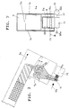
- the pawl 9a is from the Circular path of the ratchet wheel 7 by energizing the electromagnet 12, whereby the connecting joint 11 between the electromagnet 12 and pawl body 9 in the tightening direction 12a of the electromagnet 12 has been moved out. This is a rotational movement of the rotor 6 in the direction 5a of the output possible.
Landscapes
- Engineering & Computer Science (AREA)
- Mechanical Engineering (AREA)
- Physics & Mathematics (AREA)
- General Physics & Mathematics (AREA)
- Vending Machines For Individual Products (AREA)
- De-Stacking Of Articles (AREA)
Description
Claims (15)
- Vorrichtung (1) zum Ausgeben von Stückgütern (2a, 2b) aus Magazinen (3), die gegenüber der Vertikalen geneigt angeordnet sind und an ihrer unteren Stirnseite (4) eine Ausgebeöffnung (5) mit einem Ausgeber aufweisen, welcher durch einen in der Nähe der Ausgebeöffnung (5) angeordneten und gegen Drehung arretierbaren Rotor (6) mit mehreren symmetrisch zueinander versetzten radialen Flügeln (6a, 6b, 6c) gebildet ist, dessen Drehachse (8) unterhalb des Magazinraumes verläuft, und der mit einem Antrieb versehen ist, welche Flügel (6a, 6b, 6c) im Zuge der Drehung des Rotors (6) eine zum Teil durch das Magazin (3) verlaufende Umlaufbahn durchlaufen, wobei sich die Flügel (6a, 6b, 6c), welche je einen Ausgeber und einen Anschlag für die Stückgüter (2a, 2b) bilden, bei der Drehung des Rotors (6) in Rutschrichtung (5a) der Stückgüter (2a, 2b) im Magazin (3) bzw. in Ausgeberichtung der Stückgüter (2a, 2b) aus dem Magazin (3) bewegen, und hierbei jeweils ein Flügel zunächst einen Anschlag bildet, der nach Entriegelung des Rotors (6) von dem der Ausgebeöffnung benachbarten Stückgut (2a), gedreht wird, und der nachfolgende Flügel in das Magazin (3) eintritt und einen Anschlag für das nachfolgende Stückgut bildet, dadurch gekennzeichnet, daß zum Drehen und zum Arretieren des Rotors (6) ein Klinkenmechanismus aus einem mit dem Rotor (6) drehfest verbundenen Klinkenrad (7) und einer Klinke (9a), die auf einem schwenkbaren, mit einem Betätigungsmechanismus verbundenen Klinkenkörper (9) angeordnet und in die Kreisbahn des Klinkenrades (7) hinein- und wieder herausbewegbar ist, vorgesehen ist, und daß die Drehachse des Rotors (6) in oder unterhalb eines Bodens (3a) des Magazins (3) verläuft, und daß die Flügel (6a, 6b, 6c) des Rotors durch eine Öffnung (13) des Magazinbodens (3a) hindurchbewegbar sind.
- Vorrichtung nach Anspruch 1, dadurch gekennzeichnet, daß der Klinkenmechanismus außer der Klinke (9a) auch eine Klinkennase (9b) aufweist und die Klinke (9a) und die Klinkennase (9b) wechselweise in die Kreisbahn des Klinkenrades (7) hinein- und wieder herausbewegbar sind und abwechselnd das Klinkenrad (7) arretieren und die Klinkennase (9b) beim Hineinbewegen in die Kreisbahn des Klinkenrades (7) jeweils an einem Zahnrücken des Klinkenrades (7) im Sinne eines Weiterdrehens des Klinkenrades (7) angreift.
- Vorrichtung nach Anspruch 2, dadurch gekennzeichnet, daß die Klinke (9a) und die Klinkennase (9b) untereinander durch einen Mechanismus verbunden sind, der feste Positionen dieser beiden Elemente (9a, 9b) zueinander festlegt.
- Vorrichtung nach Anspruch 2, dadurch gekennzeichnet, daß die Klinke (9a) und die Klinkennase (9b) am Klinkenkörper (9) angeordnet sind.
- Vorrichtung nach Anspruch 4, dadurch gekennzeichnet, daß die Klinke (9a) und die Klinkennase (9b) bei Betätigung des Klinkenkörpers (9) in abwechselnder Weise auf das Klinkenrad (7) und damit auf den Rotor (6) einwirken, und so eine Zwangssteuerung der Rotordrehbewegung um einen, dem Flügelwinkelversatz entsprechenden Winkelbetrag erreicht wird.
- Vorrichtung nach einem der Ansprüche 1 bis 5, dadurch gekennzeichnet, daß der Betätigungsmechanismus mechanisch, elektrisch, elektromagnetisch oder durch einen pneumatischen Druckmittelzylinder antreibbar ist.
- Vorrichtung nach Anspruch 6, dadurch gekennzeichnet, daß der Betätigungsmechanismus mit einer die Klinke (9a) in Sperrstellung führenden Rückstellfeder (15) versehen ist.
- Vorrichtung nach einem der Ansprüche 1 bis 7, dadurch gekennzeichnet, daß der Klinkenkörper (9) Antriebsmittel aufweist, die sowohl hinsichtlich ihrer Geschwindigkeit als auch bezüglich ihrer Anpaßbarkeit an unterschiedlich lange Stückgüter (2a, 2b) über einen elektronischen Rechner regelbar sind.
- Vorrichtung nach einem der Ansprüche 1 bis 8, dadurch gekennzeichnet, daß der jeweils im Magazin vor dem der Ausgebeöffnung (5) benachbarten Stückgut (2a) befindliche Flügel (6a) des Rotors (6), wenn er in Ausgeberichtung gedreht wird, soweit geneigt wird, daß er gemeinsam mit dem nachfolgenden Flügel (6b), der dabei auf seiner Kreisbahn durch die Öffnung (13) im Magazinboden (3a) das dort befindliche Stückgut (2a) vom Magazinboden (3a) her berührt oder ein wenig anhebt, eine Rutschfläche (14) für dieses Stückgut (2a) bildet.
- Vorrichtung nach einem der Ansprüche 1 bis 9, dadurch gekennzeichnet, daß die Flügel (6a, 6b, 6c) des Rotors (6) in tangentialer Ansicht eine Rechteck-, Trapez- oder Dreieckform aufweisen, wobei die Öffnung (13) am ausgabeseitigen Ende des Magazinbodens (3a) ausgebildet ist.
- Vorrichtung nach einem der Ansprüche 1 bis 10, dadurch gekennzeichnet, daß die Magazine (3) einen U-förmigen Querschnitt haben, wobei der Steg dieses Querschnittes den Magazinboden (3a) bildet und die Schenkel die seitlichen Magazinwände (3b, 3c) bilden.
- Vorrichtung nach einem der vorhergehenden Ansprüche, dadurch gekennzeichnet, daß mehrere Magazine (3) parallel nebeneinander in einer vertikal geneigten Ebene angeordnet sind.
- Vorrichtung nach einem der Ansprüche 1 bis 12, dadurch gekennzeichnet, daß sie eine Lichtschranke (19) aufweist, deren Lichtstrahl (21) in der Nähe der Ausgebeöffnung (5) quer über sämtliche Magazinenden verläuft und von einem mehr als ein vorgewähltes Maß über die seitlichen Magazinwände (3b, 3c) hinausragenden Stückgut (2a, 2b) unterbrechbar ist.
- Vorrichtung nach einem der Ansprüche 1 bis 13, dadurch gekennzeichnet, daß sie Sensoren bzw. Schalter (16, 17, 18) aufweist, die an der Ausgebeöffnung (5), um das Gleiten eines Stückgutes (2a, 2b) hin zur Ausgebeöffnung (5) zu erfassen, im Bereich des vordersten festgehaltenen Stückgutes (2a) im Magazin (3), um das allfällige Nichtvorhandensein eines Stückgutes für einen Ausgebevorgang zu erfassen, und an einer im Drehbereich der Flügel (6a, 6b, 6c) liegenden Stelle, um die Drehbewegung des Rotors (6), und damit der Flügel, um den gewünschten Winkelbetrag zu erfassen, angeordnet sind und diese Sensoren bzw. Schalter (16, 17, 18) mit einem elektronischen Rechner in Verbindung stehen.
- Vorrichtung nach Anspruch 6, dadurch gekennzeichnet, daß der Klinkenkörper (9) mit einem als Antrieb dienenden Elektromagneten (12) verbunden ist und ein Sensor oder Schalter (16) vorgesehen ist, der das Abheben des der Ausgebeöffnung (5) nächstliegenden Stückgutes (2a) vom Magazinboden (3a) erfaßt und den Elektromagneten (12) steuert, wobei beim Abheben des Stückgutes (2a), welches beim In-Bewegung-kommen desselben auftritt, der Elektromagnet (12), der beim Einschalten im Sinne eines Drehens des Rotors (6) wirkt, abgeschaltet wird.
Applications Claiming Priority (2)
| Application Number | Priority Date | Filing Date | Title |
|---|---|---|---|
| AT0173194A AT402392B (de) | 1994-09-09 | 1994-09-09 | Vorrichtung zum ausgeben von stückgütern aus magazinen |
| AT1731/94 | 1994-09-09 |
Publications (2)
| Publication Number | Publication Date |
|---|---|
| EP0700842A1 EP0700842A1 (de) | 1996-03-13 |
| EP0700842B1 true EP0700842B1 (de) | 1998-01-07 |
Family
ID=3519791
Family Applications (1)
| Application Number | Title | Priority Date | Filing Date |
|---|---|---|---|
| EP95890159A Expired - Lifetime EP0700842B1 (de) | 1994-09-09 | 1995-09-08 | Vorrichtung zum Ausgeben von Stückgütern |
Country Status (5)
| Country | Link |
|---|---|
| US (1) | US5641161A (de) |
| EP (1) | EP0700842B1 (de) |
| AT (1) | AT402392B (de) |
| DE (1) | DE59501205D1 (de) |
| ES (1) | ES2112032T3 (de) |
Families Citing this family (7)
| Publication number | Priority date | Publication date | Assignee | Title |
|---|---|---|---|---|
| DE10124945A1 (de) * | 2001-05-21 | 2002-12-12 | Klaus Jurisch | Vereinzelungsvorrichtung |
| AT412082B (de) * | 2001-12-20 | 2004-09-27 | Neukam Helmut Ing | Stauvorrichtung mit einem auswerfer |
| JP5671910B2 (ja) * | 2010-07-28 | 2015-02-18 | トヨタ自動車株式会社 | 積込装置および積込システム |
| ITTO20131048A1 (it) * | 2013-12-19 | 2015-06-20 | Tecnilab S P A | Dispositivo e metodo di scarico per consentire lo scarico di uno o piu' articoli alla volta da una fila di articoli disposti su un ripiano |
| CN107745957A (zh) * | 2017-11-15 | 2018-03-02 | 上海仰康智能科技有限公司 | 一种步进式旋转机构及其发送装置和方法 |
| DE102019008379B4 (de) * | 2019-12-02 | 2021-11-25 | Interroll Holding Ag | Verfahren zur Übergabe eines Transportguts, Lagersystem und Verwenden eines Sensors |
| US12459735B2 (en) * | 2023-03-16 | 2025-11-04 | Toyota Motor Engineering & Manufacturing North America, Inc. | Apparatus, system, and method for automating parts delivery |
Family Cites Families (14)
| Publication number | Priority date | Publication date | Assignee | Title |
|---|---|---|---|---|
| US2393961A (en) * | 1944-07-19 | 1946-02-05 | American Can Co | Feeding mechanism |
| US2435526A (en) * | 1944-08-14 | 1948-02-03 | William D Young | Multiple compartment vending machine |
| US2877928A (en) * | 1955-04-29 | 1959-03-17 | Ideai Dispenser Co | Vending machine |
| US2956660A (en) * | 1957-10-14 | 1960-10-18 | American Can Co | Can vending machine |
| FR1326124A (fr) * | 1962-06-21 | 1963-05-03 | Rotax Ltd | Dispositif permettant de libérer un par un des objets sur une glissière inclinée |
| US3157292A (en) * | 1962-09-10 | 1964-11-17 | Thomas J Pachell | Billet unscrambler |
| SE392451B (sv) * | 1974-07-04 | 1977-03-28 | Hammars Mekaniska Verkstad Ab | Enstocksmatare |
| DE2952764C2 (de) * | 1979-12-29 | 1987-04-02 | Otto Dipl.-Ing. 6905 Schriesheim Konrad | Durchlauflager für stabförmige Gegenstände |
| DE3015203C2 (de) * | 1980-04-19 | 1984-08-30 | Hermann 8404 Wörth Kronseder | Sperrvorrichtung für Gefäßförderer |
| DE3102669C2 (de) * | 1981-01-28 | 1984-08-23 | Krones Ag Hermann Kronseder Maschinenfabrik, 8402 Neutraubling | Sperrvorrichtung für Gefäßförderer, insbesondere Flaschenförderer |
| DE3567194D1 (en) * | 1984-04-26 | 1989-02-09 | Michel Marchand | Devices for the automatic distribution of products and a warehouse devised with the aid of such devices |
| US4896792A (en) * | 1987-09-28 | 1990-01-30 | Michel Marchand | Automatic dispensing device for products and central warehouse or store constructed with such devices |
| US4928511A (en) * | 1988-12-13 | 1990-05-29 | Sequa Corporation | Rotary cup infeed |
| DE9110327U1 (de) * | 1991-08-21 | 1991-11-14 | Knapp Logistik Automation Ges.M.B.H., Graz | Vorrichtung zum Ausgeben von in Magazinen gestapelten Stückgütern |
-
1994
- 1994-09-09 AT AT0173194A patent/AT402392B/de not_active IP Right Cessation
-
1995
- 1995-09-06 US US08/523,893 patent/US5641161A/en not_active Expired - Fee Related
- 1995-09-08 ES ES95890159T patent/ES2112032T3/es not_active Expired - Lifetime
- 1995-09-08 EP EP95890159A patent/EP0700842B1/de not_active Expired - Lifetime
- 1995-09-08 DE DE59501205T patent/DE59501205D1/de not_active Expired - Fee Related
Also Published As
| Publication number | Publication date |
|---|---|
| DE59501205D1 (de) | 1998-02-12 |
| AT402392B (de) | 1997-04-25 |
| ES2112032T3 (es) | 1998-03-16 |
| ATA173194A (de) | 1996-09-15 |
| EP0700842A1 (de) | 1996-03-13 |
| US5641161A (en) | 1997-06-24 |
Similar Documents
| Publication | Publication Date | Title |
|---|---|---|
| DE3630191A1 (de) | Vorrichtung zur ausgabe von muenzenrollen | |
| DE1910157B2 (de) | ||
| AT402392B (de) | Vorrichtung zum ausgeben von stückgütern aus magazinen | |
| DE1298754B (de) | Selbstverkaeufer | |
| DE1262657B (de) | Selbstverkaeufer fuer einzelne Gegenstaende | |
| DE69504430T2 (de) | Vorrichtung zur Verarbeitung von ausgestossenen Druckplatten in einer Schablonendruckmaschine | |
| DE4303397A1 (de) | Vorrichtung und Verfahren zum Spritzen und Zusammensetzen von Formerzeugnissen | |
| DE2754542C2 (de) | ||
| DE3842935C1 (de) | ||
| DE1242923B (de) | Selbstverkaeufer fuer Flaschen, Buechsen u. dgl. | |
| DE1153234B (de) | Vorrichtung zur Herstellung von Faltschachteln | |
| DE3912971C1 (de) | ||
| DE1578189B1 (de) | Munitionsbehaelter | |
| EP0229264B1 (de) | Ausgabeaggregat für einen Selbstverkäufer | |
| DE2940014A1 (de) | Vorrichtung zum quertransport | |
| DE4310411C2 (de) | Münzausgeber für Unterhaltungs- und Warenautomaten | |
| DE3312120C2 (de) | ||
| DE3144531A1 (de) | Ausgabevorrichtung fuer spielgeraete | |
| DE1000284C2 (de) | Absetzvorrichtung fuer Ziegelsteine in Ziegeleien | |
| DE1774622C3 (de) | Vorrichtung zur Warenausgabe mit einem drehbaren Gutträger und einer drehbaren Austrageinrichtung | |
| DE1919743A1 (de) | Vorrichtung zum Abteilen von Kettenfadenwaechterlamellen aus einem Stapel und Hinreichen derselben zum Einziehen der Kettfaeden | |
| DE4344796C1 (de) | Münzausgabevorrichtung | |
| DE1761565C3 (de) | Vorrichtung zum Abheben eines Blattes von einem Blattstapel | |
| DE1481410C (de) | Vorrichtung zur Überführung stab förmiger Gegenstande aus einem Stau schacht in eine pneumatische Forderlei tung | |
| DE1928053C (de) | Einrichtung zum Stapeln von Flachteilen in Sammelbehältern |
Legal Events
| Date | Code | Title | Description |
|---|---|---|---|
| PUAI | Public reference made under article 153(3) epc to a published international application that has entered the european phase |
Free format text: ORIGINAL CODE: 0009012 |
|
| AK | Designated contracting states |
Kind code of ref document: A1 Designated state(s): DE ES FR GB IT |
|
| 17P | Request for examination filed |
Effective date: 19960404 |
|
| 17Q | First examination report despatched |
Effective date: 19961220 |
|
| GRAG | Despatch of communication of intention to grant |
Free format text: ORIGINAL CODE: EPIDOS AGRA |
|
| GRAG | Despatch of communication of intention to grant |
Free format text: ORIGINAL CODE: EPIDOS AGRA |
|
| GRAH | Despatch of communication of intention to grant a patent |
Free format text: ORIGINAL CODE: EPIDOS IGRA |
|
| GRAH | Despatch of communication of intention to grant a patent |
Free format text: ORIGINAL CODE: EPIDOS IGRA |
|
| GRAA | (expected) grant |
Free format text: ORIGINAL CODE: 0009210 |
|
| AK | Designated contracting states |
Kind code of ref document: B1 Designated state(s): DE ES FR GB IT |
|
| REF | Corresponds to: |
Ref document number: 59501205 Country of ref document: DE Date of ref document: 19980212 |
|
| ITF | It: translation for a ep patent filed | ||
| REG | Reference to a national code |
Ref country code: ES Ref legal event code: FG2A Ref document number: 2112032 Country of ref document: ES Kind code of ref document: T3 |
|
| GBT | Gb: translation of ep patent filed (gb section 77(6)(a)/1977) |
Effective date: 19980402 |
|
| ET | Fr: translation filed | ||
| PLBE | No opposition filed within time limit |
Free format text: ORIGINAL CODE: 0009261 |
|
| STAA | Information on the status of an ep patent application or granted ep patent |
Free format text: STATUS: NO OPPOSITION FILED WITHIN TIME LIMIT |
|
| 26N | No opposition filed | ||
| REG | Reference to a national code |
Ref country code: GB Ref legal event code: IF02 |
|
| PGFP | Annual fee paid to national office [announced via postgrant information from national office to epo] |
Ref country code: ES Payment date: 20050719 Year of fee payment: 11 |
|
| PGFP | Annual fee paid to national office [announced via postgrant information from national office to epo] |
Ref country code: DE Payment date: 20060628 Year of fee payment: 12 |
|
| PGFP | Annual fee paid to national office [announced via postgrant information from national office to epo] |
Ref country code: FR Payment date: 20060712 Year of fee payment: 12 |
|
| PGFP | Annual fee paid to national office [announced via postgrant information from national office to epo] |
Ref country code: GB Payment date: 20060906 Year of fee payment: 12 |
|
| PGFP | Annual fee paid to national office [announced via postgrant information from national office to epo] |
Ref country code: IT Payment date: 20060930 Year of fee payment: 12 |
|
| GBPC | Gb: european patent ceased through non-payment of renewal fee |
Effective date: 20070908 |
|
| PG25 | Lapsed in a contracting state [announced via postgrant information from national office to epo] |
Ref country code: DE Free format text: LAPSE BECAUSE OF NON-PAYMENT OF DUE FEES Effective date: 20080401 |
|
| REG | Reference to a national code |
Ref country code: FR Ref legal event code: ST Effective date: 20080531 |
|
| PG25 | Lapsed in a contracting state [announced via postgrant information from national office to epo] |
Ref country code: FR Free format text: LAPSE BECAUSE OF NON-PAYMENT OF DUE FEES Effective date: 20071001 |
|
| PG25 | Lapsed in a contracting state [announced via postgrant information from national office to epo] |
Ref country code: GB Free format text: LAPSE BECAUSE OF NON-PAYMENT OF DUE FEES Effective date: 20070908 |
|
| REG | Reference to a national code |
Ref country code: ES Ref legal event code: FD2A Effective date: 20070910 |
|
| PG25 | Lapsed in a contracting state [announced via postgrant information from national office to epo] |
Ref country code: ES Free format text: LAPSE BECAUSE OF NON-PAYMENT OF DUE FEES Effective date: 20070910 |
|
| PG25 | Lapsed in a contracting state [announced via postgrant information from national office to epo] |
Ref country code: IT Free format text: LAPSE BECAUSE OF NON-PAYMENT OF DUE FEES Effective date: 20070908 |