EP0700076B1 - Beschickungseinrichtung für Halbleiterbearbeitungsanlagen - Google Patents
Beschickungseinrichtung für Halbleiterbearbeitungsanlagen Download PDFInfo
- Publication number
- EP0700076B1 EP0700076B1 EP95103066A EP95103066A EP0700076B1 EP 0700076 B1 EP0700076 B1 EP 0700076B1 EP 95103066 A EP95103066 A EP 95103066A EP 95103066 A EP95103066 A EP 95103066A EP 0700076 B1 EP0700076 B1 EP 0700076B1
- Authority
- EP
- European Patent Office
- Prior art keywords
- gripper
- movable part
- feeding arrangement
- movement
- linear
- Prior art date
- Legal status (The legal status is an assumption and is not a legal conclusion. Google has not performed a legal analysis and makes no representation as to the accuracy of the status listed.)
- Expired - Lifetime
Links
Images



Classifications
-
- H—ELECTRICITY
- H10—SEMICONDUCTOR DEVICES; ELECTRIC SOLID-STATE DEVICES NOT OTHERWISE PROVIDED FOR
- H10P—GENERIC PROCESSES OR APPARATUS FOR THE MANUFACTURE OR TREATMENT OF DEVICES COVERED BY CLASS H10
- H10P72/00—Handling or holding of wafers, substrates or devices during manufacture or treatment thereof
- H10P72/50—Handling or holding of wafers, substrates or devices during manufacture or treatment thereof for positioning, orientation or alignment
-
- H—ELECTRICITY
- H10—SEMICONDUCTOR DEVICES; ELECTRIC SOLID-STATE DEVICES NOT OTHERWISE PROVIDED FOR
- H10P—GENERIC PROCESSES OR APPARATUS FOR THE MANUFACTURE OR TREATMENT OF DEVICES COVERED BY CLASS H10
- H10P72/00—Handling or holding of wafers, substrates or devices during manufacture or treatment thereof
- H10P72/30—Handling or holding of wafers, substrates or devices during manufacture or treatment thereof for conveying, e.g. between different workstations
- H10P72/34—Handling or holding of wafers, substrates or devices during manufacture or treatment thereof for conveying, e.g. between different workstations the wafers being stored in a carrier, involving loading and unloading
- H10P72/3411—Handling or holding of wafers, substrates or devices during manufacture or treatment thereof for conveying, e.g. between different workstations the wafers being stored in a carrier, involving loading and unloading involving loading and unloading of wafers
- H10P72/3412—Batch transfer of wafers
-
- Y—GENERAL TAGGING OF NEW TECHNOLOGICAL DEVELOPMENTS; GENERAL TAGGING OF CROSS-SECTIONAL TECHNOLOGIES SPANNING OVER SEVERAL SECTIONS OF THE IPC; TECHNICAL SUBJECTS COVERED BY FORMER USPC CROSS-REFERENCE ART COLLECTIONS [XRACs] AND DIGESTS
- Y10—TECHNICAL SUBJECTS COVERED BY FORMER USPC
- Y10S—TECHNICAL SUBJECTS COVERED BY FORMER USPC CROSS-REFERENCE ART COLLECTIONS [XRACs] AND DIGESTS
- Y10S414/00—Material or article handling
- Y10S414/135—Associated with semiconductor wafer handling
- Y10S414/14—Wafer cassette transporting
Definitions
- the invention relates to a loading device for Semiconductor processing systems for the implementation of a transport object a fixed part between two end positions between the end positions carries a drive linearly movable part, wherein on the movable part Gripper for the transport object is attached.
- SMIF boxes standard mechanical interface boxes
- the semiconductor wafers are inserted into compartments of a magazine, which is fixed in a suitable manner on the bottom of the SMIF box.
- the magazines are first removed from the transport containers. After that, an implementation is usually necessary, for the implementation of which various technical solutions have become known.
- EP 209 660 a cassette is transported from an SMIF elevator to an equipment elevator by an automated cassette manipulator by using a pivoting movement during the vertical up or down movement of the cassette.
- the use of rotating elements is intended to reduce the degree of particle generation compared to linearly moving elements.
- Similar solutions are also described in EP 238 541, in which the magazine is moved over predetermined movement curves through the use of motor-driven lever arms which are moved in the z direction with a separate lift.
- the known solutions Due to the mechanical design of the known solutions, in particular the effective area of the converter designed as a lever arm, which is moved past the magazine, or the closed structure, the laminar air flow required to maintain the clean room is severely disrupted or prevented. Coupling the transfer movement with the z movement unnecessarily extends the transport times and increases particle generation.
- the known solutions make it difficult to retrofit existing clean rooms with the SMIF system when retrofitting semiconductor processing systems, so that wafer magazines can be introduced into the machines under SMIF conditions and unpacked and transported there under clean room conditions.
- pneumatically operated linear drives have the disadvantage in end positions Speed control on both sides of the cylinder in a very short distance to brake using throttle check valves in the form of end position damping.
- the maximum speed is a few millimeters decelerated to zero. There are inevitable impacts on the Transport object.
- the object of the invention is therefore the flexibility in loading when excluded negatively impact reliability and clean room conditions To increase influences.
- the task is performed by a loading device for semiconductor processing systems Claim 1 solved, in the implementation of a transport object between two End positions a fixed part between the end positions by a drive linearly movable part carries, on the movable part a gripper for the Transport object is attached by at least a portion of the movement of the moving part with the linear movement a rotational movement of the Gripper is connected.
- the rotatable attachment of the gripper to the gripper arm one parallel to the plane of the linear movement and perpendicular to the linear movement self-directed axis of rotation.
- the first lever can be effective Lever length can be adjustable.
- the rotatable attachment has a perpendicular to Plane of the linear movement directed axis of rotation.
- a driver for a coupling rod mounted on the gripper in an eccentrically arranged ball joint connection and a first stop are advantageously fastened to a pull rod guided and mounted in recirculating ball guides and, when the gripper arm moves forward linearly due to its abutment against a second stop on the fixed part causing the drawbar and driver to remain.
- the gripper rotates in the rotatable attachment.
- the ball joint connection has an adjustable stop system which is acted upon by spring force.
- the location of the start of the rotation and the angle of rotation is by varying the Attachment of both the first stop on the drawbar and the second Stop on the base plate or changing the position of the coupling rod adjustable.
- Electrical control is preferably used to control the functions of the gripper between sensors and actuators of the Grerfer and a supply unit Signal and motor power supply on the fixed part only in the two End positions of the moving part.
- Assemblies with resilient contacts are provided for electrical contacting, of which the fixed part in the end positions of the moving part one assembly each and the moving part at least one additional assembly carries, the resilient contacts on the fixed part, which are electrically connected to the Supply unit are connected, the resilient contacts on the movable part, of which there are electrical connections to the sensors and actuators, are facing.
- the resilient contacts are advantageously designed as gold contacts, in Form of spring-loaded gold pins.
- a pneumatic linear drive is provided for the linear movement of the scraper.
- at least one pair of throttles acting in parallel with differently adjustable air passage quantities is provided for speed control for each direction of the linear movement on the cylinder of the pneumatic linear drive.
- the number of throttles taking effect in the direction of the linear movement is controlled as a function of the location of the moving part and the direction of the linear movement by sensor signals.
- throttle check valves are provided as throttles allow the throttling of exhaust air adjustable and air in the direction of movement let through freely.
- a supporting column 1 and a covered elevator drive 2 serve as support elements for a receptacle 3 on which a magazine container 4 is placed.
- a by the elevator drive 2 movable in the z direction, described in more detail in DE patent 43 26 309 C1 with a receiving arm is provided to carry out the removal and return of a magazine 5 located in the magazine container 4 for wafer-like objects.
- the magazine 5 is removed from the magazine container 4 together with its bottom and stands on a plate 6 which can be lowered out of the receptacle 3 and which contains actuators and sensors necessary for the SMIF technology. So it is z. B.
- the elevator has a movable part which is guided in a fixed part and can be moved between an upper removal and return position and a lower parking position.
- the upper removal and return position and the lower parking position each correspond to a first and a second end position of the movable part of the elevator.
- a linear drive 7 for a movable gripper 8 is fastened to the supporting column 1, the area of action of which lies above the magazine 5 located in the lower parking position and is directed perpendicular to the direction of travel of the elevator drive 2.
- the gripping arm 8 is provided with the gripping elements 9 and sensors (not shown here) for monitoring the gripping process.
- a supply unit 10 for signal and motor power supply for the linear drive 7, the gripper 8 with its gripping elements 9 and a pneumatic short-stroke cylinder 11 serving for z-adjustment with a roller guide 12 is accommodated.
- the entire device With a base plate 13, the entire device can be fastened to a semiconductor processing system via a mechanical interface.
- a suction device or a filter / fan unit can be attached between the column 1 and the elevator drive 2, the speed of which can be regulated.
- Operating and display elements are housed in the area of the receptacle 3.
- An external control electronics has a cable connection to the device, which consists of individual modules that can be assembled by different combinations to different systems with different movements; It is also possible, if necessary, that only individual movements, such. B. the vertical movement of the elevator are realized.
- a supporting base plate 14 receives a pneumatic linear cylinder 15 with an internal movable piston and a roller guide 16 arranged parallel to it.
- the linear cylinder 15 and the roller guide 16 are connected to one another via a gripper arm 17 as a movable part, on which the gripper 8 is fastened in an adjustable angular range about an axis XX directed parallel to the plane of the linear movement and perpendicular to the linear movement itself.
- a first lever 18 rotatable about an axis HH is provided, as the enlarged representation in FIG. 3 shows, which scans a link 19 during the linear movement.
- the link 19 has a height difference which is transmitted to a second lever 21 by a push rod 20 which is rotatably attached to the first lever 18 about an axis SS and which in turn establishes the connection between the push rod 20 and the gripper 8.
- the first lever 18 is designed so that its effective lever length and thus the angle of rotation of the gripper 8 is adjustable.
- the distance between the axis of rotation HH of the lever 18 and the engagement point in the axis SS of the connecting rod 20 serving as a coupling is changed via an adjusting pin 181 and fixed with a clamping screw 182. What is achieved by an invisible tension spring is that the first lever 18 is always in contact with the link 19 and thus the angle of rotation of the tilted gripper 8 is retained.
- the transfer of the height difference H of the link 19 to the second lever arm 21 causes a rotation of the gripper 8 and thus of the magazine 5 about the axis XX, so that the semiconductor wafers previously removable in the magazine 5 are now upward show and are so removable.
- the rotation is completed after a linear path determined in length and the end position is assumed.
- a lowering takes place via the short-stroke cylinder 11 and the magazine 5 is stored in a fixed manner.
- the gripper 8 decouples from the magazine 5 and is raised and returned to its rest position.
- the elevator drive 2 has previously moved the movable part of the elevator together with the plate 6 and the bottom of the magazine container 4 upwards into its first end position, so that the magazine container 4 is closed and thus released for changing the magazine.
- a magazine has been introduced into the semiconductor processing system, this can cause a lock door that may be present in its magazine movement space to be closed, or further magazines are introduced into the semiconductor processing system.
- the magazines are transported out of the semiconductor processing system in the reverse order.
- Assemblies 22, 23 and 24 are used for signal and motor current transmission from the supply unit 10 to actuators and sensors of the gripper 8, of which the assemblies 22 and 23 are mounted in a fixed position on the fixed part in the end positions of the movable part.
- the assembly 24 is attached to the gripper arm 17.
- the assemblies 22, 23 have resilient contacts 25, 26 which face the resilient contacts 27, 28 on the assembly 24.
- the gold pins of the contacts 27, 28 on the movable part are placed on their counterpart on the fixed part with the greatest possible pressure in order to achieve a small contact resistance.
- the required contact pressure is generated via the spring.
- the working stroke which is achieved by the suspension, means that there is a brief electrical contact before leaving the end positions.
- its electrical supply is interrupted. The supply of the gripper 8 is guaranteed only in the end positions, so that a magazine can be taken over or handed over.
- the valve 35 When moving from the end position 30 to the end position 31, the valve 35 is first opened by the sensor 32, as a result of which the throttle check valve 38 is switched on to the throttle check valve 37. According to the internal friction of the drive and the setting of the throttle check valves 37, 38, the piston has a relatively high final speed.
- valve 35 is closed and throttle check valve 38 is switched off.
- the speed of the piston decreases almost sinusoidally to zero until the end position 31.
- a gentle approach to the end position 31 is achieved.
- a vibration or movement of the wafers to be transported in the magazine is avoided.
- switching on the valve 36 connected to driving over the sensor 33 remains without influence. Only when the direction of travel is reversed from the end position 31 to the end position 30 is the throttle check valve 39 opened by switching on the valve 36 effective, and a movement sequence similar to that for the opposite takes place Direction already described.
- 150 mm / s are realized at distances between the end position and the sensor of 90 ... 120 mm.
- 2/2-way valves or 3/2-way valves with a closed outlet are used as valves.
- the throttle check valves 37, 38, 39 and 40 each allow the throttling of the exhaust air to be adjusted, the air being able to pass unhindered in the direction of movement.
- the throttle check valves 37 and 40 are set so that the end position to be approached is always reached with a so-called "creep speed" (extra slow) of the piston.
- creep speed extra slow
- the electronics 34 it is also possible to influence the speed when the piston starts.
- the maximum speed is only reached between the positions to be traversed at which the sensors 22 and 31 are arranged.
- the start-up and braking are carried out in the areas between the end position 30 and the sensor 33 or sensor 32 and the end position 31 or vice versa. With this solution it is possible to influence the speed of the piston with simple means.
- the linear drive 41 which, like the linear drive 7, can be adjusted in height in a slide bearing by the short-stroke cylinder 11, contains a guide 43 for a slide 44 on a base plate 42, to which a gripper arm 45 is fastened.
- the gripper man 45 In its upper section, the gripper man 45 has a pull rod 47 which is guided and supported by recirculating ball guides 46, on which a driver 48 and a first stop 49 are fastened through the gripper arm 45.
- the driver 48 is connected to the gripper 8 via a coupling rod 50.
- An eccentric ball joint connection 51 which has an adjustable stop system which is acted upon by spring force, is used for mounting the coupling rod 50.
- the gripper 8 is rotatably mounted on the gripper arm 45 by a gripper bearing 52, the axis of rotation YY of which is directed perpendicular to the plane of the linear movement.
- a second stop 53 is fastened so that when the gripper arm 45 moves forward linearly in the direction of the semiconductor processing system, the first stop 49 comes into contact with the pull rod 47 depending on its location.
- the pull rod 47 and thus the driver 48 for the coupling rod 50 remain with further linear movement and cause the gripper 8 to rotate about the axis YY of the rotatable fastening of the gripper 8 on the gripper arm 45.
- the location of the start of rotation and the angle of rotation can be adjusted by varying the fastening of both the first stop 49 on the pull rod 47 and the second stop 53 on the base plate 42. Such an effect is also associated with the change in the position of the coupling rod 50.
- a tension spring 62 is with the driver 48 and one of the Recirculating ball guides 46 are coupled to the gripper arm 45 and serves in the latter backward movement to take the starting position for the tie rod 47.
- the linear drive, the elevator drive and the drive for the gripping elements of the gripper separated from the clean room by a dustproof enclosure.
- the moving objects such as the gripper, its gripping elements and one element to accommodate the transport objects, which is not described here, in the Clean rooms protrude, border suction devices.
Landscapes
- Container, Conveyance, Adherence, Positioning, Of Wafer (AREA)
- Manipulator (AREA)
- Elimination Of Static Electricity (AREA)
- Crystals, And After-Treatments Of Crystals (AREA)
- Feeding, Discharge, Calcimining, Fusing, And Gas-Generation Devices (AREA)
- Electrical Discharge Machining, Electrochemical Machining, And Combined Machining (AREA)
- Sheets, Magazines, And Separation Thereof (AREA)
- Reciprocating Conveyors (AREA)
- Feeding Of Articles By Means Other Than Belts Or Rollers (AREA)
- Specific Conveyance Elements (AREA)
Description
Die Halbleiterscheiben sind in Fächer eines Magazins eingeschoben, das auf dem Boden der SMIF-Box in geeigneter Weise fixiert ist.
So wird nach EP 209 660 eine Kassette durch einen automatisierten Kassettenmanipulator von einem SMIF-Fahrstuhl zu einem Gerätefahrstuhl transportiert, indem eine Schwenkbewegung während der senkrechten Auf- oder Abbewegung der Kassette eingesetzt wird. Durch den Einsatz von Drehelementen soll das Maß der Partikelerzeugung gegenüber linear sich bewegenden Elementen herabgesetzt werden.
Ähnliche Lösungen sind auch in EP 238 541 beschrieben, bei denen das Umsetzen des Magazins über vorgegebene Bewegungskurven durch den Einsatz motorisch angetriebener Hebelarme erfolgt, die mit einem separaten Lift in z-Richtung verfahren werden.
Die Kopplung der Umsetzbewegung mit der z-Bewegung verlängert unnötig die Transportzeiten und erhöht die Partikelgenerierung.
Außerdem ist es mit den bekannten Lösungen schwierig, bei der Nachrüstung von Halbleiterbearbeitungsanlagen bereits bestehende Reinsträume mit dem SMIF-System zu komplettieren, so daß Wafermagazine unter SMIF-Bedingungen in die Maschinen eingebracht und dort unter Reinstraumbedingungen entpackt und transportiert werden können.
Außerdem können bei länger werdenden Transportwegen mitgeführte Kabel für die Signal- und Motorstromübertragung von dafür vorgesehenen Einrichtungen im feststehenden Teil der Vorrichtung auf den beweglichen Teil, insbesondere den Greifer mit seinen greifenden Elementen, zu Störungen führen und die Zuverlässigkeit negativ beeinflussen. Von Nachteil ist außerdem die mechanische Rückwirkung der Kabelverbindung auf das bewegliche Teil und die Möglichkeit einer Partikelgenerierung.
Außerdem weist die Kugelgelenkverbindung ein federkraftbeaufschlagtes, justierbares Anschlagsystem auf.
Zur Vermeidung von Stößen auf das Transportobjekt ist zur Geschwindigkeitssteuerung für jede Richtung der Linearbewegung am Zylinder des pneumatischen Linearantriebes mindestens ein Paar von parallel wirkenden Drosseln mit voneinander verschieden einstellbaren Luftdurchlaßmengen vorgesehen. Die Zahl der in Richtung der Linearbewegung wirksam werdenden Drosseln ist in Abhängigkeit vom Ort des beweglichen Teiles und der Richtung der Linearbewegung von Sensorsignalen gesteuert.
- Fig. 1
- eine Ansicht einer Beschickungseinrichtung zur Drehung eines Magazin in eine "Rückenlage" mit beweglichem Teil in einer Endlage
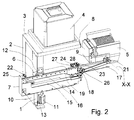
- Fig. 2
- die Beschickungseinrichtung gemäß Fig. 1 mit beweglichem Teil in der anderen Endlage
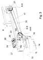
- Fig. 3
- in vergrößerter Darstellung die mechanische Kopplung der Drehbewegung in die "Rückerlage" an die Linearbewegung
- Fig. 4
- in Blockdarstellung die Geschwindigkeitssteuerung des Antriebes
- Fig. 5
- eine Ansicht einer Bechickungseinrichtung zur Drehung eines Magazins um eine senkrecht zur Ebene der Linearbewegung gerichtete Achse mit beweglichem Teil in einer Endlage
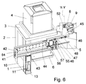
- Fig. 6
- die Beschickungseinrichtung gemäß Fig. 5 mit beweglichem Teil in der anderen Endlage
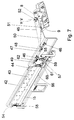
- Fig. 7
- in vergrößerter Darstellung die mechanische Kopplung der Drehbewegung um eine senkrecht zur Ebene der Linearbewegung gerichtete Achse an die Linearbewegung
Ein durch den Fahrstuhlantrieb 2 in z-Richtung verfahrbarer, in der DE-Patentschrift 43 26 309 C1näher beschriebener Fährstuhl mit einem Aufnahmearm ist vorgesehen, um die Entnahme und Rückführung eines in dem Magazinbehälter 4 befindlichen Magazins 5 für waferartige Objekte auszuführen.
In den vorliegenden Darstellungen ist das Magazin 5 aus dem Magazinbehälter 4 zusammen mit dessen Boden entnommen und steht auf einer aus der Aufnahme 3 heraus absenkbaren Platte 6, die für die SMIF-Technologie notwendige Aktoren und Sensoren enthält. So ist es z. B. erforderlich, den Zustand zu erfassen, ob ein Magazinbehälter 4 abgestellt ist oder nicht oder ob dieser geöffnet oder geschlossen ist.
Der Fahrstuhl besitzt einen beweglichen Teil, der in einem feststehenden Teil geführt, zwischen einer oberen Entnahme- und Rückführungsposition und einer unteren Abstellposition verfahrbar ist. Die obere Entnahme- und Rückführungsposition und die untere Abstellposition entsprechen jeweils einer ersten und einer zweiten Endlage des beweglichen Teiles des Fahrstuhles.
An der tragenden Säule 1 ist ein Linearantrieb 7 für einen beweglichen Greifer 8 befestigt, dessen Aktionsbereich oberhalb des sich in der unteren Abstellposition befindlichen Magazins 5 liegt und senkrecht zur Fahrtrichtung des Fahrstuhlantriebes 2 gerichtet ist.
Der Greifarm 8 ist mit den greifenden Elementen 9 und hier nicht dargestellten Sensoren zur Überwachung des Greifvorganges versehen.
Im unteren Bereich zwischen der Säule 1 und den Fahrstuhlantrieb 2 ist eine Versorgungseinheit 10 zur Signal- und Motorstromversorgung für den Linearantrieb 7, den Greifer 8 mit seinen greifenden Elementen 9 und einem zur z-Verstellung dienenden pneumatischen Kurzhubzylinder 11 mit einer Wälzführung 12 untergebracht.
Mit einer Grundplatte 13 ist die gesamte Einrichtung über ein mechanisches Interface an einer Halbleiterbearbeitungsanlage befestigbar.
Zur Erzeugung des mit einem Pfeil gekennzeichneten Luftstromes kann zwischen der Säule 1 und dem Fahrstuhlantrieb 2 eine Absaugvorrichtung oder eine Filter/Lüfter-Einheit angebracht werden, deren Drehzahl regelbar sein kann.
Im Bereich der Aufnahme 3 sind Bedien- und Anzeigeelemente untergebracht. Eine externe Steuerelektronik besitzt eine Kabelverbindung zu der Einrichtung, die aus einzelnen Modulen besteht, die durch unterschiedliche Kombinationen zu verschiedendsten Anlagen mit unterschiedlichsten Bewegungsabläufen montiert werden können; Es ist auch möglich, falls erforderlich, daß nur einzelne Bewegungsabläufe, wie z. B. die vertikale Bewegung des Fahrstuhles realisiert sind.
Zur Drehung des Greifers 8 um die Achse X-X ist, wie die vergrößerte Darstellung in Fig. 3 zeigt, ein um eine Achse H-H drehbarer erster Hebel 18 vorgesehen, der während der Linearbewegung eine Kulisse 19 abtastet. Die Kulisse 19 weist eine Höhendifferenz auf, die durch eine an dem ersten Hebel 18 um eine Achse S-S drehbar befestigte Schubstange 20 auf einen zweiten Hebel 21 übertragen wird, der wiederum die Verbindung zwischen der Schubstange 20 und den Greifer 8 herstellt.
Der erste Hebel 18 ist so konstruiert, daß seine wirksame Hebellänge und damit der Drehwinkel des Greifers 8 einstellbar ist. Über einen Einstellstift 181 wird der Abstand zwischen der Drehachse H-H des Hebels 18 und dem in der Achse S-S liegenden Eingriffspunkt der als Koppel dienenden Schubstange 20 verändert und mit einer Klemmschraube 182 fixiert.
Durch eine nicht sichtbare Zugfeder wird erreicht, daß der erste Hebel 18 immer an der Kulisse 19 anliegt und somit der Drehwinkel des gekippten Greifers 8 erhalten bleibt.
Kurz vor Erreichen der zweiten Endlage erfolgt durch die Übertragung der Höhendifferenz H der Kulisse 19 auf den zweiten Hebelarm 21 eine Drehung des Greifers 8 und damit des Magazins 5 um die Achse X-X, so daß die vorher im Magazin 5 nach vorn entnehmbaren Halbleiterscheiben nun nach oben zeigen und so entnehmbar sind.
Die Drehung ist nach einem in der Länge bestimmten Linearweg beendet und die Endlage wird eingenommen. Es erfolgt über den Kurzhubzylinder 11 eine Absenkung und das Magazin 5 wird fixiert abgelegt.
Der Greifer 8 koppelt vom Magazin 5 ab und wird angehoben in seine Ruhestellung zurückgefahren. Der Fahrstuhlantrieb 2 hat den beweglichen Teil des Fahrstuhles vorher zusammen mit der Platte 6 und dem Boden des Magazinbehälters 4 wieder nach oben in seine erste Endlage gefahren, so daß der Magazinbehälter 4 geschlossen und somit zum Magazinwechsel freigegebenen ist.
Nach dem Einbringen eines Magazins in die Halbleiterbearbeitungsanlage kann diese die Schließung einer eventuell vorhandenen Schleusentür in ihrem Magazinbewegungsraum veranlassen, oder es werden weitere Magazine in die Halbleiteibearbeltungsanlage eingebracht.
Das Heraustransportieren der Magazine aus der Halbleiterbearbeitungsanlage erfolgt in umgekehrter Reihenfolge.
Von den federnden Kontakten 25, 26, die als Goldkontakte ausgebildet sind, in Form von federnd in einer Hülse gehaltenen Goldstiften, bestehen elektrische Verbindungen zur Versorgungseinheit 10 und von den Kontakten 27, 28 zu den Sensoren und Aktoren des Greifers 8.
Befindet sich der reifer in der Endlage gemäß Fig. 1, berühren sich die die Kontakte 25 und 27 und in der Endlage gemäß Fig. 2 die Kontakte 26 und 28 und ermöglichen die Signal- und Motorstromübertragung.
Die Goldstifte der Kontakte 27, 28 am beweglichen Teil setzen mit möglichst großem Druck auf ihr Gegenstück am feststehenden Teil auf, um einen kleinen Übergangswiderstand zu erreichen. Der erforderliche Kontaktdruck wird über die Feder erzeugt.
Der Arbeitshub, der durch die Federung erreicht wird, bewirkt, daß vor dem Verlassen der Endlagen noch kurzzeitiger elektrischer Kontakt besteht.
Während der Linearbewegung bzw. Drehung des Greifers 8 ist dessen elektrische Versorgung unterbrochen. Nur in den Endlagen ist die Versorgung des Greifers 8 gewährleiset, so daß ein Magazin übernommen bzw. übergeben werden.
Von den Sensoren 32, 33 bestehen elektrische Verbindungen zu einer Elektronik 34, die die Impulssignale der Sensoren 32, 33 unter Beachtung der Fahrtrichtung in Signale zur Ansteuerung pneumatischer Ventile 35, 36 umwandelt. Mit jedem der pneumatischen Ventile 35, 36 ist ein Paar von Drosselrückschlagventilen 37, 38 und 39, 40 verbunden, die in der Abluftleitung des Zylinders angeordnet sind.
Bei einer Bewegung von der Endlage 30 in die Endlage 31 wird zunächst durch den Sensor 32 das Ventil 35 geöffnet, wodurch das Drosselrückschlagventil 38 dem Drosselrückschlagventil 37 zugeschaltet wird. Entsprechend der inneren Reibung des Antriebes und der Einstellung der Drosselrückschlagventile 37, 38 ergibt sich eine relativ hohe Endgeschwindigkeit des Kolbens.
Ohne Einfluß bleibt vorerst ein mit dem Überfahren des Sensors 33 verbundenes Einschalten des Ventils 36. Erst bei umgekehrter Fahrtrichtung von der Endlage 31 zur Endlage 30 wird das durch die Einschaltung des Ventils 36 geöffnete Drosselrückschlagventil 39 wirksam, und es erfolgt ein Bewegungsablauf wie für die entgegengesetzte Richtung bereits beschrieben. Das bei Betätigung des Sensor 32 ausgelöste Signal schließt das Ventil 36 und der Kolben verringert infolge der Abschaltung des Drosselrückschlagventils 39 seine Geschwindigkeit und wird durch die Wirkung des Drosselrückschlagventils 40 bis zur Endlage 30 auf Null abgebremst.
In ähnlicher Weise wie schon bei der Fahrt von der Endlage 30 zur Endlage 31 hat ein erneutes, mit der Betätigung des Sensors 32 verbundene Öden des Ventils 35 vorerst keine Wirkung. Bei der Fahrt in entgegengesetzter Richtung wird dann das betätigte Drosselrückschlagventil 38 wirksam.
Durch die Festlegung des Abstandes der Sensoren 32, 33 von den Endlagen 30, 31 und die Einstellung der beiden jeweils zusammengehörenden Drosselrückschlagventile 37 und 38 bzw. 39 und 40 sind die erreichbaren Endgeschwindigkeiten bestimmbar.
Im vorliegenden Ausführungsbeispiel werden bei Abständen Endlage - Sensor von 90 ... 120 mm Geschwindigkeiten des Kolbens von 100 ... 150 mm/s realisiert.
Als Ventile werden 2/2-Wegeventile oder 3/2-Wegeventile mit einem verschlossenen Ausgang verwendet.
Die Drosselrückschlagventile 37, 38, 39 und 40 lassen jeweils die Drosselung der Abluft einstellbar zu, wobei die Luft in Bewegungsrichtung ungehindert passieren kann.
Die Drosselrückschlagventile 37 und 40 sind dabei so eingestellt, daß mit einem sogenannten "Kriechgang" (extra langsam) des Kolbens immer die jeweils anzufahrende Endlage erreicht wird.
Mit Hilfe der Elektronik 34 ist es auch möglich, eine Beeinflussung der Geschwindigkeit beim Anfahren des Kolbens zu erreichen. Die maximale Geschwindigkeit wird nur jeweils zwischen den zu durchfahrenden Positionen, an denen die Sensoren 22 und 31 angeordnet sind, erreicht. Das Hochfahren und das Abbremsen erfolgt in den Bereichen zwischen der Endlage 30 und dem Sensor 33 bzw. Sensor 32 und der Endlage 31 oder umgekehrt.
Mit dieser Lösung ist es mit einfachen Mitteln möglich, die Geschwindigkeit des Kolbens zu beeinflussen.
Der Mitnehmer 48 ist über eine Koppelstange 50 mit dem Greifer 8 verbunden. Zur Lagerung für die Koppelstange 50 dient eine außermittig angeordnete Kugelgelenkverbindung 51, die ein federkraftbeaufschlagtes, justierbares Anschlagsystem aufweist. Der Greifer 8 ist durch ein Greiferlager 52, dessen Drehachse Y-Y senkrecht zur Ebene der Linearbewegung gerichtet ist, am Greiferarm 45 drehbar gelagert.
Auf der Grundplatte 42 ist ein zweiter Anschlag 53 so befestigt, daß bei vorwärtiger Linearbewegung des Greiferarms 45 in Richtung der Halbleiterbearbeitungsanlage der erste Anschlag 49 je nach seinem Ort der Befestigung auf der Zugstange 47 zur Anlage kommt. Dadurch bleibt die Zugstange 47 und damit der Mitnehmer 48 für die Koppelstange 50 bei weiterer Linearbewegung zurück und bewirkt eine rotatorische Bewegung der Greifers 8 um die Achse Y-Y der drehbaren Befestigung des Greifers 8 am Greiferarm 45.
Durch Variation der Befestigung sowohl des ersten Anschlages 49 an der Zugstange 47 als auch des zweiten Anschlages 53 an der Grundplatte 42 ist der Ort des Drehbeginns und der Drehwinkel einstellbar. Auch mit der Änderung der Lage der Koppelstange 50 ist ein derartiger Effekt verbunden.
Claims (15)
- Beschickungseinrichtung für Halbleiterbearbeitungsanlagen, mit einem feststehenden Teil (1, 14, 42), in dem ein bewegliches Teil (17; 44, 45) geführt, zwischen zwei Endlagen durch einen Antrieb (7; 41) linear verschiebbar und an dem ein Greifer (8) drehbar befestigt ist, mit dem ein Transportobjekt (5) in einer Endlage des beweglichen Teiles (17; 44, 45) ergreifbar und nach Verschieben des beweglichen Teiles (17; 44, 45) in die andere Endlage dort absetzbar ist bzw. umgekehrt, wobei zwischen dem Greifer (8) und dem beweglichen Teil eine mechanische Koppeleinrichtung (18, 19, 20, 21; 47, 48, 50, 53) besteht, mittels derer mindestens während eines Abschnitts des Verschiebeweges des beweglichen Teiles dessen lineare Verschiebebewegung in eine Drehbewegung des Greifers (8) relativ zum beweglichen Teil (44, 45) bis zum Erreichen eines vorgegebenen, einstellbaren Verdrehwinkels umgesetzt wird.
- Beschickungseinrichtung nach Anspruch 1, bei der der Greifer (8) drehbar an einem Greiferarm (17, 45) befestigt ist, der die Verbindung zu dem Antrieb (7, 41) bildet.
- Beschickungseinrichtung für Halbleiterbearbeitungsanlagen nach Anspruch 2, bei der das feststehende Teil (1, 14) in Höhenrichtung verstellbar ist, die lineare Verschiebung des beweglichen Teiles (17) senkrecht hierzu verläuft und der Greifer (8) am Greiferarm (17) um eine senkrecht zur linearen Verschiebebewegung des beweglichen Teiles angeordnete sowie in einer zur Höhenverstellrichtung des feststehenden Teiles (1, 14) senkrechten Ebene liegende Achse (X-X) verdrehbar ist.
- Beschickungseinrichtung nach Anspruch 3, bei der die mechanische Koppeleinrichtung (18-21) für den Greifer (8) einen mit dem Greiferarm (17) verbundenen ersten Hebel (18) aufweist, der während der linearen Bewegung des beweglichen Teiles eine Kulisse (19), die eine Höhendifferenz aufweist, abtastet und der über eine drehbar befestigte Schubstange (20) mit einem am Greifer (8) befestigten zweiten Hebel (21) zur Übertragung der Höhendifferenz und zur Umsetzung der linearen Bewegung in die Drehbewegung des Greifers (8) verbunden ist.
- Beschickungseinrichtung nach Anspruch 4, bei der der erste Hebel (18) zur Einstellung des Verdrehwinkels des Greifers (8) in seiner wirksamen Hebellänge einstellbar ist.
- Beschickungseinrichtung nach Anspruch 2, bei welcher das feststehende Teil in Höhenrichtung verstellbar ist, wobei der Greifer (8) am Greiferarm (45) um eine parallel zur Höhenverstellrichtung des feststehenden Teiles (14) liegende Achse (Y-Y) verdrehbar ist.
- Beschickungseinrichtung nach Anspruch 6, bei der die mechanische Koppeleinrichtung eine in Kugelumlaufführungen (46) geführte und gelagerte Zugstange (47) aufweist, an der ein Mitnehmer (48) für eine am Greifer (8) in einer außermittig angeordneten Kugelgelenkverbindung (51) gelagerte Koppelstange (50) sowie ein erster Anschlag (49) befestigt sind, der bei der linearen Bewegung des Greiferarms (45) in Vorwärtsrichtung an einem zweiten, am feststehenden Teil (42) angebrachten Anschlag (53) zur Anlage kommt und dadurch bei Fortsetzung der linearen Bewegung des bewegten Teiles (44, 45) durch ein Zurückbleiben der Zugstange (47) und des Mitnehmers (48) eine Verdrehung des Greifers (8) verursacht.
- Beschickungseinrichtung nach Anspruch 7, bei der die Kugelgelenkverbindung (51) ein federkraftbeaufschlagtes, justierbares Anschlagssystem aufweist.
- Beschickungseinrichtung nach Anspruch 8, bei der der Ort des Beginns der Verdrehung und der Verdrehwinkel des Greifers (8) durch Veränderung der Befestigung sowohl des ersten Anschlages (49) an der Zugstange (47) als auch des zweiten Anschlages (53) am feststehenden Teil (42) oder durch Veränderung der Lage der Koppelstange (50) einstellbar ist.
- Beschickungseinrichtung nach einem der Ansprüche 1 bis 9, bei der zur Steuerung der Funktionen des Greifers (8) eine elektrische Kontaktierung zwischen Sensoren und Aktoren des Greifers (8) und einer Versorgungseinheit (10) zur Signal- und Motorstromversorgung am feststehenden Teil (1, 14) ausschließlich in den beiden Endlage des beweglichen Teiles (17;44, 45) erfolgt.
- Beschickungseinrichtung nach Anspruch 10, bei der zur elektrischen Kontaktierung Baugruppen (22-24, 54-57) mit federnden Kontakten (25-27, 58-61) vorgesehen sind, von denen das feststehende Teil in den Endlagen des beweglichen Teiles jeweils eine Baugruppe (22, 23; 54, 55) und das bewegliche Teil mindestens eine weitere Baugruppe (24, 56, 57) trägt, wobei die federnden Kontakte (25, 26, 58, 59) am feststehenden Teil, die elektrisch mit der Versorgungseinheit (10) verbunden sind, den federnden Kontakten (27, 60, 61) am beweglichen Teil, von denen elektrische Verbindungen zu den Sensoren und Aktoren bestehen, zugewandt sind.
- Beschickungseinrichtung nach Anspruch 11, bei der die federnden Kontakte (25-27; 58-61) als Goldkontakte in Form von federnd in einer Hülse gehaltenen Goldstiften ausgebildet sind.
- Beschickungseinrichtung nach einem der Ansprüche 1 bis 12, bei der für die lineare Bewegung des Greifers (8) ein pneumatischer Linearantrieb (7, 41) vorgesehen ist.
- Beschickungseinrichtung nach Anspruch 13, bei der zur Geschwindigkeitssteuerung für jede Richtung der linearen Bewegung an dem Zylinder (15) des pneumatischen Linearantriebs (7, 41) mindestens ein Paar von parallel wirkenden Drosseln mit voneinander verschieden einstellbaren Luftdurchlaßmengen vorgesehen und die Anzahl der in Richtung der linearen Bewegung wirksam werdenden Drosseln in Abhängigkeit vom Ort des beweglichen Teiles und der Richtung der linearen Bewegung von Sensorsignalen gesteuert ist.
- Beschickungseinrichtung nach Anspruch 14, bei der als Drosseln Drosselrückschlagventile (37-40) vorgesehen sind, mit denen die Drosselung von Abluft einstellbar ist und welche die Luft in Bewegungsrichtung ungehindert durchlassen.
Applications Claiming Priority (2)
| Application Number | Priority Date | Filing Date | Title |
|---|---|---|---|
| DE4430844 | 1994-08-31 | ||
| DE4430844A DE4430844C1 (de) | 1994-08-31 | 1994-08-31 | Beschickungseinrichtung für Halbleiterbearbeitungsanlagen |
Publications (2)
| Publication Number | Publication Date |
|---|---|
| EP0700076A1 EP0700076A1 (de) | 1996-03-06 |
| EP0700076B1 true EP0700076B1 (de) | 2000-08-16 |
Family
ID=6526973
Family Applications (1)
| Application Number | Title | Priority Date | Filing Date |
|---|---|---|---|
| EP95103066A Expired - Lifetime EP0700076B1 (de) | 1994-08-31 | 1995-03-03 | Beschickungseinrichtung für Halbleiterbearbeitungsanlagen |
Country Status (8)
| Country | Link |
|---|---|
| US (1) | US5715929A (de) |
| EP (1) | EP0700076B1 (de) |
| JP (1) | JP2703740B2 (de) |
| KR (1) | KR0173521B1 (de) |
| AT (1) | ATE195609T1 (de) |
| DE (2) | DE4430844C1 (de) |
| SG (1) | SG42758A1 (de) |
| TW (1) | TW301016B (de) |
Families Citing this family (7)
| Publication number | Priority date | Publication date | Assignee | Title |
|---|---|---|---|---|
| JPH10107122A (ja) * | 1996-10-01 | 1998-04-24 | Tokyo Electron Ltd | 被処理基板カセットの搬入装置 |
| JPH10147432A (ja) * | 1996-11-20 | 1998-06-02 | Tokyo Electron Ltd | カセットチャンバ |
| DE19806852C1 (de) * | 1998-02-19 | 1999-08-12 | Jenoptik Jena Gmbh | Sicherheitsvorrichtung für ein Transportsystem |
| FI110506B (fi) * | 2000-12-20 | 2003-02-14 | Outokumpu Oy | Laitteisto levymäisen tuotteen siirtämiseksi asemalta toiselle |
| US6866460B2 (en) * | 2001-07-16 | 2005-03-15 | Semitool, Inc. | Apparatus and method for loading of carriers containing semiconductor wafers and other media |
| US6726429B2 (en) | 2002-02-19 | 2004-04-27 | Vertical Solutions, Inc. | Local store for a wafer processing station |
| KR100974468B1 (ko) * | 2009-06-12 | 2010-08-10 | 한명진 | 양방향 풍력발전기 |
Family Cites Families (19)
| Publication number | Priority date | Publication date | Assignee | Title |
|---|---|---|---|---|
| US2840219A (en) * | 1957-04-30 | 1958-06-24 | Newart Mfg Company | Automatic rack un-loader and loader for plating machines |
| US3913749A (en) * | 1974-08-12 | 1975-10-21 | Fluoroware Systems Corp | Wafer basket transfer apparatus |
| US4119211A (en) * | 1976-10-22 | 1978-10-10 | Western Electric Company, Inc. | Method and apparatus for transferring articles while re-establishing their orientation |
| JPS5743399A (en) * | 1980-08-27 | 1982-03-11 | Matsushita Electric Works Ltd | Device for firing discharge lamp |
| JPS60180789A (ja) * | 1984-02-25 | 1985-09-14 | ソニー株式会社 | クリ−ンル−ム内作業ロボツト装置 |
| JPS60259389A (ja) * | 1984-06-04 | 1985-12-21 | 日産自動車株式会社 | オ−トロ−ダ |
| US4705444A (en) * | 1985-07-24 | 1987-11-10 | Hewlett-Packard Company | Apparatus for automated cassette handling |
| US4674936A (en) * | 1985-08-26 | 1987-06-23 | Asyst Technologies | Short arm manipulator for standard mechanical interface apparatus |
| DE3686943T2 (de) * | 1985-08-26 | 1993-02-18 | Asyst Technologies | Manipulator fuer mechanische standardkoppelsysteme. |
| GB8709064D0 (en) * | 1986-04-28 | 1987-05-20 | Varian Associates | Wafer handling arm |
| US4770590A (en) * | 1986-05-16 | 1988-09-13 | Silicon Valley Group, Inc. | Method and apparatus for transferring wafers between cassettes and a boat |
| US4808059A (en) * | 1986-07-15 | 1989-02-28 | Peak Systems, Inc. | Apparatus and method for transferring workpieces |
| DE3637880C2 (de) * | 1986-11-06 | 1994-09-01 | Meissner & Wurst | Transportierbares Behältnis zur Handhabung von Halbleiterelementen während ihrer Herstellung sowie Verfahren zur partikelfreien Übergabe von Produkten |
| BE1000990A3 (nl) * | 1987-10-09 | 1989-05-30 | Picanol Nv | Inrichting voor het op elkaar aansluiten van onderling verplaatsbare elementen, en transportinrichting die eerstgenoemde inrichting toepast. |
| US5064337A (en) * | 1988-07-19 | 1991-11-12 | Tokyo Electron Limited | Handling apparatus for transferring carriers and a method of transferring carriers |
| DE4023772A1 (de) * | 1989-08-31 | 1991-03-14 | Gold Star Electronics | Vorrichtung zum beschicken und entladen von huelsen fuer ein ic-pruefgeraet |
| US5013213A (en) * | 1990-04-20 | 1991-05-07 | Kar Enterprises, Inc. | Automatic denesting machine |
| KR940005216Y1 (ko) * | 1991-01-31 | 1994-08-05 | 삼성전자 주식회사 | 전자 부품 이송 장치 |
| DE4326309C1 (de) * | 1993-08-05 | 1994-09-15 | Jenoptik Jena Gmbh | Vorrichtung zum Transport von Wafermagazinen |
-
1994
- 1994-08-31 DE DE4430844A patent/DE4430844C1/de not_active Expired - Fee Related
-
1995
- 1995-01-28 TW TW084100863A patent/TW301016B/zh active
- 1995-03-03 EP EP95103066A patent/EP0700076B1/de not_active Expired - Lifetime
- 1995-03-03 DE DE59508643T patent/DE59508643D1/de not_active Expired - Fee Related
- 1995-03-03 AT AT95103066T patent/ATE195609T1/de not_active IP Right Cessation
- 1995-04-28 US US08/430,407 patent/US5715929A/en not_active Expired - Lifetime
- 1995-05-19 JP JP7121750A patent/JP2703740B2/ja not_active Expired - Lifetime
- 1995-06-20 SG SG1995000693A patent/SG42758A1/en unknown
- 1995-07-31 KR KR1019950023475A patent/KR0173521B1/ko not_active Expired - Fee Related
Also Published As
| Publication number | Publication date |
|---|---|
| KR960007401A (ko) | 1996-03-22 |
| ATE195609T1 (de) | 2000-09-15 |
| DE4430844C1 (de) | 1996-02-22 |
| JP2703740B2 (ja) | 1998-01-26 |
| KR0173521B1 (ko) | 1999-04-01 |
| DE59508643D1 (de) | 2000-09-21 |
| EP0700076A1 (de) | 1996-03-06 |
| TW301016B (de) | 1997-03-21 |
| JPH08181188A (ja) | 1996-07-12 |
| SG42758A1 (en) | 1997-10-17 |
| US5715929A (en) | 1998-02-10 |
Similar Documents
| Publication | Publication Date | Title |
|---|---|---|
| DE60131895T2 (de) | Vorrichtung zur beladung eines behälters, der in einem fims-system verwendung findet | |
| DE3686614T2 (de) | Vorrichtung und verfahren zum automatisierten manipulieren einer kassette. | |
| EP0923111B1 (de) | Halbleiter-Montageeinrichtung mit einem hin und her geführten Chipgreifer | |
| DE1959093C2 (de) | Vorrichtung zur Handhabung leicht zerbrechlicher Werkstücke, insbesondere von Plättchen für die Herstellung von Halbleiterbauelementen | |
| EP0696817A1 (de) | Einrichtung zur Kopplung von Be- und Entladegeräten mit Halbleiterbearbeitungsmaschinen | |
| EP0240788B1 (de) | Röntgenblattfilmkassetten-Beladegerät | |
| DE69005021T2 (de) | Schwenkbare Werkstück-Entnahmevorrichtung. | |
| DE4430846C2 (de) | Einrichtung zur Umsetzung eines Transportobjektes zwischen zwei Endlagen | |
| EP0664050B1 (de) | Vorrichtung zum transport von wafermagazinen | |
| DE4201289C2 (de) | Vorrichtung zur Handhabung von Werkstücken | |
| EP0427222B1 (de) | Vorrichtung zur Herstellung von Druckplatten | |
| DE60303325T2 (de) | Haltevorrichtung für Platten | |
| DE10128904A1 (de) | Substrat-Verarbeitungsvorrichtung | |
| DE4430844C1 (de) | Beschickungseinrichtung für Halbleiterbearbeitungsanlagen | |
| CH696103A5 (de) | Halbleiter-Montageeinrichtung. | |
| DE3686943T2 (de) | Manipulator fuer mechanische standardkoppelsysteme. | |
| DE102020131035A1 (de) | Lineares Transportsystem mit Objektübergabe | |
| EP0955108A1 (de) | Traversen-Dreiachstransfer | |
| DE2005825A1 (de) | Vorrichtung zum Zuführen von Gegenständen, z.B. elektronischen Bauteilen, in bestimmter Reihenfolge aus Magazinen in eine Einsetzvorrichtung | |
| DD229325A5 (de) | Betaetigungsvorrichtung zur verwendung in einer giessereianlage | |
| DE69621443T2 (de) | Verbesserte spannrahmen-wechselvorrichtung | |
| DE10023241C2 (de) | Transfereinrichtung und Verfahren zur Steuer einer Transfereinrichtung | |
| DE3712064C2 (de) | ||
| DE4416843C2 (de) | Zick-Zack-Vorschubeinrichtung | |
| DE102012103823A1 (de) | Anschlagmodul zum positionsgenauen Anhalten eines Gegenstands |
Legal Events
| Date | Code | Title | Description |
|---|---|---|---|
| PUAI | Public reference made under article 153(3) epc to a published international application that has entered the european phase |
Free format text: ORIGINAL CODE: 0009012 |
|
| AK | Designated contracting states |
Kind code of ref document: A1 Designated state(s): AT BE CH DE ES FR GB IE IT LI NL |
|
| 17P | Request for examination filed |
Effective date: 19960115 |
|
| 17Q | First examination report despatched |
Effective date: 19980625 |
|
| GRAG | Despatch of communication of intention to grant |
Free format text: ORIGINAL CODE: EPIDOS AGRA |
|
| GRAG | Despatch of communication of intention to grant |
Free format text: ORIGINAL CODE: EPIDOS AGRA |
|
| GRAH | Despatch of communication of intention to grant a patent |
Free format text: ORIGINAL CODE: EPIDOS IGRA |
|
| GRAH | Despatch of communication of intention to grant a patent |
Free format text: ORIGINAL CODE: EPIDOS IGRA |
|
| GRAA | (expected) grant |
Free format text: ORIGINAL CODE: 0009210 |
|
| AK | Designated contracting states |
Kind code of ref document: B1 Designated state(s): AT BE CH DE ES FR GB IE IT LI NL |
|
| PG25 | Lapsed in a contracting state [announced via postgrant information from national office to epo] |
Ref country code: NL Free format text: LAPSE BECAUSE OF FAILURE TO SUBMIT A TRANSLATION OF THE DESCRIPTION OR TO PAY THE FEE WITHIN THE PRESCRIBED TIME-LIMIT Effective date: 20000816 Ref country code: IT Free format text: LAPSE BECAUSE OF FAILURE TO SUBMIT A TRANSLATION OF THE DESCRIPTION OR TO PAY THE FEE WITHIN THE PRESCRIBED TIME-LIMIT;WARNING: LAPSES OF ITALIAN PATENTS WITH EFFECTIVE DATE BEFORE 2007 MAY HAVE OCCURRED AT ANY TIME BEFORE 2007. THE CORRECT EFFECTIVE DATE MAY BE DIFFERENT FROM THE ONE RECORDED. Effective date: 20000816 Ref country code: ES Free format text: THE PATENT HAS BEEN ANNULLED BY A DECISION OF A NATIONAL AUTHORITY Effective date: 20000816 |
|
| REF | Corresponds to: |
Ref document number: 195609 Country of ref document: AT Date of ref document: 20000915 Kind code of ref document: T |
|
| REG | Reference to a national code |
Ref country code: CH Ref legal event code: EP |
|
| REG | Reference to a national code |
Ref country code: IE Ref legal event code: FG4D Free format text: GERMAN |
|
| REF | Corresponds to: |
Ref document number: 59508643 Country of ref document: DE Date of ref document: 20000921 |
|
| ET | Fr: translation filed | ||
| GBT | Gb: translation of ep patent filed (gb section 77(6)(a)/1977) |
Effective date: 20010103 |
|
| PG25 | Lapsed in a contracting state [announced via postgrant information from national office to epo] |
Ref country code: AT Free format text: LAPSE BECAUSE OF NON-PAYMENT OF DUE FEES Effective date: 20010303 |
|
| PG25 | Lapsed in a contracting state [announced via postgrant information from national office to epo] |
Ref country code: LI Free format text: LAPSE BECAUSE OF NON-PAYMENT OF DUE FEES Effective date: 20010331 Ref country code: CH Free format text: LAPSE BECAUSE OF NON-PAYMENT OF DUE FEES Effective date: 20010331 Ref country code: BE Free format text: LAPSE BECAUSE OF NON-PAYMENT OF DUE FEES Effective date: 20010331 |
|
| PG25 | Lapsed in a contracting state [announced via postgrant information from national office to epo] |
Ref country code: IE Free format text: LAPSE BECAUSE OF NON-PAYMENT OF DUE FEES Effective date: 20010419 |
|
| REG | Reference to a national code |
Ref country code: IE Ref legal event code: FD4D |
|
| PLBE | No opposition filed within time limit |
Free format text: ORIGINAL CODE: 0009261 |
|
| STAA | Information on the status of an ep patent application or granted ep patent |
Free format text: STATUS: NO OPPOSITION FILED WITHIN TIME LIMIT |
|
| 26N | No opposition filed | ||
| BERE | Be: lapsed |
Owner name: JENOPTIK TECHNOLOGIE G.M.B.H. Effective date: 20010331 |
|
| REG | Reference to a national code |
Ref country code: CH Ref legal event code: PL |
|
| REG | Reference to a national code |
Ref country code: GB Ref legal event code: IF02 |
|
| PGFP | Annual fee paid to national office [announced via postgrant information from national office to epo] |
Ref country code: FR Payment date: 20030221 Year of fee payment: 9 |
|
| PGFP | Annual fee paid to national office [announced via postgrant information from national office to epo] |
Ref country code: GB Payment date: 20030226 Year of fee payment: 9 |
|
| PGFP | Annual fee paid to national office [announced via postgrant information from national office to epo] |
Ref country code: DE Payment date: 20030331 Year of fee payment: 9 |
|
| PG25 | Lapsed in a contracting state [announced via postgrant information from national office to epo] |
Ref country code: GB Free format text: LAPSE BECAUSE OF NON-PAYMENT OF DUE FEES Effective date: 20040303 |
|
| PG25 | Lapsed in a contracting state [announced via postgrant information from national office to epo] |
Ref country code: DE Free format text: LAPSE BECAUSE OF NON-PAYMENT OF DUE FEES Effective date: 20041001 |
|
| GBPC | Gb: european patent ceased through non-payment of renewal fee | ||
| PG25 | Lapsed in a contracting state [announced via postgrant information from national office to epo] |
Ref country code: FR Free format text: LAPSE BECAUSE OF NON-PAYMENT OF DUE FEES Effective date: 20041130 |
|
| REG | Reference to a national code |
Ref country code: FR Ref legal event code: ST |