EP0699474A2 - Flächenartiges Formteil als Füll- oder Trägerkörper für Katalysatoren, Kondensatkörper, Filter od.dgl. - Google Patents
Flächenartiges Formteil als Füll- oder Trägerkörper für Katalysatoren, Kondensatkörper, Filter od.dgl. Download PDFInfo
- Publication number
- EP0699474A2 EP0699474A2 EP95113839A EP95113839A EP0699474A2 EP 0699474 A2 EP0699474 A2 EP 0699474A2 EP 95113839 A EP95113839 A EP 95113839A EP 95113839 A EP95113839 A EP 95113839A EP 0699474 A2 EP0699474 A2 EP 0699474A2
- Authority
- EP
- European Patent Office
- Prior art keywords
- molded part
- sheet
- rolled
- molded
- part according
- Prior art date
- Legal status (The legal status is an assumption and is not a legal conclusion. Google has not performed a legal analysis and makes no representation as to the accuracy of the status listed.)
- Granted
Links
Images
Classifications
-
- B—PERFORMING OPERATIONS; TRANSPORTING
- B01—PHYSICAL OR CHEMICAL PROCESSES OR APPARATUS IN GENERAL
- B01D—SEPARATION
- B01D39/00—Filtering material for liquid or gaseous fluids
- B01D39/10—Filter screens essentially made of metal
- B01D39/12—Filter screens essentially made of metal of wire gauze; of knitted wire; of expanded metal
-
- B—PERFORMING OPERATIONS; TRANSPORTING
- B01—PHYSICAL OR CHEMICAL PROCESSES OR APPARATUS IN GENERAL
- B01J—CHEMICAL OR PHYSICAL PROCESSES, e.g. CATALYSIS OR COLLOID CHEMISTRY; THEIR RELEVANT APPARATUS
- B01J19/00—Chemical, physical or physico-chemical processes in general; Their relevant apparatus
- B01J19/30—Loose or shaped packing elements, e.g. Raschig rings or Berl saddles, for pouring into the apparatus for mass or heat transfer
-
- B—PERFORMING OPERATIONS; TRANSPORTING
- B01—PHYSICAL OR CHEMICAL PROCESSES OR APPARATUS IN GENERAL
- B01J—CHEMICAL OR PHYSICAL PROCESSES, e.g. CATALYSIS OR COLLOID CHEMISTRY; THEIR RELEVANT APPARATUS
- B01J19/00—Chemical, physical or physico-chemical processes in general; Their relevant apparatus
- B01J19/32—Packing elements in the form of grids or built-up elements for forming a unit or module inside the apparatus for mass or heat transfer
-
- B—PERFORMING OPERATIONS; TRANSPORTING
- B01—PHYSICAL OR CHEMICAL PROCESSES OR APPARATUS IN GENERAL
- B01J—CHEMICAL OR PHYSICAL PROCESSES, e.g. CATALYSIS OR COLLOID CHEMISTRY; THEIR RELEVANT APPARATUS
- B01J2219/00—Chemical, physical or physico-chemical processes in general; Their relevant apparatus
- B01J2219/30—Details relating to random packing elements
- B01J2219/302—Basic shape of the elements
- B01J2219/30276—Sheet
-
- B—PERFORMING OPERATIONS; TRANSPORTING
- B01—PHYSICAL OR CHEMICAL PROCESSES OR APPARATUS IN GENERAL
- B01J—CHEMICAL OR PHYSICAL PROCESSES, e.g. CATALYSIS OR COLLOID CHEMISTRY; THEIR RELEVANT APPARATUS
- B01J2219/00—Chemical, physical or physico-chemical processes in general; Their relevant apparatus
- B01J2219/30—Details relating to random packing elements
- B01J2219/304—Composition or microstructure of the elements
- B01J2219/30416—Ceramic
-
- B—PERFORMING OPERATIONS; TRANSPORTING
- B01—PHYSICAL OR CHEMICAL PROCESSES OR APPARATUS IN GENERAL
- B01J—CHEMICAL OR PHYSICAL PROCESSES, e.g. CATALYSIS OR COLLOID CHEMISTRY; THEIR RELEVANT APPARATUS
- B01J2219/00—Chemical, physical or physico-chemical processes in general; Their relevant apparatus
- B01J2219/32—Details relating to packing elements in the form of grids or built-up elements for forming a unit of module inside the apparatus for mass or heat transfer
- B01J2219/322—Basic shape of the elements
- B01J2219/32286—Grids or lattices
- B01J2219/32289—Stretched materials
-
- B—PERFORMING OPERATIONS; TRANSPORTING
- B01—PHYSICAL OR CHEMICAL PROCESSES OR APPARATUS IN GENERAL
- B01J—CHEMICAL OR PHYSICAL PROCESSES, e.g. CATALYSIS OR COLLOID CHEMISTRY; THEIR RELEVANT APPARATUS
- B01J2219/00—Chemical, physical or physico-chemical processes in general; Their relevant apparatus
- B01J2219/32—Details relating to packing elements in the form of grids or built-up elements for forming a unit of module inside the apparatus for mass or heat transfer
- B01J2219/324—Composition or microstructure of the elements
- B01J2219/32466—Composition or microstructure of the elements comprising catalytically active material
-
- B—PERFORMING OPERATIONS; TRANSPORTING
- B01—PHYSICAL OR CHEMICAL PROCESSES OR APPARATUS IN GENERAL
- B01J—CHEMICAL OR PHYSICAL PROCESSES, e.g. CATALYSIS OR COLLOID CHEMISTRY; THEIR RELEVANT APPARATUS
- B01J35/00—Catalysts, in general, characterised by their form or physical properties
- B01J35/50—Catalysts, in general, characterised by their form or physical properties characterised by their shape or configuration
- B01J35/56—Foraminous structures having flow-through passages or channels, e.g. grids or three-dimensional [3D] monoliths
- B01J35/57—Honeycombs
Definitions
- the invention relates to a flat shaped part as a filler or support body for catalysts, condensate bodies, filters or the like, with a continuous honeycomb shaped body formed from a plurality of webs, which has a predefinable cross-sectional area, e.g. can be inserted into a pipe part through which a medium flows.
- Another disadvantage is that different fillers are required for different applications.
- a catalyst carrier made of ceramic or alternating layers of smooth and rolled sheets - wound or layered - is required. This results in a distance to be covered for the exhaust gas, which is specified in a rigid and straight line. The result is that large volume bodies are required.
- the object of the invention was, inter alia, to produce a catalyst carrier body which overall is significantly smaller in volume than the conventional volume sizes of the catalyst carrier bodies and which brings about improved catalytic conversion of the exhaust gases.
- the aim is achieved in that the molded part is rolled up transversely or longitudinally to the longitudinal axis to form a plurality of layers cylindrical or oval or the like, or as layered layers formed both in the longitudinal and in the transverse direction to form a unit, and the webs are compressed lie at any angle and / or plane to the direction of flow, the individual layers being fastened under pretension. Dadurcu ensures that both laminar and turbulent flows occur inside the body, which means that the flow medium has a larger catalytic surface.
- the webs enclose a hexagonal, honeycomb-shaped cavity and the tip of the honeycomb formed in this way is rolled around the axis, pointing in the longitudinal direction. This means that even small diameters can be selected without fear of kinks during the rolling process.
- the molded part is rolled transversely to the longitudinal axis and, if necessary, combined to form a multilayer structure of the same or different rolling direction. This ensures that the catalytic conversion is improved.
- the molded part is cut into pieces after the rolling-in process, rolled up cylindrically, twisted or turned over at the ends, rolled into cylindrical shaped bodies and used as filler bodies.
- This allows further areas of application, such as fillers for fuel tanks or the like, to be developed.
- the main advantage is the fact that the hydrocarbons or similar volatile gases in the tank are extracted from natural volatilization by up to 60%. This reduces the formation of algae in tanks, especially when using diesel or biofuels.
- edges experience the same length reduction due to the tooth height of the conveyor, which corresponds to the change in length due to the stretching of the film strip to the molded part and can be wound into a roll or pack. This ensures a clean, flat surface of the finished film strip.
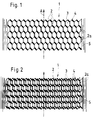
- an elongated film web is shown as a molded part 1 in plan view, which was continuously removed from a roll as winding material.
- perforation-like interfaces are introduced transversely offset in the film running direction A in a known manner by cutting wheels.
- the film strip is still a two-dimensional, flat body.
- the interfaces are now stretched laterally, that is to say transversely to the film running direction, so that hexagonal openings 3 are formed which are delimited by webs 2 and the film web 1 remains connected.
- the hexagonal openings 3 are designed so that the tip 4 points in the film running direction A.
- the side webs 2 stand up during the stretching, so that a three-dimensional body is now formed.
- the edges 5 are wave-shaped, depending on whether toothed belts or chains are used as propulsion. It is essential that the edges 5 experience the same length reduction through the tooth height of the conveyor, which corresponds to the change in length due to the stretching of the film strip.
- the film web 1 which can also be multi-layered as mentioned, rotated at certain intervals in the film running direction or at any angle, can be superimposed.
- the perforation-like interfaces are offset by overlapping ones Cutting wheels are created and these interfaces are stretched in width using a special stretching device without a central web (this creates honeycomb-shaped openings) and then cut into lengths.
- the curling is carried out under a certain pretension.
Landscapes
- Chemical & Material Sciences (AREA)
- Chemical Kinetics & Catalysis (AREA)
- Physics & Mathematics (AREA)
- Thermal Sciences (AREA)
- Organic Chemistry (AREA)
- Engineering & Computer Science (AREA)
- Textile Engineering (AREA)
- Catalysts (AREA)
- Exhaust Gas After Treatment (AREA)
- Physical Or Chemical Processes And Apparatus (AREA)
- Devices And Processes Conducted In The Presence Of Fluids And Solid Particles (AREA)
Abstract
Description
- Die Erfindung betrifft ein flächenartiges Formteil als Füll- oder Trägerkörper für Katalysatoren, Kondensatkörper, Filter od. dgl., mit einer aus einer Vielzahl von Stegen gebildeter, durchgehend wabenförmiger Formkörper, der in einer vorgebbaren Querschnittsfläche, z.B. in einen von einem Medium durchströmten Rohrteil einlegbar ist.
- Es ist bekannt, solchen flächenartige oder gerollte Formteile durch Stanzen oder Prägen herzustellen, wobei vorwiegend oszilierende Maschinenteile eingesetzt werden müssen und kein kontinuierlicher Ablauf der Formbildung gegeben ist. Daher sind solche Einrichtungen zeitaufwendig und unwirtschaftlich.
- Nachteilig ist außerdem, daß bei verschiedenen Anwendungsbereichen jeweils eigene Füllkörper erforderlich sind. So ist beispielsweise bei der katalytischen Reinigung von Abgasen und bei anderen katalytischen Prozessen ein Katalysatorträgerkörper aus Keramik oder abwechselnden Lagen von glatten und gerollten Blechen - gewickelt oder geschichtet - erforderlich. Dadurch ergibt sich eine zurückzulegende Wegstrecke für das Abgas, die starr und geradlinig vorgegeben ist. Das Resultat ist, daß großvolumige Körper erforderlich sind.
- Die sich zeitweilig aufbauenden Gasrückstaudrücke können sich nicht in der vorgegebenen Wegstrecke abbauen. Unerwünschte, erhebliche Druckverluste können hierbei auftreten.
- Ausgehend von diesem Stand der Technik lag der Erfindung die Aufgabe zugrunde, unter anderem einen Katalysatorträgerkörper herzustellen, der insgesamt im Volumen bedeutend geringer als im Vergleich zu den herkömmlichen Volumsgrößen der Katalysatorträgerkörper ist und verbesserte katalytische Umwandlung der Abgase bewerkstelligt. Erfindungsgemäß wird das Ziel dadurch erreicht, daß das Formteil quer oder längs zur Längsachse zu mehreren Lagen zylindrisch oder oval oder ähnlich aufgerollt, oder als ebene Lagen schichtweise sowohl in Längs-, als auch in Querrichtung zu einer Einheit gebildet, verdichtet angeordnet sind und die Stege in beliebigen Winkeln und/oder Ebenen zur Strömungsrichtung liegen, wobei die einzelnen Lagen unter Vorspannung befestigt sind. Dadurcu wird erreicht, daß sowohl laminare, als auch turbulente Strömungen innerhalb des Körpers auftreten, wodurch das Strömungsmedium über eine größere katalytische Oberfläche verfügt.
- Es ist von Vorteil, wenn die Stege einen sechseckig, wabenförmigen Hohlraum umschließen und die Spitze der derart gebildeten Wabe in Längsrichtung weisend das Formteil um diese Achse gerollt ist. Dadurch kann man auch geringe Durchmesser wählen, ohne Knickstellen beim Einrollvorgang befürchten zu müssen.
- Auch ist von Vorteil, wenn das Formteil quer zur Längsachse gerollt ist, und gegebenenfalls zu einem mehrlagigen Gebilde gleicher oder verschiedener Rollrichtung kombiniert ist. Damit wird gewährleistet, daß die katalytische Umwandlung verbessert wird.
- Weiters ist von Vorteil, wenn kleinere Einheiten von Formteilen in Rahmen befestigt und diese austauschbar sind. Hierbei wird eine wechselweise Laufrichtung der Folienbahn ermöglicht und eine gute Vorspannung erzielt.
- Vorteilhaft ist auch, wenn größere Einheiten mit benachbarten Formteilen durch schweißen, löten, kleben oder klemmen der äußeren seitlichen Stege verbunden sind und eine kontinuierliche Einheit bilden. So können auch großvolumige Geräte befüllt werden.
- Ferner ist von Vorteil, wenn das Formteil nach dem Einrollvorgang in Stücke gekappt, zylindrisch eingerollt, an den Enden verdrillt bzw. umgeschlagen, zu zylindrischen Formkörper gewälzt, als Füllkörper dienen. Damit können weitere Anwendungsgebiete, wie Füllkörper für Treibstofftanks od. dgl., erscjlossen werden. Der wesentliche Vorteil ist darin zu sehen, daß die Kohlenwasserstoffe oder dergleichen flüchtige Gase im Tank der natürlichen Verflüchtigung bis zu 60% entzogen werden. Die Verringerung der Algenbildung in Tanks, insbesondere bei Verwendung von Diesel- oder Biokraftstoffen ist somit gegeben.
- Auch ist noch vorteilhaft, wenn die Ränder die gleiche Längenreduzierung durch die Zahnhöhe der Fördereinrichtung erfahren, die der Längenänderung durch die Streckung des Folienbandes zum Formteil entspricht und zu einer Rolle oder Packung wickelbar ist. Damit wird eine saubere ebene Fläche des fertigen Folienbandes erzielt.
- Anhand eines Ausführungsbeispiels sei die Erfindung näher erläutert. Es zeigen:
- Fig. 1 eine einlagige gestreckte Folienbahn
- Fig. 2 mehrlagige Folienbahn.
- In Fig. 1 ist in Draufsicht eine gestreckte Folienbahn als Formteil 1 dargestellt, welches laufend von einer Rolle als Wickelgut entnommen wurde. In gewissen Abständen sind in Folienlaufrichtung A quer versetzt perforationsartige Schnittstellen in bekannter Weise durch Schneidräder eingebracht. In diesem Fertigungsabschnitt ist das Folienband noch ein zweidimensionaler, ebener Körper. Die Schnittstellen werden nun seitlich, also quer zur Folienlaufrichtung, gedehnt, so daß sich sechseckige Öffnungen 3 bilden, die durch Stege 2 begrenzt sind und die Folienbahn 1 verbunden bleibt. Die sechseckigen Öffnungen 3 sind so ausgelegt, daß die Spitze 4 in Folienlaufrichtung A weist. Die seitlichen Stege 2 stellen sich bei der Streckung auf, so daß nun ein dreidimensionaler Körper gebildet ist. Die Ränder 5 sind wellenartig geformt, je nachdem als Vortrieb Zahnriemen oder Ketten verwendet werden. Wesentlich ist, daß die Ränder 5 die gleiche Längenreduzierung durch die Zahnhöhe der Fördereinrichtung erfahren, die der Längenänderung durch die Streckung des Folienbandes entspricht.
- Ausgehend von diesem Formkörper besteht je nach Verwendungszweck die Möglichkeit, die Folienbahn um die Folienlängsrichtung A einzurollen, aber auch quer dazu. Anwendungsgebiete finden sich auch, wenn wie in Fig. 2 aufgeführt, die Folienbahn 1 mehrlagig mit versetzten Öffnungen 3 zu einer Einheit zusammengefaßt sind. Hierbei ist es möglich die Folienbahn 1 mit um die Längsachse A oder quer dazu als weitere Lage zu verwenden.
- Wesentlich ist, daß die Folienbahn 1, die auch wie erwähnt, mehrlagig sein kann, in gewissen Abständen in Folienlaufrichtung quer oder in einem beliebigen Winkel verdreht, übereinandergelagert sein kann. Die perforationsartigen Schnittstellen sind versetzt durch übereinandergreifende Schneidräder erstellt und diese Schnittstellen über eine besondere Streckvorrichtung ohne Mittelsteg in Breite gedehnt (es entstehen wabenförmige Öffnungen) und hernach in Längen geschnitten. Es ist aber auch möglich, die Folienbahn 1 einzurollen, gegebenenfalls mehrlagig, in Stücken zu kappen, zylindrisch einzurollen und an den Enden zu verdrillen bzw. umzuschlagen und zu zylinderförmigen Formkörpern kontinuierlich zu wälzen. Zur optimalen Stabilitätserhaltung erfolgt das Einrollen unter einer gewissen Vorspannung. Weiters ist auch möglich, verschiedene Formen, je nach Anwendungsbereich, z.B. oval, rund, elliptisch oder andere Mischformen herzustellen.
- Durch dieses kontinuierliche Produktionsverfahren wird erreicht, daß die Herstellung wirtschaftlich in großen Mengen möglich ist. Dies ist insofern wichtig, da solche Formteile in so großer Vielzahl einsetzbar sind und der Bedarf sehr groß ist.
Claims (7)
- Flächenartiges Formteil als Füll- oder Trägerkörper für Katalysatoren, Kondensatkörper, Filter od. dgl., mit einer aus einer Vielzahl von Stegen gebildeter, durchgehend wabenförmiger Formkörper, der in einer vorgebbaren Querschnittsfläche, z.B. in einen von einem Medium durchströmten Rohrteil einlegbar ist, dadurch gekennzeichnet, daß das Formteil (1) quer oder längs zur Längsachse (A) zu mehreren Lagen zylindrisch oder oval oder ähnlich aufgerollt, oder als ebene Lagen schichtweise sowohl in Längs-, als auch in Querrichtung zu einer Einheit gebildet, verdichtet angeordnet sind und die Stege (2) in beliebigen Winkeln und/oder Ebenen zur Strömungsrichtung liegen, wobei die einzelnen Lagen unter Vorspannung befestigt sind.
- Flächenartiges Formteil nach Anspruch 1, dadurch gekennzeichnet, daß die Stege (2) einen sechseckig, wabenförmigen Hohlraum (3) umschließen und die Spitze (4) der derart gebildeten Wabe in Längsrichtung weisend das Formteil (1) um diese Achse (A) gerollt ist.
- Flächenartiges Formteil nach Anspruch 1 und 2, dadurch gekennzeichnet, daß das Formteil (1) quer zur Längsachse (A) gerollt ist und gegebenenfalls zu einem mehrlagigen Gebilde gleicher oder verschiedener Rollrichtung kombiniert ist.
- Flächenartiges Formteil nach Anspruch 1 bis 3, dadurch gekennzeichnet, daß kleinere Einheiten von Formteilen (1) in Rahmen befestigt und diese austauschbar sind.
- Flächenartiges Formteil nach Anspruch 1 bis 3, dadurch gekennzeichnet, daß größere Einheiten mit benachbarten Formteilen (1) durch schweißen, löten, kleben oder klemmen der äußeren seitlichen Stege (2a) verbunden sind und eine kontinuierliche Einheit bilden.
- Flächenartiges Formteil nach Anspruch 1 und 2, dadurch gekennzeichnet, daß das Formteil (1) nach dem Einrollvorgang in Stücke gekappt, zylindrisch eingerollt, an den Enden verdrillt bzw. umgeschlagen, zu zylindrischen Formkörper gewälzt, als Füllkörper dienen.
- Flächenartiges Formteil nach Anspruch 1 bis 6, dadurch gekennzeichnet, daß die Ränder (5) die gleiche Längenreduzierung durch die Zahnhöhe der Fördereinrichtung erfahren, die der Längenänderung durch die Streckung des Folienbandes zum Formteil (1) entspricht und zu einer Rolle oder Packung wickelbar ist.
Priority Applications (1)
| Application Number | Priority Date | Filing Date | Title |
|---|---|---|---|
| SI9530421T SI0699474T1 (en) | 1994-09-05 | 1995-09-04 | Sheet-like preform for use as catalyst filling or carrier body, condensation element, filter or the like |
Applications Claiming Priority (3)
| Application Number | Priority Date | Filing Date | Title |
|---|---|---|---|
| AT169294 | 1994-09-05 | ||
| AT1692/94 | 1994-09-05 | ||
| AT0169294A AT402802B (de) | 1994-09-05 | 1994-09-05 | Formteil zur herstellung von trägerkörpern für katalysatoren, kondensatorkörpern, filter od. dgl. |
Publications (3)
| Publication Number | Publication Date |
|---|---|
| EP0699474A2 true EP0699474A2 (de) | 1996-03-06 |
| EP0699474A3 EP0699474A3 (de) | 1996-04-03 |
| EP0699474B1 EP0699474B1 (de) | 2000-04-12 |
Family
ID=3518941
Family Applications (1)
| Application Number | Title | Priority Date | Filing Date |
|---|---|---|---|
| EP95113839A Expired - Lifetime EP0699474B1 (de) | 1994-09-05 | 1995-09-04 | Flächenartiges Formteil als Füll- oder Trägerkörper für Katalysatoren, Kondensatkörper, Filter od.dgl. |
Country Status (7)
| Country | Link |
|---|---|
| US (1) | US5804527A (de) |
| EP (1) | EP0699474B1 (de) |
| AT (1) | AT402802B (de) |
| DE (1) | DE59508164D1 (de) |
| ES (1) | ES2147252T3 (de) |
| GR (1) | GR3033814T3 (de) |
| SI (1) | SI0699474T1 (de) |
Cited By (4)
| Publication number | Priority date | Publication date | Assignee | Title |
|---|---|---|---|---|
| CN1106879C (zh) * | 1998-07-08 | 2003-04-30 | 白连福 | 一种复合螺旋型填料 |
| EP1152844A4 (de) * | 1998-12-24 | 2004-05-06 | Precision Combustion Inc | Struktur für und verfahren zur herstellung aerodynamischen streckmaterial |
| DE102015222972A1 (de) | 2015-11-20 | 2017-05-24 | Robert Bosch Gmbh | Katalysator und Verfahren zur Herstellung |
| CN108771945A (zh) * | 2018-09-18 | 2018-11-09 | 曹峰 | 一种用于废气净化的填料塔 |
Families Citing this family (4)
| Publication number | Priority date | Publication date | Assignee | Title |
|---|---|---|---|---|
| DE10134250A1 (de) * | 2001-07-18 | 2003-01-30 | Behr Gmbh & Co | Desorbierbares Sorptionsfilter, insbesondere für eine Heizungs- oder Klimaanlage eines Kraftfahrzeuges |
| EP1563091B2 (de) * | 2002-10-04 | 2012-06-27 | GE Healthcare Bio-Sciences Corp. | Verfahren und materialien zur verwendung chemischer verbindungen als hilfsmittel zur nukleinsäurelagerung auf medien von nukleinsäurereinigungssystemen |
| CN102091588A (zh) * | 2010-11-10 | 2011-06-15 | 姚光纯 | 液态原料油再分布器 |
| CN105509541A (zh) * | 2016-01-28 | 2016-04-20 | 哈蒙热工环境设备(嘉兴)有限公司 | 一种冷却塔用防堵塞淋水填料 |
Family Cites Families (13)
| Publication number | Priority date | Publication date | Assignee | Title |
|---|---|---|---|---|
| DE1437310U (de) * | 1938-03-24 | 1939-05-23 | ||
| GB607283A (en) * | 1944-03-29 | 1948-08-27 | Francis Leopold Melvill | Improvements in packing for gas or vapour and liquid contacting apparatus |
| US2493726A (en) * | 1947-06-05 | 1950-01-03 | Air Devices Inc | Air filtering media |
| US3218048A (en) * | 1960-09-14 | 1965-11-16 | Gen Cable Corp | Packing for fractionating column and the like |
| DE2226662A1 (de) * | 1972-05-31 | 1972-12-28 | Gould Inc., Cleveland, Ohio (V.St.A.) | Verfahren zur Herstellung von Katalysatoren für die Abgasentgiftung aus Verbrennungskraftmaschinen |
| US3998599A (en) * | 1974-09-20 | 1976-12-21 | Gould Inc. | System for catalytic reduction of NOx emanating from an internal combustion engine |
| US4562015A (en) * | 1984-05-22 | 1985-12-31 | The Munters Corporation | Open mesh fill assembly |
| US4731205A (en) * | 1986-09-08 | 1988-03-15 | Koch Engineering Company, Inc. | Random packing for fluid contact devices and method of preparing said packing |
| JPH0299144A (ja) * | 1988-10-07 | 1990-04-11 | Babcock Hitachi Kk | 板状触媒およびその製法 |
| JPH078328B2 (ja) * | 1988-11-11 | 1995-02-01 | 東洋ダイナム株式会社 | 脱臭装置 |
| JPH04104839A (ja) * | 1990-08-24 | 1992-04-07 | Matsumoto Kokan Kk | 触媒メタル担体とその製造方法 |
| DE4219673A1 (de) * | 1992-06-16 | 1993-12-23 | Emitec Emissionstechnologie | Metallträger aus Streckmetallband |
| JPH06182224A (ja) * | 1992-09-18 | 1994-07-05 | Nippondenso Co Ltd | 自己発熱型ハニカムフィルタ |
-
1994
- 1994-09-05 AT AT0169294A patent/AT402802B/de not_active IP Right Cessation
-
1995
- 1995-09-04 EP EP95113839A patent/EP0699474B1/de not_active Expired - Lifetime
- 1995-09-04 DE DE59508164T patent/DE59508164D1/de not_active Expired - Fee Related
- 1995-09-04 SI SI9530421T patent/SI0699474T1/xx unknown
- 1995-09-04 ES ES95113839T patent/ES2147252T3/es not_active Expired - Lifetime
- 1995-09-05 US US08/523,628 patent/US5804527A/en not_active Expired - Fee Related
-
2000
- 2000-06-29 GR GR20000401513T patent/GR3033814T3/el not_active IP Right Cessation
Non-Patent Citations (1)
| Title |
|---|
| None |
Cited By (4)
| Publication number | Priority date | Publication date | Assignee | Title |
|---|---|---|---|---|
| CN1106879C (zh) * | 1998-07-08 | 2003-04-30 | 白连福 | 一种复合螺旋型填料 |
| EP1152844A4 (de) * | 1998-12-24 | 2004-05-06 | Precision Combustion Inc | Struktur für und verfahren zur herstellung aerodynamischen streckmaterial |
| DE102015222972A1 (de) | 2015-11-20 | 2017-05-24 | Robert Bosch Gmbh | Katalysator und Verfahren zur Herstellung |
| CN108771945A (zh) * | 2018-09-18 | 2018-11-09 | 曹峰 | 一种用于废气净化的填料塔 |
Also Published As
| Publication number | Publication date |
|---|---|
| EP0699474B1 (de) | 2000-04-12 |
| US5804527A (en) | 1998-09-08 |
| GR3033814T3 (en) | 2000-10-31 |
| ES2147252T3 (es) | 2000-09-01 |
| SI0699474T1 (en) | 2000-10-31 |
| EP0699474A3 (de) | 1996-04-03 |
| AT402802B (de) | 1997-09-25 |
| DE59508164D1 (de) | 2000-05-18 |
| ATA169294A (de) | 1997-01-15 |
Similar Documents
| Publication | Publication Date | Title |
|---|---|---|
| EP0737092B1 (de) | Verfahren zur herstellung eines filtereinsatzes | |
| DE3738537C2 (de) | ||
| DE4201791A1 (de) | Flachrohre zum einbau in einen flachrohrwaermetauscher und verfahren zum vereinzeln der flachrohre | |
| DE3744265C2 (de) | Rußfilter zur Abgasreinigung in Kraftfahrzeugen | |
| DE112012000761T5 (de) | Verfahren zum Herstellen eines mehrschichtigen Produkts mit einem Wabenkern | |
| DE19912871A1 (de) | Verfahren und Vorrichtung zum Herstellen eines metallischen Wabenkörpers | |
| DE2452929A1 (de) | Verfahren zum herstellen von wabenkoerpern | |
| DE112012001685T5 (de) | Verfahren zum Herstellen eines mehrschichtigen Produkts mit einem Wabenkern mit verbesserter Festigkeit | |
| EP0671207B1 (de) | Flächiges Struckturelement und daraus gebildete Packung | |
| DE2806538A1 (de) | Verfahren zur herstellung einer kette von tueten | |
| AT402802B (de) | Formteil zur herstellung von trägerkörpern für katalysatoren, kondensatorkörpern, filter od. dgl. | |
| DE4025434A1 (de) | Wabenkoerper mit querschnittsbereichen unterschiedlicher kanalgroessen, insbesondere katalysator-traegerkoerper | |
| DE2805440C2 (de) | Verfahren zum Herstellen von beutelförmigen Behältern und Vorrichtung zur Durchführung des Verfahrens | |
| DE3923094A1 (de) | Katalysator-traegerkoerper | |
| DE19528963A1 (de) | Vorrichtung und Verfahren zur Herstellung eines Wabenkörpers | |
| EP1644620B1 (de) | Verfahren zur herstellung einer metallischen wabenstruktur | |
| DE4221763A1 (de) | Verfahren zum Herstellen eines Katalysators | |
| DE1949823A1 (de) | Filtereinsatz aus gefaltetem Papier | |
| EP0958053B1 (de) | Verfahren und vorrichtung zur herstellung eines wabenkörpers | |
| DE102017205147B4 (de) | Verfahren zur Herstellung eines Wabenkörpers | |
| EP1525378A1 (de) | Metallische lage mit bereichen unterschiedlicher materialdicke, verfahren zur herstellung einer solchen metallischen lage und zumindest teilweise aus solchen metallischen lagen hergestellter wabenk rper | |
| DE102014015907A1 (de) | Vorrichtung und Verfahren zur Herstellung eines Filterbalges eines Flachfilterelements für Fluide sowie ein Flachfilterelement für Fluide mit einem Faltenbalg | |
| DE19601172A1 (de) | Sandwichkernschicht | |
| WO2013178491A1 (de) | Konischer wabenkörper mit schräg radial nach aussen verlaufenden kanälen | |
| DE102006047030A1 (de) | Verfahren zur Herstellung eines schlauchförmigen Filterlelements |
Legal Events
| Date | Code | Title | Description |
|---|---|---|---|
| PUAI | Public reference made under article 153(3) epc to a published international application that has entered the european phase |
Free format text: ORIGINAL CODE: 0009012 |
|
| PUAL | Search report despatched |
Free format text: ORIGINAL CODE: 0009013 |
|
| AK | Designated contracting states |
Kind code of ref document: A2 Designated state(s): CH DE ES FR GB GR IT LI SE |
|
| AX | Request for extension of the european patent |
Free format text: SI PAYMENT 950918 |
|
| RAX | Requested extension states of the european patent have changed |
Free format text: SI PAYMENT 950918 |
|
| AK | Designated contracting states |
Kind code of ref document: A3 Designated state(s): CH DE ES FR GB GR IT LI SE |
|
| AX | Request for extension of the european patent |
Free format text: SI PAYMENT 950918 |
|
| 17P | Request for examination filed |
Effective date: 19960607 |
|
| 17Q | First examination report despatched |
Effective date: 19980707 |
|
| GRAG | Despatch of communication of intention to grant |
Free format text: ORIGINAL CODE: EPIDOS AGRA |
|
| GRAG | Despatch of communication of intention to grant |
Free format text: ORIGINAL CODE: EPIDOS AGRA |
|
| GRAG | Despatch of communication of intention to grant |
Free format text: ORIGINAL CODE: EPIDOS AGRA |
|
| GRAH | Despatch of communication of intention to grant a patent |
Free format text: ORIGINAL CODE: EPIDOS IGRA |
|
| GRAH | Despatch of communication of intention to grant a patent |
Free format text: ORIGINAL CODE: EPIDOS IGRA |
|
| RAP1 | Party data changed (applicant data changed or rights of an application transferred) |
Owner name: EFKON- ENTWICKLUNG FORSCHUNG & KONSTRUKTION VON SO |
|
| RIN1 | Information on inventor provided before grant (corrected) |
Inventor name: RIEDER, HELMUT, DR. Inventor name: STUHLBACHER, FRANZ |
|
| GRAA | (expected) grant |
Free format text: ORIGINAL CODE: 0009210 |
|
| AK | Designated contracting states |
Kind code of ref document: B1 Designated state(s): CH DE ES FR GB GR IT LI SE |
|
| AX | Request for extension of the european patent |
Free format text: SI PAYMENT 19950918 |
|
| REG | Reference to a national code |
Ref country code: CH Ref legal event code: EP |
|
| REF | Corresponds to: |
Ref document number: 59508164 Country of ref document: DE Date of ref document: 20000518 |
|
| REG | Reference to a national code |
Ref country code: CH Ref legal event code: NV Representative=s name: E. BLUM & CO. PATENTANWAELTE |
|
| ITF | It: translation for a ep patent filed | ||
| GBT | Gb: translation of ep patent filed (gb section 77(6)(a)/1977) |
Effective date: 20000623 |
|
| ET | Fr: translation filed | ||
| REG | Reference to a national code |
Ref country code: ES Ref legal event code: FG2A Ref document number: 2147252 Country of ref document: ES Kind code of ref document: T3 |
|
| PLBE | No opposition filed within time limit |
Free format text: ORIGINAL CODE: 0009261 |
|
| STAA | Information on the status of an ep patent application or granted ep patent |
Free format text: STATUS: NO OPPOSITION FILED WITHIN TIME LIMIT |
|
| 26N | No opposition filed | ||
| REG | Reference to a national code |
Ref country code: GB Ref legal event code: IF02 |
|
| REG | Reference to a national code |
Ref country code: SI Ref legal event code: IF |
|
| REG | Reference to a national code |
Ref country code: CH Ref legal event code: PFA Owner name: EFKON- ENTWICKLUNG FORSCHUNG & KONSTRUKTION VON S Free format text: EFKON- ENTWICKLUNG FORSCHUNG & KONSTRUKTION VON SONDERMASCHINEN GES.M.B.H.#ANDRITZER REICHSSTRASSE 66#8045 GRAZ (AT) -TRANSFER TO- EFKON- ENTWICKLUNG FORSCHUNG & KONSTRUKTION VON SONDERMASCHINEN GES.M.B.H.#ANDRITZER REICHSSTRASSE 66#8045 GRAZ (AT) |
|
| PGFP | Annual fee paid to national office [announced via postgrant information from national office to epo] |
Ref country code: CH Payment date: 20080915 Year of fee payment: 14 |
|
| PGFP | Annual fee paid to national office [announced via postgrant information from national office to epo] |
Ref country code: IT Payment date: 20080925 Year of fee payment: 14 Ref country code: FR Payment date: 20080912 Year of fee payment: 14 |
|
| PGFP | Annual fee paid to national office [announced via postgrant information from national office to epo] |
Ref country code: GB Payment date: 20080918 Year of fee payment: 14 |
|
| PGFP | Annual fee paid to national office [announced via postgrant information from national office to epo] |
Ref country code: DE Payment date: 20080919 Year of fee payment: 14 |
|
| PGFP | Annual fee paid to national office [announced via postgrant information from national office to epo] |
Ref country code: SE Payment date: 20080912 Year of fee payment: 14 Ref country code: ES Payment date: 20080929 Year of fee payment: 14 |
|
| PGFP | Annual fee paid to national office [announced via postgrant information from national office to epo] |
Ref country code: GR Payment date: 20080926 Year of fee payment: 14 |
|
| REG | Reference to a national code |
Ref country code: CH Ref legal event code: PL |
|
| EUG | Se: european patent has lapsed | ||
| GBPC | Gb: european patent ceased through non-payment of renewal fee |
Effective date: 20090904 |
|
| REG | Reference to a national code |
Ref country code: FR Ref legal event code: ST Effective date: 20100531 |
|
| REG | Reference to a national code |
Ref country code: SI Ref legal event code: KO00 Effective date: 20100430 |
|
| PG25 | Lapsed in a contracting state [announced via postgrant information from national office to epo] |
Ref country code: FR Free format text: LAPSE BECAUSE OF NON-PAYMENT OF DUE FEES Effective date: 20090930 Ref country code: DE Free format text: LAPSE BECAUSE OF NON-PAYMENT OF DUE FEES Effective date: 20100401 |
|
| PG25 | Lapsed in a contracting state [announced via postgrant information from national office to epo] |
Ref country code: LI Free format text: LAPSE BECAUSE OF NON-PAYMENT OF DUE FEES Effective date: 20090930 Ref country code: GR Free format text: LAPSE BECAUSE OF NON-PAYMENT OF DUE FEES Effective date: 20100406 Ref country code: CH Free format text: LAPSE BECAUSE OF NON-PAYMENT OF DUE FEES Effective date: 20090930 |
|
| PG25 | Lapsed in a contracting state [announced via postgrant information from national office to epo] |
Ref country code: GB Free format text: LAPSE BECAUSE OF NON-PAYMENT OF DUE FEES Effective date: 20090904 |
|
| PG25 | Lapsed in a contracting state [announced via postgrant information from national office to epo] |
Ref country code: IT Free format text: LAPSE BECAUSE OF NON-PAYMENT OF DUE FEES Effective date: 20090904 |
|
| PG25 | Lapsed in a contracting state [announced via postgrant information from national office to epo] |
Ref country code: SE Free format text: LAPSE BECAUSE OF NON-PAYMENT OF DUE FEES Effective date: 20090905 |
|
| REG | Reference to a national code |
Ref country code: ES Ref legal event code: FD2A Effective date: 20111116 |
|
| PG25 | Lapsed in a contracting state [announced via postgrant information from national office to epo] |
Ref country code: ES Free format text: LAPSE BECAUSE OF NON-PAYMENT OF DUE FEES Effective date: 20090905 |