EP0698997B1 - System for deemphasis and reemphasis of high frequencies in a video signal - Google Patents
System for deemphasis and reemphasis of high frequencies in a video signal Download PDFInfo
- Publication number
- EP0698997B1 EP0698997B1 EP95116314A EP95116314A EP0698997B1 EP 0698997 B1 EP0698997 B1 EP 0698997B1 EP 95116314 A EP95116314 A EP 95116314A EP 95116314 A EP95116314 A EP 95116314A EP 0698997 B1 EP0698997 B1 EP 0698997B1
- Authority
- EP
- European Patent Office
- Prior art keywords
- frequency portion
- high frequency
- luminance signal
- signal
- level
- Prior art date
- Legal status (The legal status is an assumption and is not a legal conclusion. Google has not performed a legal analysis and makes no representation as to the accuracy of the status listed.)
- Expired - Lifetime
Links
Images
Classifications
-
- G—PHYSICS
- G11—INFORMATION STORAGE
- G11B—INFORMATION STORAGE BASED ON RELATIVE MOVEMENT BETWEEN RECORD CARRIER AND TRANSDUCER
- G11B20/00—Signal processing not specific to the method of recording or reproducing; Circuits therefor
- G11B20/02—Analogue recording or reproducing
-
- H—ELECTRICITY
- H04—ELECTRIC COMMUNICATION TECHNIQUE
- H04N—PICTORIAL COMMUNICATION, e.g. TELEVISION
- H04N9/00—Details of colour television systems
- H04N9/79—Processing of colour television signals in connection with recording
- H04N9/797—Processing of colour television signals in connection with recording for recording the signal in a plurality of channels, the bandwidth of each channel being less than the bandwidth of the signal
- H04N9/7976—Processing of colour television signals in connection with recording for recording the signal in a plurality of channels, the bandwidth of each channel being less than the bandwidth of the signal by spectrum folding of the high frequency components of the luminance signal
-
- H—ELECTRICITY
- H04—ELECTRIC COMMUNICATION TECHNIQUE
- H04N—PICTORIAL COMMUNICATION, e.g. TELEVISION
- H04N5/00—Details of television systems
- H04N5/76—Television signal recording
- H04N5/91—Television signal processing therefor
- H04N5/92—Transformation of the television signal for recording, e.g. modulation, frequency changing; Inverse transformation for playback
- H04N5/923—Transformation of the television signal for recording, e.g. modulation, frequency changing; Inverse transformation for playback using preemphasis of the signal before modulation and deemphasis of the signal after demodulation
-
- H—ELECTRICITY
- H04—ELECTRIC COMMUNICATION TECHNIQUE
- H04N—PICTORIAL COMMUNICATION, e.g. TELEVISION
- H04N9/00—Details of colour television systems
- H04N9/79—Processing of colour television signals in connection with recording
- H04N9/80—Transformation of the television signal for recording, e.g. modulation, frequency changing; Inverse transformation for playback
- H04N9/82—Transformation of the television signal for recording, e.g. modulation, frequency changing; Inverse transformation for playback the individual colour picture signal components being recorded simultaneously only
- H04N9/8205—Transformation of the television signal for recording, e.g. modulation, frequency changing; Inverse transformation for playback the individual colour picture signal components being recorded simultaneously only involving the multiplexing of an additional signal and the colour video signal
Definitions
- the present invention relates to systems for deemphasis and reemphasis of high frequencies in a video signal and preferred embodiments of the invention aim to provide systems for transmitting a wide bandwidth luminance signal through a narrow bandwidth channel in a backwards compatible manner.
- VCR video cassette recorder
- Various techniques have been developed to enable the full bandwidth luminance signal to be recorded on the narrowband video tape.
- One of these techniques involves folding a high frequency portion of the luminance signal into an unused part of the low frequency portion of its spectrum, a technique called folding.
- This folded luminance signal is combined with the chrominance component of the video signal, and the combined signal recorded on the video cassette.
- the combined signal contains all the information present in the full bandwidth video signal, but occupies (along with the chrominance signal) a bandwidth no wider than the relatively narrow bandwidth of the standard video tape.
- the previously recorded full bandwidth video signal is subsequently regenerated during playback by separating the chrominance signal from the folded luminance signal, unfolding the folded luminance signal and recombining the chrominance signal with the restored full bandwidth luminance signal.
- VCRs utilizing folding techniques One problem with VCRs utilizing folding techniques is that a video cassette which has been recorded using the folding technique is not backwards compatible with VCRs without the unfolding playback circuitry. That is, a video cassette on which a folded full bandwidth video signal is recorded can not be played-back on a VCR which does not have the unfolding circuitry in the playback path without introducing objectionable artifacts.
- a previous solution to this problem has been to lower the amplitude of the high frequency portion of the luminance signal, before it is folded into the low frequency component, a technique called deemphasis.
- the deemphasized folded luminance signal is separated from the chrominance signal.
- the separated luminance signal is then unfolded, and the amplitude of the high frequency portion is increased to restore it to substantially its original level, a technique called reemphasis.
- the adaptive deemphasis circuit in the above mentioned patent application includes circuitry for detecting the level of the high frequency portion of the luminance signal, and circuitry for variably reducing the level of the high frequency portion in response to the detected signal level. If the level of the high frequency portion of the luminance signal is high, then the level of the high frequency portion is reduced by a maximum amount; if the level is low, then the level is reduced by a minimum amount.
- the adaptive reemphasis circuit in the playback path of the above mentioned patent application performs substantially the inverse operation.
- This adaptive reemphasis circuit includes circuitry for detecting the level of the high frequency portion of the unfolded luminance signal, and circuitry for variably increasing the level of the high frequency portion in response to the detected level. If the level of the high frequency portion of the unfolded luminance signal is relatively high, then the level is boosted by the maximum amount; if the level is relatively low, then the level is boosted by the minimum amount.
- the level of the high frequency portion of the luminance signal is high it is reduced by a maximum amount, and when it is low it is reduced by a minimum amount, the level of the high frequency portion is controlled to always be at about the same level.
- This deemphasized luminance signal is then folded, recorded, played back and unfolded. All of these steps may introduce noise. If the introduced noise changes the detected level of the high frequency portion, then the reemphasis function may not be substantially the inverse of the deemphasis function.
- Reference EP-A-0 379 766 describes a method and apparatus for improving the performance of a bandwidth-degrading video storage or transmission system by folding high frequency luminance spectrum components of a video information into lower-band and mid-band luminance spectrum gaps.
- a corresponding video playback apparatus for a video signal of limited band width comprises a FM demodulator for demodulating the received signal and a luminance unfolding circuit for providing an unfolded luminance signal.
- said separating means comprises:
- said coring circuit further comprises a threshold control input terminal and only passes signals exceeding a threshold which varies in response to a signal at said threshold control input terminal; and said system further comprises a user threshold input terminal coupled to said threshold control input terminal.
- said boosting means comprises a multiplier for multiplying said high frequency portion by said scaling factor, wherein said scaling factor is fixed at a predetermined level.
- said boosting means comprises a multiplier for multiplying said high frequency portion by said scaling factor and a gain adjust input terminal for producing said scaling factor in response to a user input.
- a system having a recording portion for recording a luminance signal on a recording medium and a reproducing portion for playing back said luminance signal from a recording medium, wherein said luminance signal comprises a high frequency portion which is folded back into the low frequency portion, wherein said recording portion comprises:
- said reproducing portion has any of the features mentioned above in relation to the first aspect of the invention.
- said adaptive reducing means comprises:
- said adaptive reducing means comprises:
- said separating means comprises a high pass filter.
- said control signal producing means comprises:
- said separating means comprises: a subtractor for subtracting said high frequency portion from said luminance signal to produce said low frequency portion.
- said scaling means comprises a multiplier for multiplying said high frequency portion by said scaling factor.
- said scaling means further comprises a function circuit, responsive to said control signal, for generating said scaling factor.
- said control signal generator produces a signal K having a value which varies from 0, when the level of said high frequency portion is relatively small to 1/2, when the level of said frequency portion is relatively large, and having intermediate values at intermediate levels of said high frequency portion; and said function circuit produces a scaling factor I-K having a value which varies from 1, when the value of said control signal K is 0, to 1/2, when the value of said control signal is 1/2, and having intermediate values at intermediate values of said control signal K.
- Preferred embodiments of video signal recording systems in accordance with the above principles may be economical to build because of the simple circuitry.
- a predetermined amount of boost for the high frequency portion of the luminance signal may be selected to provide an image which is pleasing to the viewer, causes no noticeable artefacts and provides good noise performance.
- Said separating means preferably comprises: a high pass filter responsive to said reduced level luminance signal to form said high frequency portion; a subtractor for subtracting said high frequency portion from said unfolded luminance signal to form said low frequency portion; and an adder for adding the cored and scaled high frequency portion together with the output of said subtractor for producing the full bandwidth re-emphasised luminance signal.
- said coring circuit further comprises: a threshold control input terminal and only passes signals exceeding a threshold which varies in response to a signal at said threshold control input terminal; and the system further comprises a user threshold input terminal coupled to said threshold control input terminal.
- a transmitting portion for a luminance signal and a reproducing portion for receiving said luminance signal wherein said transmitted luminance signal (Y) comprises a high frequency portion which is folded back into the low frequency portion, wherein:
- Said reproducing portion is preferably in accordance with that of the first aspect of the present invention.
- said adaptive reducing means comprises: means for separating a high frequency portion from said luminance signal; and means responsive to said high frequency portion, for producing said control signal only if the level of said high frequency portion exceeds a predetermined threshold level.
- said adaptive reducing means comprises: means for separating a high frequency portion of said luminance signal from a low frequency portion; means for generating a control signal (K) representative of the level of said high frequency portion; means for scaling said high frequency portion by a scaling factor (1-K) related to said control signal (K); and means for combining said scaled high frequency portion and said low frequency portion to form said reduced level luminance signal.
- Said separating means preferably comprises means a high pass filter.
- Said control signal producing means preferably comprises: a rectifier, responsive to said high frequency portion; a corer coupled to said rectifier, for responding to signals exceeding said threshold level; and a low pass filter, coupled to said corer, for producing said control signal.
- Said separating means may comprise a subtractor for subtracting said high frequency portion from said luminance signal to low frequency portion.
- Said scaling means preferably comprises a multiplier for multiplying said high frequency portion by said scaling factor (1-K).
- said scaling means further comprises a function circuit, responsive to said control (K), for generating said scaling factor (1-K).
- the control generator preferably produces a signal K having a value which varies from 0, when the level of said high frequency portion is relatively small, to 1/2, when the level of said high frequency portion is relatively large, and having intermediate values at intermediate levels of said high frequency portion and said function circuit preferably produces a scaling factor 1-K having a value which varies from 1, when the value of said control signal K is O, to 1/2, when the value of said control signal is 1/2, and having intermediate values at intermediate values of said control signal K.
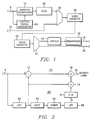
- a luminance signal input terminal 5 is coupled to a source (not shown) of a full bandwidth luminance signal.
- luminance signal input terminal 5 may be coupled to the luminance output terminal of a luminance-chrominance separator in the video signal recording/playback system or to the luminance output terminal of a video camera.
- Luminance signal input terminal 5 is coupled to a signal input terminal of an adaptive deemphasis circuit 10 and an input terminal of a control signal generator 80.
- a control signal output terminal of control signal generator 80 is coupled to a control signal input terminal of the adaptive deemphasis circuit 10.
- An output terminal of the adaptive deemphasis circuit 10 is coupled to an input terminal of a folding circuit 20.
- An output terminal of folding circuit 20 is coupled to a luminance signal input terminal of a combining circuit 30.
- An output terminal of combining circuit 30 is coupled to a mechanism for recording the combined signal on a recording medium.
- the recording mechanism and the medium are made up of well known elements and are represented herein by a video cassette 40.
- a chrominance signal input terminal 25 is coupled to a source (not shown) of a chrominance signal.
- chrominance signal input terminal 25 may be coupled to the chrominance output terminal of the luminance-chrominance separator in the video signal recording/playback system or to the chrominance output terminal of the video camera.
- Chrominance signal input terminal 25 is coupled to a chrominance signal input terminal of combining circuit 30.
- the video cassette 40 also represents known elements making a playback mechanism for retrieving the previously recorded signal from the magnetic medium.
- Video cassette 40 is coupled to an input terminal of a signal separator 50.
- a luminance signal output terminal of signal separator 50 is coupled to an input terminal of an unfolding circuit 60.
- An output terminal of unfolding circuit 60 is coupled to a signal input terminal of a reemphasis circuit 70.
- An output terminal of reemphasis circuit 70 is coupled to luminance signal output terminal 15.
- Luminance signal output terminal 15 is coupled to a utilization means (not shown) for the reconstructed full bandwidth luminance signal from the reemphasis circuit 70.
- the utilization means may, for example, be a luminance-chrominance signal combiner for generating a composite video signal or may be the luminance signal input terminal of a high resolution television monitor.
- a chrominance signal output terminal of separating circuit 50 is coupled to a chrominance signal output terminal 35.
- Chrominance signal output terminal 35 may be coupled to a utilization circuit for the chrominance signal.
- the utilization circuit may be the luminance-chrominance signal combiner for generating a composite video signal or may be the chrominance signal input terminal of the high resolution television monitor.
- control signal generator 80 produces a control signal which represents the level of the high frequency portion of the full bandwidth luminance signal.
- the control signal input is coupled to the control signal output terminal of the adaptive deemphasis circuit 10.
- the adaptive deemphasis circuit 10 operates to variably decrease the level of the high frequency portion of the full bandwidth video signal in response to the control signal from the control signal generator 80.
- the adaptive deemphasis circuit 10 and control signal generator 80 are discussed in detail below.
- the folded deemphasized luminance signal from folding circuit 20 and the chrominance signal from chrominance signal input terminal 25 are combined in a known manner in combining circuit 30.
- the chrominance signal is recorded in a spectral region below the spectral region in which the folded deemphasized luminance signal is recorded and the combined luminance signal and chrominance signal occupies a bandwidth which is less than the bandwidth of the magnetic medium.
- the signal from video cassette 40 is processed by separating circuit 50 in a known manner.
- the chrominance signal is separated from the folded deemphasized luminance signal.
- the played back folded luminance signal is supplied to the unfolding circuit and the chrominance signal is supplied to the chrominance signal output terminal 35.
- Unfolding circuit 60 unfolds the deemphasized high frequency portion of the luminance signal from the low frequency portion, and regenerates the deemphasized full bandwidth luminance signal.
- This unfolded deemphasized full bandwidth luminance signal is supplied to the signal input terminal of the reemphasis circuit 70.
- the reemphasis circuit 70 boosts the high frequency portion of the luminance signal by a predetermined amount.
- the output of the reemphasis circuit 70 is a full bandwidth luminance signal in which the high frequency portion has been restored to substantially the correct level.
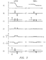
- FIG 2 is a block diagram of an example of an adaptive deemphasis circuit 10 and control signal generator 80 which may be used in the video signal recording/playback system illustrated in Figure 1.
- input terminal 5 corresponds to input terminal 5 of Figure 1.
- Input terminal 5 is coupled to an input terminal of a high pass filter (HPF) 82 and to a minuend input terminal of a subtractor 12.
- An output terminal of subtractor 12 is coupled to an input terminal of an adder 18.
- An output terminal of adder 18 is coupled to an output terminal 45.
- Output terminal 45 is coupled to the input terminal of folding circuit 20 (of Figure 1).
- An output terminal of HPF 82 is coupled to a subtrahend input terminal of subtractor 12, to a first input terminal of a multiplier 16, and to an input terminal of a rectifier 84.
- An output terminal of rectifier 84 is coupled to an input terminal of a corer 86.
- An output terminal of corer 86 is coupled to an input terminal of a low pass filter (LPF) 88.
- An output terminal of LPF 88 produces a control signal K, and is coupled to an input terminal of a 1-K function circuit 14.
- An output terminal of 1-K function circuit 14 is coupled to a second input terminal of multiplier 16.
- An output terminal of multiplier 16 is coupled to a second input terminal of adder 18.
- delay elements will be required at various locations in Figure 2, and will understand where these delay elements should be placed and how long the delay period should be. For clarity, these delay elements are omitted from Figure 2, and will not be discussed in detail below.
- HPF 82 and subtractor 12 separate the high frequency portion from the low frequency portion of the luminance signal.
- the output signal from HPF 82 contains the high frequency portion of the luminance signal.
- the high frequency portion of the luminance signal is subtracted from the full bandwidth luminance signal in subtractor 12, leaving only the low frequency portion.
- the low frequency portion is supplied to adder 18 for combination with an attenuated high frequency portion to form the deemphasized luminance signal.
- the high frequency portion may contain luminance information representing vertical edges.
- Figure 3A illustrates two examples of vertical edges. On the left hand side, a large amplitude vertical edge is illustrated and on the right hand side, a small vertical edge is illustrated.
- Figure 3B illustrates the signal at the output terminal of the HPF 82. This signal is rectified by rectifier 84, and
- Figure 3C illustrates the signal at the output terminal of rectifier 84.
- Corer 86 operates to eliminate the effect of low amplitude edges on the deemphasis function.
- Corer 86 operates as a threshold circuit. If the value of the input signal is less than the threshold value, then a zero valued signal is produced. If the value of the input signal is greater than the threshold value, then the value of the output signal is the value of the input signal less the threshold value.
- Figure 3D illustrates the signal at the output terminal of corer 86. Referring to Figure 3C, the dotted line illustrates the threshold value. In Figure 3D, only the portion of rectified signal illustrated in Figure 3C which exceeds the threshold value passes through the corer circuit 86, producing the signal illustrated in Figure 3D.
- the output signal from corer 86 is passed through LPF 88 to produce control signal K illustrated in Figure 3E.
- the LPF 88 operates to spread the control signal so that it changes gradually in the vicinity of the vertical edge.
- the control signal K is scaled to vary between 0, when the level of the high frequency portion of the luminance signal is small, and 1/2, when the level of the high frequency portion is large.
- the control signal K is then subtracted from the value 1 in the 1-K function circuit 14, producing the signal illustrated in Figure 3F.
- the 1-K function circuit 14 may be constructed in known manner of analog or digital arithmetic elements, or a look-up table, in the case of a digital implementation.
- This signal varies between 1, when the level of the high frequency portion of the luminance signal is small, to 1/2 when the level of the high frequency portion is large.
- This signal is supplied to one input terminal of multiplier 16.
- Multiplier 16 scales the level of the high frequency portion of the luminance signal by multiplying the high frequency portion of the luminance signal by the 1-K signal. This scaled high frequency portion is then added to the low frequency portion of the luminance signal to form the deemphasized luminance signal.
- the scaling factor When the level of the high frequency portion is high, the scaling factor is 1/2 and the level of the high frequency portion is halved. When the level of the high frequency portion is low, the scaling factor is nearly 1 and the level of the high frequency portion is passed through unattenuated. At intermediate levels of the high frequency portion of the luminance signal, the scaling factor is intermediate between 1/2 and 1 and the level of the high frequency portion in the deemphasized luminance signal is at a corresponding intermediate value.
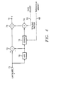
- Figure 4 is a block diagram of the reemphasis circuit 70 illustrated in Figure 1.
- an input terminal 71 is coupled to the output terminal of the unfolding circuit 60 (of Figure 1).
- Input terminal 71 is coupled to a minuend input terminal of a subtractor 72 and to an input terminal of a high pass filter (HPF) 76.
- An output terminal of subtractor 72 is coupled to a first input terminal of adder 74.
- An output terminal of adder 74 is coupled to output terminal 15.
- Output terminal 15 corresponds to the output terminal 15 of Figure 1.
- An output terminal of HPF 76 is coupled to a subtrahend input terminal of subtractor 72 and to an input terminal of corer 73.
- An output terminal of corer 73 is coupled to a first input terminal of multiplier 78.
- a source of a scaling factor is coupled to a second input terminal of multiplier 78.
- HPF 76 and subtractor 72 separate the high frequency portion of the reproduced unfolded deemphasized luminance signal from the low frequency portion.
- the output of the HPF 76 is the high frequency portion, which, when subtracted from the full bandwidth unfolded deemphasized luminance signal in subtractor 72, leaves only the low frequency portion.
- Corer 73 operates as a bidirectional threshold circuit (as opposed to corer 86 (of Figure 2) which operates only in the positive signal direction). If the value of the input signal is closer to zero than a predetermined threshold value, then a zero valued signal is produced. If the value of the input signal is farther from zero than the threshold value, then the value of the output signal is the value of the input signal less the threshold value.
- Figure 3G illustrates the signal at the input terminal of corer 73 and the positive and negative thresholds. In Figure 3G, only the portion of input signal which exceeds the threshold value passes through the corer circuit.
- This coring operation removes low amplitude noise in the high frequency portion resulting from the recording and playback process. Such noise is particularly noticeable in areas of the image where there is no detail.
- This coring operation does not affect the reproduction of the original luminance signal in areas of the image where the level of the high frequency portion was small, because the adaptive deemphasis did not reduce the amplitude of the high frequency portion in these areas. Therefore, the level of the high frequency portion in these areas will tend to remain higher than the noise.
- a user threshold adjust input terminal 65 may be coupled to a threshold input terminal of corer 73, as illustrated in phantom in Figure 4.
- a threshold adjust signal supplied to the threshold adjust input terminal 65, under the control of a user, will adjust the threshold of corer 73. If the threshold is adjusted too low, then noise will appear in areas of the image having no detail; if the threshold is adjusted too high, then only the highest amplitude detail will be provided in the image, and the image may assume a smeared look. The user may adjust the threshold to produce the most pleasing image.
- the cored high frequency portion of the deemphasized luminance signal is scaled by multiplier 78.
- the scale factor is supplied by the scaling factor input terminal of multiplier 78.
- This scaling factor may be fixed at a predetermined level between 1 and 3.
- the scaling factor is fixed at 2.
- a user gain adjust input terminal 55 may be coupled to the scaling factor input terminal of multiplier 78, illustrated in phantom in Figure 4.
- a gain adjust signal, supplied to the gain adjust input terminal 55, under the control of a user, will adjust the scaling factor. As described above, this scaling factor may preferably be varied between 1 and 3 by a user.
- This scaled high frequency portion from multiplier 78 is recombined with the low frequency portion from subtractor 72 in adder 74.
- the output from adder 74 is the full bandwidth reemphasized luminance signal.
- the above signal recording/playback system is described in general terms. It may be implemented in analog form, either in continuous or sampled data form, or may be implemented in digital form. One skilled in the art will understand how to implement this system in any desired form.
Landscapes
- Signal Processing (AREA)
- Engineering & Computer Science (AREA)
- Multimedia (AREA)
- Television Signal Processing For Recording (AREA)
- Picture Signal Circuits (AREA)
- Semiconductor Lasers (AREA)
- Piezo-Electric Transducers For Audible Bands (AREA)
- Processing Of Color Television Signals (AREA)
- Holo Graphy (AREA)
- Television Systems (AREA)
- Diaphragms For Electromechanical Transducers (AREA)
- Details Of Television Scanning (AREA)
- Reduction Or Emphasis Of Bandwidth Of Signals (AREA)
- Developing Agents For Electrophotography (AREA)
Priority Applications (1)
| Application Number | Priority Date | Filing Date | Title |
|---|---|---|---|
| DE9117171U DE9117171U1 (de) | 1990-10-26 | 1991-10-25 | System zum Wiedererzeugen eines Luminanzsignals |
Applications Claiming Priority (3)
| Application Number | Priority Date | Filing Date | Title |
|---|---|---|---|
| US60449390A | 1990-10-26 | 1990-10-26 | |
| US604493 | 1990-10-26 | ||
| EP91309887A EP0482945B1 (en) | 1990-10-26 | 1991-10-25 | De-emphasis and re-emphasis of high frequencies in a video signal |
Related Parent Applications (2)
| Application Number | Title | Priority Date | Filing Date |
|---|---|---|---|
| EP91309887A Division EP0482945B1 (en) | 1990-10-26 | 1991-10-25 | De-emphasis and re-emphasis of high frequencies in a video signal |
| EP91309887.7 Division | 1991-10-25 |
Publications (3)
| Publication Number | Publication Date |
|---|---|
| EP0698997A2 EP0698997A2 (en) | 1996-02-28 |
| EP0698997A3 EP0698997A3 (enExample) | 1996-03-13 |
| EP0698997B1 true EP0698997B1 (en) | 2000-05-10 |
Family
ID=24419822
Family Applications (2)
| Application Number | Title | Priority Date | Filing Date |
|---|---|---|---|
| EP95116314A Expired - Lifetime EP0698997B1 (en) | 1990-10-26 | 1991-10-25 | System for deemphasis and reemphasis of high frequencies in a video signal |
| EP91309887A Expired - Lifetime EP0482945B1 (en) | 1990-10-26 | 1991-10-25 | De-emphasis and re-emphasis of high frequencies in a video signal |
Family Applications After (1)
| Application Number | Title | Priority Date | Filing Date |
|---|---|---|---|
| EP91309887A Expired - Lifetime EP0482945B1 (en) | 1990-10-26 | 1991-10-25 | De-emphasis and re-emphasis of high frequencies in a video signal |
Country Status (11)
| Country | Link |
|---|---|
| EP (2) | EP0698997B1 (enExample) |
| JP (1) | JP2672422B2 (enExample) |
| KR (1) | KR940001422B1 (enExample) |
| CN (1) | CN1030956C (enExample) |
| AT (2) | ATE138522T1 (enExample) |
| CA (1) | CA2053966C (enExample) |
| DE (3) | DE69119693T2 (enExample) |
| DK (1) | DK0482945T3 (enExample) |
| ES (1) | ES2089150T3 (enExample) |
| PT (1) | PT99332A (enExample) |
| TW (1) | TW242212B (enExample) |
Families Citing this family (1)
| Publication number | Priority date | Publication date | Assignee | Title |
|---|---|---|---|---|
| KR930010356B1 (ko) * | 1991-06-27 | 1993-10-16 | 삼성전자 주식회사 | 동적응재생회로 |
Family Cites Families (6)
| Publication number | Priority date | Publication date | Assignee | Title |
|---|---|---|---|---|
| DE1230467B (de) * | 1960-12-19 | 1966-12-15 | Minnesota Mining & Mfg | Einrichtung zur Verbesserung des Verhaeltnisses von Signalspannung zu Rauschspannung bei der UEbertragung oder magnetischen Speicherung von elektrischen Signalen |
| JPS5551938A (en) * | 1978-10-06 | 1980-04-16 | Nissan Motor Co Ltd | Exhaust gas refluxing device for internal combustion engine |
| JPS55117712A (en) * | 1979-02-28 | 1980-09-10 | Matsushita Electric Ind Co Ltd | Noise reduction circuit of video signal recording and reproducing device |
| JPS60152646A (ja) * | 1984-01-23 | 1985-08-10 | Kobe Steel Ltd | 半導体用リ−ドフレ−ム材 |
| JPS6236991A (ja) * | 1985-08-12 | 1987-02-17 | Hitachi Ltd | クリツプ補償回路 |
| US4831463A (en) * | 1987-01-30 | 1989-05-16 | Faroudja Y C | Video processing in which high frequency luminance components are folded into a mid-band spectrum |
-
1991
- 1991-02-28 KR KR1019910003385A patent/KR940001422B1/ko not_active Expired - Fee Related
- 1991-10-05 TW TW080107866A patent/TW242212B/zh active
- 1991-10-18 JP JP3271021A patent/JP2672422B2/ja not_active Expired - Fee Related
- 1991-10-22 CA CA002053966A patent/CA2053966C/en not_active Expired - Fee Related
- 1991-10-25 AT AT91309887T patent/ATE138522T1/de not_active IP Right Cessation
- 1991-10-25 DE DE69119693T patent/DE69119693T2/de not_active Expired - Fee Related
- 1991-10-25 EP EP95116314A patent/EP0698997B1/en not_active Expired - Lifetime
- 1991-10-25 DE DE69132194T patent/DE69132194T2/de not_active Expired - Lifetime
- 1991-10-25 DE DE9117171U patent/DE9117171U1/de not_active Expired - Lifetime
- 1991-10-25 DK DK91309887.7T patent/DK0482945T3/da active
- 1991-10-25 AT AT95116314T patent/ATE192888T1/de not_active IP Right Cessation
- 1991-10-25 ES ES91309887T patent/ES2089150T3/es not_active Expired - Lifetime
- 1991-10-25 EP EP91309887A patent/EP0482945B1/en not_active Expired - Lifetime
- 1991-10-25 PT PT99332A patent/PT99332A/pt not_active Application Discontinuation
- 1991-10-26 CN CN91108373A patent/CN1030956C/zh not_active Expired - Fee Related
Also Published As
| Publication number | Publication date |
|---|---|
| KR920017069A (ko) | 1992-09-26 |
| KR940001422B1 (ko) | 1994-02-23 |
| DE69132194T2 (de) | 2000-10-05 |
| PT99332A (pt) | 1993-12-31 |
| ES2089150T3 (es) | 1996-10-01 |
| EP0698997A2 (en) | 1996-02-28 |
| ATE138522T1 (de) | 1996-06-15 |
| EP0482945A3 (en) | 1993-03-03 |
| DE69119693D1 (de) | 1996-06-27 |
| CA2053966C (en) | 1997-04-22 |
| DE69119693T2 (de) | 1996-11-28 |
| DE69132194D1 (de) | 2000-06-15 |
| CN1030956C (zh) | 1996-02-07 |
| EP0698997A3 (enExample) | 1996-03-13 |
| DK0482945T3 (da) | 1996-06-24 |
| JPH04284788A (ja) | 1992-10-09 |
| EP0482945A2 (en) | 1992-04-29 |
| JP2672422B2 (ja) | 1997-11-05 |
| CA2053966A1 (en) | 1992-04-27 |
| CN1061125A (zh) | 1992-05-13 |
| TW242212B (enExample) | 1995-03-01 |
| ATE192888T1 (de) | 2000-05-15 |
| DE9117171U1 (de) | 1996-09-12 |
| EP0482945B1 (en) | 1996-05-22 |
Similar Documents
| Publication | Publication Date | Title |
|---|---|---|
| JPH039679B2 (enExample) | ||
| JPS647552B2 (enExample) | ||
| EP0698997B1 (en) | System for deemphasis and reemphasis of high frequencies in a video signal | |
| EP0482666A2 (en) | Adaptive deemphasis and reemphasis of high frequencies in a video signal utilizing a recorded control signal | |
| US5418619A (en) | Apparatus and method for selectively adapting a playback characteristic to meet video performance requirements | |
| JP2608199B2 (ja) | 映像信号記録再生方式間の再生時互換性保持回路 | |
| US5187590A (en) | Luminance signal recording circuit and method for maintaining compatibility in reproducing between different video systems | |
| US6393194B1 (en) | Magnetic recording and reproducing video signal in magnetic tape at video quality selectable from prescribed different qualities | |
| JPH05191776A (ja) | 動適応周波数重ね方法及び回路 | |
| KR940002278B1 (ko) | 영상신호 기록재생방식간의 재생시 호환성 유지회로 | |
| US5371601A (en) | Luminance signal unfolding and reemphasizing circuit | |
| JP2831996B2 (ja) | 信号記録装置 | |
| JP2635647B2 (ja) | 映像信号記録再生装置 | |
| KR930010357B1 (ko) | 폴딩된 신호의 복원에 의한 해상도 향상 방식 및 회로 | |
| JP3381913B2 (ja) | 映像音声信号記録装置 | |
| GB2280083A (en) | Producing a recorded luminance signal compatible between different video recording/playback systems | |
| KR100226564B1 (ko) | 입력비디오 신호 재생장치와 비디오 신호기록 및 재생 시스템 | |
| JPS61212985A (ja) | 磁気記録再生装置 | |
| JPH0442683A (ja) | 映像信号記録再生装置 | |
| JPS613594A (ja) | 搬送色信号の記録再生装置 | |
| KR19990053818A (ko) | 화질 보정 장치 | |
| JPH03230371A (ja) | Fm変調輝度信号処理回路 | |
| JPH04357783A (ja) | 磁気記録再生装置 | |
| JPH059993B2 (enExample) | ||
| JPH09154106A (ja) | ディエンファシス回路 |
Legal Events
| Date | Code | Title | Description |
|---|---|---|---|
| PUAI | Public reference made under article 153(3) epc to a published international application that has entered the european phase |
Free format text: ORIGINAL CODE: 0009012 |
|
| PUAL | Search report despatched |
Free format text: ORIGINAL CODE: 0009013 |
|
| 17P | Request for examination filed |
Effective date: 19951114 |
|
| AC | Divisional application: reference to earlier application |
Ref document number: 482945 Country of ref document: EP |
|
| AK | Designated contracting states |
Kind code of ref document: A2 Designated state(s): AT BE DE DK ES FR GB IT NL SE |
|
| AK | Designated contracting states |
Kind code of ref document: A3 Designated state(s): AT BE DE DK ES FR GB IT NL SE |
|
| 17Q | First examination report despatched |
Effective date: 19980629 |
|
| GRAG | Despatch of communication of intention to grant |
Free format text: ORIGINAL CODE: EPIDOS AGRA |
|
| RIC1 | Information provided on ipc code assigned before grant |
Free format text: 6H 04N 5/92 A, 6H 04N 5/922 B |
|
| RTI1 | Title (correction) |
Free format text: SYSTEM FOR DEEMPHASIS AND REEMPHASIS OF HIGH FREQUENCIES IN A VIDEO SIGNAL |
|
| GRAG | Despatch of communication of intention to grant |
Free format text: ORIGINAL CODE: EPIDOS AGRA |
|
| GRAH | Despatch of communication of intention to grant a patent |
Free format text: ORIGINAL CODE: EPIDOS IGRA |
|
| GRAH | Despatch of communication of intention to grant a patent |
Free format text: ORIGINAL CODE: EPIDOS IGRA |
|
| GRAA | (expected) grant |
Free format text: ORIGINAL CODE: 0009210 |
|
| AC | Divisional application: reference to earlier application |
Ref document number: 482945 Country of ref document: EP |
|
| AK | Designated contracting states |
Kind code of ref document: B1 Designated state(s): AT BE DE DK ES FR GB IT NL SE |
|
| PG25 | Lapsed in a contracting state [announced via postgrant information from national office to epo] |
Ref country code: NL Free format text: LAPSE BECAUSE OF FAILURE TO SUBMIT A TRANSLATION OF THE DESCRIPTION OR TO PAY THE FEE WITHIN THE PRESCRIBED TIME-LIMIT Effective date: 20000510 Ref country code: IT Free format text: LAPSE BECAUSE OF FAILURE TO SUBMIT A TRANSLATION OF THE DESCRIPTION OR TO PAY THE FEE WITHIN THE PRESCRIBED TIME-LIMIT;WARNING: LAPSES OF ITALIAN PATENTS WITH EFFECTIVE DATE BEFORE 2007 MAY HAVE OCCURRED AT ANY TIME BEFORE 2007. THE CORRECT EFFECTIVE DATE MAY BE DIFFERENT FROM THE ONE RECORDED. Effective date: 20000510 Ref country code: FR Free format text: LAPSE BECAUSE OF FAILURE TO SUBMIT A TRANSLATION OF THE DESCRIPTION OR TO PAY THE FEE WITHIN THE PRESCRIBED TIME-LIMIT Effective date: 20000510 Ref country code: ES Free format text: THE PATENT HAS BEEN ANNULLED BY A DECISION OF A NATIONAL AUTHORITY Effective date: 20000510 Ref country code: BE Free format text: LAPSE BECAUSE OF FAILURE TO SUBMIT A TRANSLATION OF THE DESCRIPTION OR TO PAY THE FEE WITHIN THE PRESCRIBED TIME-LIMIT Effective date: 20000510 Ref country code: AT Free format text: LAPSE BECAUSE OF FAILURE TO SUBMIT A TRANSLATION OF THE DESCRIPTION OR TO PAY THE FEE WITHIN THE PRESCRIBED TIME-LIMIT Effective date: 20000510 |
|
| REF | Corresponds to: |
Ref document number: 192888 Country of ref document: AT Date of ref document: 20000515 Kind code of ref document: T |
|
| REF | Corresponds to: |
Ref document number: 69132194 Country of ref document: DE Date of ref document: 20000615 |
|
| PG25 | Lapsed in a contracting state [announced via postgrant information from national office to epo] |
Ref country code: SE Free format text: LAPSE BECAUSE OF FAILURE TO SUBMIT A TRANSLATION OF THE DESCRIPTION OR TO PAY THE FEE WITHIN THE PRESCRIBED TIME-LIMIT Effective date: 20000810 Ref country code: DK Free format text: LAPSE BECAUSE OF FAILURE TO SUBMIT A TRANSLATION OF THE DESCRIPTION OR TO PAY THE FEE WITHIN THE PRESCRIBED TIME-LIMIT Effective date: 20000810 |
|
| NLV1 | Nl: lapsed or annulled due to failure to fulfill the requirements of art. 29p and 29m of the patents act | ||
| EN | Fr: translation not filed | ||
| PG25 | Lapsed in a contracting state [announced via postgrant information from national office to epo] |
Ref country code: GB Free format text: LAPSE BECAUSE OF NON-PAYMENT OF DUE FEES Effective date: 20001025 |
|
| PLBE | No opposition filed within time limit |
Free format text: ORIGINAL CODE: 0009261 |
|
| STAA | Information on the status of an ep patent application or granted ep patent |
Free format text: STATUS: NO OPPOSITION FILED WITHIN TIME LIMIT |
|
| 26N | No opposition filed | ||
| GBPC | Gb: european patent ceased through non-payment of renewal fee |
Effective date: 20001025 |
|
| PGFP | Annual fee paid to national office [announced via postgrant information from national office to epo] |
Ref country code: DE Payment date: 20091022 Year of fee payment: 19 |
|
| REG | Reference to a national code |
Ref country code: DE Ref legal event code: R119 Ref document number: 69132194 Country of ref document: DE Effective date: 20110502 |
|
| PG25 | Lapsed in a contracting state [announced via postgrant information from national office to epo] |
Ref country code: DE Free format text: LAPSE BECAUSE OF NON-PAYMENT OF DUE FEES Effective date: 20110502 |