EP0697489B1 - Footfall sound damming supporting element - Google Patents
Footfall sound damming supporting element Download PDFInfo
- Publication number
- EP0697489B1 EP0697489B1 EP95107649A EP95107649A EP0697489B1 EP 0697489 B1 EP0697489 B1 EP 0697489B1 EP 95107649 A EP95107649 A EP 95107649A EP 95107649 A EP95107649 A EP 95107649A EP 0697489 B1 EP0697489 B1 EP 0697489B1
- Authority
- EP
- European Patent Office
- Prior art keywords
- structural element
- container
- receptacle
- screw
- force
- Prior art date
- Legal status (The legal status is an assumption and is not a legal conclusion. Google has not performed a legal analysis and makes no representation as to the accuracy of the status listed.)
- Expired - Lifetime
Links
- 239000000463 material Substances 0.000 claims abstract description 16
- 229920001971 elastomer Polymers 0.000 claims description 25
- 239000000806 elastomer Substances 0.000 claims description 25
- 239000011178 precast concrete Substances 0.000 claims description 4
- 238000006243 chemical reaction Methods 0.000 claims description 2
- 239000004567 concrete Substances 0.000 abstract description 23
- 229910000831 Steel Inorganic materials 0.000 abstract description 5
- 239000010959 steel Substances 0.000 abstract description 5
- 238000009434 installation Methods 0.000 abstract description 3
- 239000004033 plastic Substances 0.000 abstract description 2
- 229920003023 plastic Polymers 0.000 abstract description 2
- 239000002986 polymer concrete Substances 0.000 abstract description 2
- 230000005540 biological transmission Effects 0.000 description 11
- 238000009413 insulation Methods 0.000 description 8
- 238000010276 construction Methods 0.000 description 7
- 238000004519 manufacturing process Methods 0.000 description 5
- 238000009415 formwork Methods 0.000 description 3
- 239000011810 insulating material Substances 0.000 description 3
- 230000002787 reinforcement Effects 0.000 description 3
- 239000004576 sand Substances 0.000 description 3
- 238000009826 distribution Methods 0.000 description 2
- 238000000034 method Methods 0.000 description 2
- 229920000297 Rayon Polymers 0.000 description 1
- 238000001311 chemical methods and process Methods 0.000 description 1
- 238000009792 diffusion process Methods 0.000 description 1
- 230000000694 effects Effects 0.000 description 1
- 230000005284 excitation Effects 0.000 description 1
- 239000000835 fiber Substances 0.000 description 1
- 239000000945 filler Substances 0.000 description 1
- 230000010006 flight Effects 0.000 description 1
- 239000007788 liquid Substances 0.000 description 1
- NJPPVKZQTLUDBO-UHFFFAOYSA-N novaluron Chemical compound C1=C(Cl)C(OC(F)(F)C(OC(F)(F)F)F)=CC=C1NC(=O)NC(=O)C1=C(F)C=CC=C1F NJPPVKZQTLUDBO-UHFFFAOYSA-N 0.000 description 1
- 238000009417 prefabrication Methods 0.000 description 1
- 230000000717 retained effect Effects 0.000 description 1
- 238000003860 storage Methods 0.000 description 1
- 239000000126 substance Substances 0.000 description 1
- 230000007704 transition Effects 0.000 description 1
- 238000009424 underpinning Methods 0.000 description 1
Images
Classifications
-
- E—FIXED CONSTRUCTIONS
- E04—BUILDING
- E04B—GENERAL BUILDING CONSTRUCTIONS; WALLS, e.g. PARTITIONS; ROOFS; FLOORS; CEILINGS; INSULATION OR OTHER PROTECTION OF BUILDINGS
- E04B1/00—Constructions in general; Structures which are not restricted either to walls, e.g. partitions, or floors or ceilings or roofs
- E04B1/62—Insulation or other protection; Elements or use of specified material therefor
- E04B1/74—Heat, sound or noise insulation, absorption, or reflection; Other building methods affording favourable thermal or acoustical conditions, e.g. accumulating of heat within walls
- E04B1/82—Heat, sound or noise insulation, absorption, or reflection; Other building methods affording favourable thermal or acoustical conditions, e.g. accumulating of heat within walls specifically with respect to sound only
- E04B1/84—Sound-absorbing elements
-
- E—FIXED CONSTRUCTIONS
- E04—BUILDING
- E04F—FINISHING WORK ON BUILDINGS, e.g. STAIRS, FLOORS
- E04F11/00—Stairways, ramps, or like structures; Balustrades; Handrails
- E04F11/02—Stairways; Layouts thereof
- E04F11/022—Stairways; Layouts thereof characterised by the supporting structure
-
- E—FIXED CONSTRUCTIONS
- E04—BUILDING
- E04B—GENERAL BUILDING CONSTRUCTIONS; WALLS, e.g. PARTITIONS; ROOFS; FLOORS; CEILINGS; INSULATION OR OTHER PROTECTION OF BUILDINGS
- E04B1/00—Constructions in general; Structures which are not restricted either to walls, e.g. partitions, or floors or ceilings or roofs
- E04B1/62—Insulation or other protection; Elements or use of specified material therefor
- E04B1/74—Heat, sound or noise insulation, absorption, or reflection; Other building methods affording favourable thermal or acoustical conditions, e.g. accumulating of heat within walls
- E04B1/82—Heat, sound or noise insulation, absorption, or reflection; Other building methods affording favourable thermal or acoustical conditions, e.g. accumulating of heat within walls specifically with respect to sound only
- E04B2001/8254—Soundproof supporting of building elements, e.g. stairs, floor slabs or beams, on a structure
Definitions
- the invention relates to a device for impact sound insulation vertical support of a first component, in particular a precast element, on one adjacent second component, with a receptacle in one of the components and with a shear force mandrel, that cooperates with the recording at one end and with its other end towards the other Device protrudes, in the support area between Intake and transverse force mandrel an impact sound absorbing, elastic layer is arranged.
- Such a device is e.g. from the DE-GBM 78 27 042 known. It is used there by one prefabricated stair run made of running boards and side, made of profiled steel under stairs acoustic decoupling on the inner wall of a To house. The shear force mandrel is fixed connected to the steps and the recording is in the house wall as a sleeve with a sound-absorbing lining integrated.
- the production of the stepped fold must therefore be carried out in particular be carried out with high precision as a subsequent adjustment is not possible.
- step folds requires both an additional one in the flight of stairs and on the platform side Stirrup reinforcement.
- the component prepared in this way is used on the construction site with projecting shear force mandrels then with a Crane positioned. At this point they are Stair landings as components on which the stair run should be supported, at least as far as prepared, that on them recordings for those protruding from the stairs Shear force arbors are present.
- the recordings have an elastomer layer on the underside on which the shear force mandrels rest and about the no vibrations between the shear force mandrel and recording can be transferred. So that supports the flight of stairs over the ones in the pictures Shear force mandrels impact sound insulation on the neighboring ones Components.
- a disadvantage of one such device is, on the one hand, that the high accuracy of fit of sleeve and transverse force mandrel a high manufacturing effort presupposes and also that the recordings must be positioned exactly on the stair landing in order to with the shear force mandrels attached to the factory run of the stairs to be able to work together exactly. It is also the exact height of the contact surface of the shear force mandrel crucial in the recording because this affects that the undersides of the stair landing and run stairs without a paragraph can merge.
- An object of the present invention is to achieve this to avoid.
- Another object of the present invention is therefore to provide a device of the type described above which is designed so that at scheduled Overload in a stair-run side provided elastomer layer does not occur can and it is ensured that the impact sound insulation Function of the elastomer layer is not disadvantageous is affected.
- This object is achieved in that the recording arranged in the component to be supported and the transverse force mandrel is locked in the essentially non-rotatable with respect to its horizontal Transverse axis is held in the recording and that the Lock can be canceled.
- the object of this invention has the advantage that it is positioned component to be supported when attaching not only by a supported under this component expensive to set up support must become. Such a support would take the weight of the component to be supported caused vertical forces, so that with you accordingly no inclination as described above Shear force arbors occurred. Instead of such a support under the component are acting as torque supports directly on the shear force mandrel Locks are provided that keep the transverse force mandrel in a horizontal position, until its originally free section is held against rotation.
- This torsion-proof holding of the originally free section is achieved one by, as before, the component, such as. B. the above-mentioned flight of stairs, is lowered with the above shear force mandrels, so that the shear force mandrel in the area of the still to be concreted, supporting Component is located, for. B. on the underpinning of a stair landing supports. This stair landing is then poured out of concrete and then after the concrete that holds the shear force pins on their outside the receiving extending portion has tied is over these sections a twist or tilt of the transverse force mandrel prevented.
- the transverse force mandrel on its original free end with a height adjustment screw to provide for height fixation.
- the component to be supported before concreting the adjacent one Components adjusted or adjusted in height and on the other hand is through the support of the shear force mandrel between the formwork and the lower edge to ensure a distance of the mandrel that at Concreting is filled with concrete so that the mandrel is on its entire circumference is surrounded by concrete. This is for holding the shear force mandrel in the set Concrete necessary.
- the lock in the holder on the part to be supported is advantageously carried out over two in Axial direction of the transverse force mandrel spaced apart from one another, essentially opposite in a vertical plane acting power transmission means. So that will achieved a particularly reliable locking.
- the power transmission means one from the outer surface of the component accessible screw connection.
- a Screwdriver or wrench is on everyone Construction site in place, so that the release of the lock can be done with ordinary tools.
- both power transmission means can formed by appropriate screw connections be.
- the screw connections take over each against the receptacle and against the shear force mandrel support, depending on the arrangement, either compressive forces or but tractive forces.
- One way to access such fittings is to ensure a parallel sleeve-shaped tube extending to the screw axis to be provided by the material surrounding the receptacle of the component runs through. That is, it extends from the screw-in point on the mount to the surface of the component. Through this, therefore a tube forming a channel can then be removed become.
- a power transmission means can be used instead of a screw connection also through a filled container, e.g. be formed in the form of a pressure cell, its power transmission function through physical and / or chemical reactions can be canceled, so the locking repeal.
- this is filler material a gel that pressures through the walls of the Container passes through, in particular diffuses through.
- the pressure required for this results from the Supporting the stair element on the transverse force mandrel.
- the gel comes out of the container relatively is slowly going on, the concrete is in the supporting, the adjacent component fixing the transverse force mandrel hardened long before lifting the container the lock noticeable.
- the essential Advantage of this embodiment is that the Release of the lock takes place automatically and a otherwise the necessary work step is omitted. It can also not happen that when installing the stairway element you forget to release the lock.
- the container can be emptied via diffusion, for example also with a closure that can be opened from the outside be provided. After opening, this occurs Filling material through this closure to the outside, with what the container then loses its function.
- filling material comes in such a case, for example, sand in question, which is well suited to transfer pressure forces, on the other hand also slightly out of the open Can trickle out of the container. But it would also be one Liquid as filling material possible.
- the filling material by other suitable chemical and / or physical processes e.g. Phase transitions, Solution processes, thermal effects, Electro-viscose processes, vibration excitation etc. is released and the container is no longer under pressure can transmit.
- the other power transmission means a counter bearing, in particular made of elastomer. It is but also conceivable for this counter bearing steel or to use similar, because by relieving the burden Power transmission means also the counter bearing Function loses.
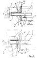
- Figure 1 shows a device for impact sound insulation vertical support of a component.
- the component is, for example, a Stair run 1 to be supported on a stair landing 2 is.
- the staircase 1 is a precast concrete part, that is prefabricated at the factory. In this manufacturing is a sleeve 3 acting as a receptacle in the Poured in concrete, the inside at their top one Has elastomer layer 4.
- the sleeve is made of steel, for example. she can but also from polymer concrete, fiber concrete, plastics or other materials.
- this sleeve 3 is after setting the concrete Stair run 1 used a transverse force mandrel 5, the the elastomer layer 4 rests, the remaining space between the sleeve 3 and the transverse force mandrel 5 by insulating material 6 is filled.
- this soft insulating material 6 on the one hand prevents the transverse force mandrel 5 and the sleeve 3 directly in contact with each other come, it is also achieved that the later Concreting the neighboring component in the concrete Gap between the transverse force mandrel 5 and sleeve 3 flows and possibly forms a rigid sound bridge.
- the transverse force mandrel 5 On his still free end, the transverse force mandrel 5 has an adjusting screw 7 on.
- the transverse force mandrel 5 can both a round as well as a rectangular cross section exhibit.
- the adjusting screw 7, which is shown in FIG. 1 is a hexagon screw, is set so that when lowering the staircase 1 with a Crane the undersides 11 and 12 of the element ceiling 8 or of stairs 1 merge into each other.
- the adjusting screw 7 is supported on a base plate 9 from.
- the dead weight of the stair run 1 tries the transverse force mandrel 5 around the contact point of the adjusting screw 7 to turn counterclockwise. This would but the front edge 13 of the elastomer layer 4 is squeezed and the elastomer layer could then be yours No longer fulfill the function of impact sound insulation. Around To prevent this, the sleeve 3 is locked in the form of a torque support for the transverse force mandrel 5 appropriate.
- This torque-supporting locking is shown in FIG formed by a pressure screw 14 and a counter bearing 15.
- the counter bearing 15 is made of an elastomer material and on the inside of the sleeve 3 below placed.
- the screw 14 runs through a tube 17 which extends from the top 16 of the flight of stairs up to as a recording acting sleeve 3 extends.
- the tube 17 prevents that the screw 14 in the manufacture of the flight of stairs 1 comes into direct contact with concrete and concreted in becomes.
- the screw 14 and the counter bearing 15 are in the axial direction of the transverse force mandrel spaced apart and act in opposite directions as pressure elements. This allows the shear force mandrel to be screwed over a moment can be applied as a support against the inclination mentioned above works. The shear force mandrel is locked in this way.
- the front 19 of the stair case is then suitable Joint material 20 is occupied and then the stair landing 2 is cast from concrete.
- This concrete encloses the free end of the transverse force mandrel 5 completely.
- the screw 14 can be removed become.
- the above-mentioned twisting of the shear force mandrel 5 is then through the set concrete of the stair landing 2 prevented.
- the tube 17 is then e.g. closed with a stopper and on the stairs run 1 becomes a stair covering 21 laid. Finally, the joints between Stair run and stair landing still elastic Joint material 22 closed.
- the mentioned joint material 20 between stairs and Stair landing can be used in addition to the acoustic function also take on the task of shear force in the event of a fire 5 protect from flames and heat. This is but also possible through other design features.
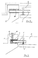
- the transverse force mandrel 5 thus lies on its entire upper surface on the elastomer layer 4 and the counter bearing 23 is relieved of pressure.
- the force of the lag screw 24 in the transverse force mandrel 5 takes place via an inside the transverse force mandrel arranged steel cube 25, in which the lag screw 24 through a hole in the transverse force mandrel 5 is screwed into it. But it is e.g. also possible, through a thread in or on the mandrel the force transmission ensure in the screw.
- the supporting forces of the Tension screw 24 are a wedge 26 in the Concrete of the staircase 1 initiated. Through the oblique Side of this wedge is a good distribution of forces reached. The resulting tensile force is determined by a Reinforcement 30 introduced into the concrete.
- An additional reinforcement 27 can be provided in the transverse force mandrel become.
- FIG. 3 is in place of a pressure screw as in Figure 1 provides a container in the form of a pressure can 28.
- This pressure cell forms together with the counter bearing 23 a torque-supporting lock.
- the pressure can is filled with a gel and has a wall through which the gel under pressure can diffuse outwards. After the stair run element placed on the stair landing this pressure is exerted on the pressure can 28. Diffusing out of the gel contained in the pressure can but goes very slowly, so that the locking of the shear force arbor lasts a long time and only very slowly subsides. Until this state is reached, that is Concrete of the stair landing 2 but already hardened and takes over the anti-rotation of the shear force mandrel 5. Even with such a locking of the mandrel automatically dismantling container is another complete acoustic decoupling of the shear force mandrel possible.
- the container 28 can also For example, be filled with sand, then through pulling a stopper to open a breech can and the sand then e.g. into the inside of the shear force mandrel 5 trickles. The container then loses its ability to transmit pressure and lock is canceled. It is also possible to do this in filling material located in the pressure cell by a dissolve physical and / or chemical process and the container thus its pressure transmission ability to take.
- FIG of the shear force mandrel Another possibility for locking is in FIG of the shear force mandrel.
- a Tension screw 29 becomes the transverse force mandrel 5 in the rear Area of the sleeve 3 up against the elastomer layer 4 biased. This will when you put the Stair run 1 on the element ceiling 8 of the stair landing 2 a the entire surface of the elastomer layer 4 occupying load between shear force 5 and Elastomer layer 4 reached. This load sharing due Prestress is also retained when the concrete of the stair landing 2 is solidified and the transverse force mandrel 5 clamps.
Landscapes
- Physics & Mathematics (AREA)
- Engineering & Computer Science (AREA)
- Architecture (AREA)
- Acoustics & Sound (AREA)
- Civil Engineering (AREA)
- Structural Engineering (AREA)
- Electromagnetism (AREA)
- Manufacturing Of Tubular Articles Or Embedded Moulded Articles (AREA)
- Vibration Dampers (AREA)
- Road Signs Or Road Markings (AREA)
- Sanitary Device For Flush Toilet (AREA)
- Forms Removed On Construction Sites Or Auxiliary Members Thereof (AREA)
Abstract
Description
Die Erfindung betrifft eine Vorrichtung zum trittschalldämmenden vertikalen Abstützen eines ersten Bauelementes, insbesondere eines Betonfertigteils, an einem benachbarten zweiten Bauelement, mit einer Aufnahme in einem der Bauelemente und mit einem Querkraftdorn, der an seinem einen Ende mit der Aufnahme zusammenwirkt und mit seinem anderen Ende in Richtung auf das andere Bauelement vorsteht, wobei im Auflagebereich zwischen Aufnahme und Querkraftdorn eine trittschalldämmende, elastische Schicht angeordnet ist.The invention relates to a device for impact sound insulation vertical support of a first component, in particular a precast element, on one adjacent second component, with a receptacle in one of the components and with a shear force mandrel, that cooperates with the recording at one end and with its other end towards the other Device protrudes, in the support area between Intake and transverse force mandrel an impact sound absorbing, elastic layer is arranged.
Eine solche Vorrichtung ist z.B. aus dem DE-GBM 78 27 042 bekannt. Sie wird dort verwandt, um einen vorgefertigten Treppenlauf aus Trittbrettern und seitlichen, aus Profilstahl gebildeten Treppenzargen unter schalltechnischer Abkopplung an der Innenwand eines Hauses aufzulagern. Der Querkraftdorn ist dabei fest mit den Treppenzargen verbunden und die Aufnahme ist in die Hauswand als Hülse mit trittschalldämmender Auskleidung integriert.Such a device is e.g. from the DE-GBM 78 27 042 known. It is used there by one prefabricated stair run made of running boards and side, made of profiled steel under stairs acoustic decoupling on the inner wall of a To house. The shear force mandrel is fixed connected to the steps and the recording is in the house wall as a sleeve with a sound-absorbing lining integrated.
Bei vorgefertigten Treppenläufen aus Beton wird die Trittschalldämmung bisher üblicherweise über am Treppenlauf und an der Auflagerstelle gegengleich ausgebildete Stufenfalzen erreicht, die durch eine entsprechende trittschalldämmende elastische Schicht getrennt werden. Diese Stufenfalze haben den Nachteil, daß sie einen hohen Schalungsaufwand erfordern, und zwar sowohl bei der fabrikmäßigen Vorfertigung des Treppenlaufes als auch bei der baustellenseitigen Fertigung der Auflagerstelle, die sich z.B. an einem Treppenpodest befindet.For prefabricated stair flights made of concrete, the Impact sound insulation has so far usually been used on stairs and trained counterparts at the bearing point Step folds achieved by an appropriate impact sound-absorbing elastic layer separated become. These step folds have the disadvantage that they require a lot of formwork, both in the factory prefabrication of the staircase as well as in the construction of the support site on site, which e.g. located on a stair landing.
Die Fertigung des Stufenfalzes muß insbesondere deswegen mit hoher Präzision ausgeführt werden, da eine nachträgliche Justiermöglichkeit nicht besteht.The production of the stepped fold must therefore be carried out in particular be carried out with high precision as a subsequent adjustment is not possible.
Außerdem erfordert die Konstruktion der Stufenfalze sowohl im Treppenlauf als auch podestseitig eine zusätzliche Bügelbewehrung.In addition, the construction of the step folds requires both an additional one in the flight of stairs and on the platform side Stirrup reinforcement.
Letztlich besteht bei der zwischen Treppenlauf und Treppenpodest gebildeten Fuge auch die Gefahr, daß sich hier Schmutz, kleine Steinchen etc. festsetzen, die dann eine Schallbrücke bilden.Ultimately, there is between the stairs and Stair pedestal formed joint also the danger that fix dirt, small stones etc. here then form a sound bridge.
Um diese Nachteile zu umgehen, wurde vorgeschlagen, in den Treppenlauf vorstehende Querkraftdorne einzubetonieren, die dann mit entsprechenden Aufnahmen zusammenwirken, die auf der Baustelle in dem abstützenden Bauelement angebracht werden. Dabei läuft der entsprechende Vorschlag darauf hinaus, bei der fabrikmäßigen Fertigung des Treppenlaufes in diesem Betonfertigteil an der zum später benachbarten Bauelement gerichteten Stoßfläche eine Hülse einzubetonieren, die zu der genannten Stoßfläche hin offen ist.To overcome these drawbacks, it has been suggested in to concretize the transverse force mandrels protruding from the stairs, which then work together with corresponding recordings, those on the construction site in the supporting component be attached. The corresponding one runs Suggestion in addition, in the factory production of the flight of stairs in this precast concrete part the one facing the later neighboring component Concreting a sleeve to the abutting surface, to the mentioned Butt surface is open.
Nachdem der Beton des vorgefertigten Betonfertigteils abgebunden hat und die Hülse starr umfängt, wird in die Hülse ein fest_sitzender Querkraftdorn gesteckt, der noch mit etwa einer Hälfte aus der Hülse herausragt.After the concrete of the prefabricated precast concrete has tied and rigidly embraces the sleeve, is in the Sleeve a fixed shear pin inserted still protrudes from the sleeve with about half.
Auf der Baustelle wird das derart vorbereitete Bauelement mit vorstehenden Querkraftdornen dann mit einem Kran in Position gebracht. Zu diesem Zeitpunkt sind die Treppenpodeste als Bauelemente, an denen sich der Treppenlauf abstützen soll, zumindest soweit vorbereitet, daß an ihnen Aufnahmen für die am Treppen lauf vorstehenden Querkraftdorne vorhanden sind. Die Aufnahmen weisen innenliegend auf ihrer Unterseite eine Elastomerschicht auf, auf denen die Querkraftdorne aufliegen und über die keine Schwingungen zwischen Querkraftdorn und Aufnahme übertragen werden können. Damit stützt sich der Treppenlauf über die in den Aufnahmen liegenden Querkraftdorne trittschallgedämmt an den ihm benachbarten Bauelementen ab. Nachteilig bei einer solchen Vorrichtung ist zum einen, daß die hohe Paßgenauigkeit von Hülse und Querkraftdorn einen hohen Fertigungsaufwand voraussetzt und daß außerdem die Aufnahmen am Treppenpodest genau positioniert sein müssen, um mit den werkseitig am Treppen lauf befestigten Querkraftdornen exakt zusammenwirken zu können. Dabei ist auch die exakte Höhe der Auflagefläche des Querkraftdorns in der Aufnahme von entscheidender Bedeutung, da hierüber beeinflußt wird, daß die Unterseiten von Treppenpodest und Treppen lauf ohne einen Absatz aufzuweisen ineinander übergehen können.The component prepared in this way is used on the construction site with projecting shear force mandrels then with a Crane positioned. At this point they are Stair landings as components on which the stair run should be supported, at least as far as prepared, that on them recordings for those protruding from the stairs Shear force arbors are present. The recordings have an elastomer layer on the underside on which the shear force mandrels rest and about the no vibrations between the shear force mandrel and recording can be transferred. So that supports the flight of stairs over the ones in the pictures Shear force mandrels impact sound insulation on the neighboring ones Components. A disadvantage of one such device is, on the one hand, that the high accuracy of fit of sleeve and transverse force mandrel a high manufacturing effort presupposes and also that the recordings must be positioned exactly on the stair landing in order to with the shear force mandrels attached to the factory run of the stairs to be able to work together exactly. It is also the exact height of the contact surface of the shear force mandrel crucial in the recording because this affects that the undersides of the stair landing and run stairs without a paragraph can merge.
Des weiteren muß bei den bisher diskutierten Vorrichtungen die Aufnahme als separates Teil zur Baustelle transportiert werden, um dort schon vorbereitend eingebaut werden zu können. Dies bedeutet einen relativ hohen logistischen Aufwand. Furthermore, in the devices discussed so far the recording as a separate part to the construction site be transported in order to be installed there preparatively to be able to. This means a relative high logistical effort.
Eine Aufgabe der vorliegenden Erfindung ist es, diesen zu vermeiden.An object of the present invention is to achieve this to avoid.
Dabei ist aber ein einfaches Weglassen der Aufnahme auch nicht möglich, da in ihr die trittschalldämmende Schicht angebracht ist. Es ist auch nicht einfach möglich, diese elastomere Schicht in die dann als Aufnahme fungierende, den Querkraftdorn haltende Hülse am Treppenlauf zu übernehmen, da sich damit die Problematik ergäbe, daß die Hülse den Querkraftdorn nicht mehr festsitzend und starr hält. Daraus resultiert zum einen, daß beim Transport des Treppenlaufes zur Einbaustelle der Dorn verlorengehen kann und zum anderen beim Einbau des Treppenlaufes sich der Querkraftdorn aufgrund der herrschenden Kräfte in der Hülse schräg stellen und verkanten würde. Dies führt wiederum dazu, daß die Elastomerschicht in ihrem Randbereich zu stark komprimiert wird und die trittschallentkoppelnde Funktion nicht mehr wahrnehmen kann.But here is a simple omission of the recording not possible either, because it contains the impact sound insulation Layer is attached. It's also not easy to this elastomeric layer in the then as a recording Acting sleeve holding the transverse force mandrel on the stair case to take over, since this raises the problem would result that the sleeve no longer stuck the transverse force mandrel and keeps rigid. On the one hand, this results in that when transporting the flight of stairs to the installation site the thorn can get lost and secondly during installation of the flight of stairs the shear force arbor due to the prevailing forces in the sleeve and would jam. This in turn leads to the Elastomer layer too compressed in its edge area and the impact sound decoupling function can no longer perceive.
Eine weitere Aufgabe der vorliegenden Erfindung ist es daher, eine Vorrichtung der oben beschriebenen Art anzugeben, die so ausgebildet ist, daß bei planmäßiger Belastung eine Überbeanspruchung in einer treppenlaufseitig vorgesehenen Elastomerschicht nicht auftreten kann und dabei sichergestellt ist, daß die trittschalldämmende Funktion der Elastomerschicht nicht nachteilig beeinträchtigt wird.Another object of the present invention is therefore to provide a device of the type described above which is designed so that at scheduled Overload in a stair-run side provided elastomer layer does not occur can and it is ensured that the impact sound insulation Function of the elastomer layer is not disadvantageous is affected.
Diese Aufgabe wird erfindungsgemäß dadurch gelöst, daß die Aufnahme im abzustützenden Bauelement angeordnet ist und der Querkraftdorn über eine Arretierung im wesentlichen verdrehfest bezüglich seiner horizontalen Querachse in der Aufnahme gehalten ist und daß die Arretierung aufhebbar ist. This object is achieved in that the recording arranged in the component to be supported and the transverse force mandrel is locked in the essentially non-rotatable with respect to its horizontal Transverse axis is held in the recording and that the Lock can be canceled.
Es ist zwar aus den Druckschriften CH-A- 376 623, CH-A- 415 999 oder CH-A- 562 968 bekannt, zwei Bauelemente über einen sie verbindenden Dorn zusammenzukoppeln, dabei werden über die Dorne aber auch Längskräfte übertragen. Außerdem sind die Dorne in beiden zu verbindenden Bauelementen starr angeordnet. Eine trittschalldämmende Entkopplung der beiden verbundenen Bauelemente ist aber nicht vorgesehen.Although it is from the publications CH-A- 376 623, CH-A- 415 999 or CH-A- 562 968 known, two components via a mandrel connecting them to couple together, but also longitudinal forces over the mandrels transfer. In addition, the mandrels are in both components to be connected rigidly arranged. A soundproofing decoupling of the two connected components is not provided.
Der Gegenstand dieser Erfindung hat den Vorteil, daß das in Position gebrachte abzustützende Bauelement beim Anbringen nicht erst durch eine unter diesem Bauelement aufwendig einzurichtende Abstützung gehalten werden muß. Eine solche Abstützung nähme die durch das Eigengewicht des abzustützenden Bauelementes bewirkten Vertikalkräfte auf, so daß mit ihr dementsprechend keine wie oben beschriebene Schrägstellung der Querkraftdorne aufträte. Statt einer solchen Abstützung unter dem Bauelement werden direkt am Querkraftdorn als Momentabstützungen fungierende Arretierungen vorgesehen, die den Querkraftdorn in horizontaler Lage halten, bis sein ursprünglich freier Abschnitt verdrehfest gehalten wird.The object of this invention has the advantage that it is positioned component to be supported when attaching not only by a supported under this component expensive to set up support must become. Such a support would take the weight of the component to be supported caused vertical forces, so that with you accordingly no inclination as described above Shear force arbors occurred. Instead of such a support under the component are acting as torque supports directly on the shear force mandrel Locks are provided that keep the transverse force mandrel in a horizontal position, until its originally free section is held against rotation.
Dieses verdrehfeste Halten des ursprünglich freien Abschnittes erreicht man, indem wie bisher das Bauelement, wie z. B. der oben erwähnte Treppenlauf, mit den vorstehenden Querkraftdornen abgesenkt wird, so daß sich der Querkraftdorn im Bereich des noch zu betonierenden, abstützenden Bauelementes befindet, z. B. sich auf der Unterschalung eines Treppenpodestes abstützt. Dieses Treppenpodest wird dann aus Beton gegossen und nachdem dann der Beton, der die Querkraftdorne an deren sich außerhalb der Aufnahme erstreckenden Abschnitt umfängt abgebunden hat, ist über diesen Abschnitte eine Verdrehung bzw. Verkippung des Querkraftdornes verhindert.This torsion-proof holding of the originally free section is achieved one by, as before, the component, such as. B. the above-mentioned flight of stairs, is lowered with the above shear force mandrels, so that the shear force mandrel in the area of the still to be concreted, supporting Component is located, for. B. on the underpinning of a stair landing supports. This stair landing is then poured out of concrete and then after the concrete that holds the shear force pins on their outside the receiving extending portion has tied is over these sections a twist or tilt of the transverse force mandrel prevented.
Dementsprechend kann dann die den Querkraftdorn in der Aufnahme am abzustützenden Teil, d. h. am Treppenlauf haltende Arretierung aufgehoben, bzw. gelöst werden. Ab diesem Zeitpunkt ist dann keine Körperschallübertragung über diese Arretierung mehr möglich und die erwünschte Trittschalldämmung ist voll gewährleistet. Accordingly, the shear force mandrel in the receptacle on part to be supported, d. H. The locking device that stops at the staircase is released, or be solved. From this point on, there is no structure-borne noise transmission more possible with this lock and the desired impact sound insulation is fully guaranteed.
Es ist vorteilhaft, den Querkraftdorn an seinem ursprünglich freien Ende mit einer Höheneinstellschraube zur Höhenfixierung zu versehen. Zum einen kann damit das abzustützende Bauelement vor dem Betonieren der angrenzenden Bauelemente höhenmäßig justiert bzw. angepaßt werden und zum anderen ist durch die Abstützung des Querkraftdornes zwischen Unterschalung und Unterkante des Dornes ein Abstand zu gewährleisten, der beim Betonieren mit Beton gefüllt wird, so daß der Dorn an seinem ganzen Umfang von Beton umgeben ist. Dies ist für das Halten des Querkraftdornes im abgebundenen Beton notwendig.It is advantageous to use the transverse force mandrel on its original free end with a height adjustment screw to provide for height fixation. For one, it can the component to be supported before concreting the adjacent one Components adjusted or adjusted in height and on the other hand is through the support of the shear force mandrel between the formwork and the lower edge to ensure a distance of the mandrel that at Concreting is filled with concrete so that the mandrel is on its entire circumference is surrounded by concrete. This is for holding the shear force mandrel in the set Concrete necessary.
Die Arretierung in der Aufnahme am abzustützenden Teil (Treppenlauf) erfolgt vorteilhafterweise über zwei in Axialrichtung des Querkraftdornes zueinander beabstandete, im wesentlichen in einer Vertikalebene entgegengesetzt wirkende Kraftübertragungsmittel. Damit wird eine besonders funktionssichere Arretierung erreicht.The lock in the holder on the part to be supported (Stair run) is advantageously carried out over two in Axial direction of the transverse force mandrel spaced apart from one another, essentially opposite in a vertical plane acting power transmission means. So that will achieved a particularly reliable locking.
Um die Arretierung aufheben zu können, kann dabei eines der Kraftübertragungsmittel eine von der Außenfläche des Bauelementes zugängliche Verschraubung sein. Ein Schraubendreher oder Schraubenschlüssel ist auf jeder Baustelle vorhanden, so daß das Aufheben der Arretierung mit gewöhnlichem Werkzeug erfolgen kann.To be able to release the lock, one can the power transmission means one from the outer surface of the component accessible screw connection. A Screwdriver or wrench is on everyone Construction site in place, so that the release of the lock can be done with ordinary tools.
Selbstverständlich können auch beide Kraftübertragungsmittel durch entsprechende Verschraubungen gebildet sein. Dabei übernehmen die Verschraubungen, die sich jeweils gegen die Aufnahme und gegen den Querkraftdorn abstützen, je nach Anordnung entweder Druckkräfte oder aber Zugkräfte. Of course, both power transmission means can formed by appropriate screw connections be. The screw connections take over each against the receptacle and against the shear force mandrel support, depending on the arrangement, either compressive forces or but tractive forces.
Eine Möglichkeit, die Zugänglichkeit derartiger Verschraubungen zu gewährleisten, ist, eine sich parallel zur Schraubenachse erstreckende hülsenförmige Röhre vorzusehen, die durch das die Aufnahme umgebende Material des Bauelementes hindurchläuft. D.h., sie erstreckt sich von der Einschraubstelle an der Aufnahme bis zur Oberfläche des Bauelementes. Durch diese somit einen Kanal bildende Röhre kann dann die Schraube entfernt werden.One way to access such fittings is to ensure a parallel sleeve-shaped tube extending to the screw axis to be provided by the material surrounding the receptacle of the component runs through. That is, it extends from the screw-in point on the mount to the surface of the component. Through this, therefore a tube forming a channel can then be removed become.
An Stelle einer Verschraubung kann ein Kraftübertragungsmittel auch durch einen gefüllten Behälter, z.B. in Form einer Druckdose gebildet werden, dessen Kraftübertragungsfunktion durch physikalische und/oder chemische Reaktionen aufhebbar ist, um so die Arretierung aufzuheben.A power transmission means can be used instead of a screw connection also through a filled container, e.g. be formed in the form of a pressure cell, its power transmission function through physical and / or chemical reactions can be canceled, so the locking repeal.
Bei einer bevorzugten Ausführungsform ist dieses Füllmaterial ein Gel, das unter Druck durch die Wände des Behälters hindurchtritt, insbesondere hindurchdiffundiert. Der hierfür notwendige Druck resultiert aus der Auflagerung des Treppenelementes auf dem Querkraftdorn. Da das Heraustreten des Gels aus dem Behälter relativ langsam vor sich geht, ist der Beton im abstützenden, den Querkraftdorn fixierenden benachbarten Bauelement längst erhärtet, bevor sich an dem Behälter die Aufhebung der Arretierung bemerkbar macht. Der wesentliche Vorteil dieser Ausführungsform liegt darin, daß die Aufhebung der Arretierung selbsttätig erfolgt und ein ansonsten notwendiger Arbeitsgang entfällt. So kann es auch nicht vorkommen, daß bei der Montage des Treppenlaufelementes vergessen wird, die Arretierung aufzuheben. In a preferred embodiment, this is filler material a gel that pressures through the walls of the Container passes through, in particular diffuses through. The pressure required for this results from the Supporting the stair element on the transverse force mandrel. As the gel comes out of the container relatively is slowly going on, the concrete is in the supporting, the adjacent component fixing the transverse force mandrel hardened long before lifting the container the lock noticeable. The essential Advantage of this embodiment is that the Release of the lock takes place automatically and a otherwise the necessary work step is omitted. It can also not happen that when installing the stairway element you forget to release the lock.
Anstatt ein Gel vorzusehen, das mit der Zeit den Behälter über Diffussion entleert, kann der Behälter beispielsweise auch mit einem von außen zu öffnenden Verschluß versehen sein. Nach dessen Öffnen tritt dann das Füllmaterial durch diesen Verschluß nach außen, womit der Behälter dann seine Funktion verliert. Als Füllmaterial kommt in einem solchen Fall beispielsweise Sand in Frage, der gut geeignet ist, um Druckkräfte zu übertragen, andererseits aber auch leicht aus dem geöffneten Behälter herausrieseln kann. Es wäre aber auch eine Flüssigkeit als Füllmaterial möglich. Des weiteren ist es denkbar, daß das Füllmaterial durch andere geeignete chemische und/oder physikalische Prozesse z.B. Phasenübergänge, Lösungsprozesse, thermische Einwirkungen, Elektro-Viskose-Vorgänge, Schwingungsanregungen etc. gelöst wird und der Behälter somit keinen Druck mehr übertragen kann.Instead of providing a gel that over time becomes the container The container can be emptied via diffusion, for example also with a closure that can be opened from the outside be provided. After opening, this occurs Filling material through this closure to the outside, with what the container then loses its function. As filling material comes in such a case, for example, sand in question, which is well suited to transfer pressure forces, on the other hand also slightly out of the open Can trickle out of the container. But it would also be one Liquid as filling material possible. Furthermore is it is conceivable that the filling material by other suitable chemical and / or physical processes e.g. Phase transitions, Solution processes, thermal effects, Electro-viscose processes, vibration excitation etc. is released and the container is no longer under pressure can transmit.
Insbesondere bei der Verwendung eines gefüllten Behälters kann das jeweils andere Kraftübertragungsmittel ein Gegenlager insbesondere aus Elastomer sein. Es ist aber auch denkbar, für dieses Gegenlager Stahl oder ähnliches zu verwenden, da durch Entlastung des einen Kraftübertragungsmittels das Gegenlager ebenfalls seine Funktion verliert.Especially when using a filled container can the other power transmission means a counter bearing, in particular made of elastomer. It is but also conceivable for this counter bearing steel or to use similar, because by relieving the burden Power transmission means also the counter bearing Function loses.
Weitere Vorteile und Merkmale der Erfindung ergeben sich aus der nachfolgenden Beschreibung von Ausführungsbeispielen. Dabei zeigt:
- Figur 1
- eine Vorrichtung mit einer Arretierung aus einer Druckschraube und einem Gegenlager aus Elastomer;
Figur 2- eine Vorrichtung mit einer Arretierung aus einer Zugschraube und einem Gegenlager aus Elastomer;
Figur 3- eine Vorrichtung mit einer Arretierung aus einem Behälter und einem Gegenlager aus Elastomer;
Figur 4- eine Vorrichtung mit einer Arretierung mit einer Zugschraube und einem durch die elastomere Schicht gebildeten Gegenlager.
- Figure 1
- a device with a lock of a pressure screw and a counter bearing made of elastomer;
- Figure 2
- a device with a lock of a lag screw and a counter bearing made of elastomer;
- Figure 3
- a device with a lock of a container and a counter bearing made of elastomer;
- Figure 4
- a device with a lock with a lag screw and a counter bearing formed by the elastomeric layer.
Figur 1 zeigt eine Vorrichtung zum trittschalldämmenden
vertikalen Abstützen eines Bauelementes. Bei diesem
Bauelement handelt es sich beispielsweise um einen
Treppenlauf 1 der an einem Treppenpodest 2 aufzulagern
ist. Der Treppenlauf 1 ist dabei ein Betonfertigteil,
das werksmäßig vorgefertigt wird. Bei dieser Fertigung
wird eine als Aufnahme fungierende Hülse 3 mit in den
Beton eingegossen, die innen an ihrer Oberseite eine
Elastomerschicht 4 aufweist.Figure 1 shows a device for impact sound insulation
vertical support of a component. With this
The component is, for example, a
Stair run 1 to be supported on a
Die Hülse besteht beispielsweise aus Stahl. Sie kann aber auch aus Polymerbeton, Faserbeton, Kunststoffen oder anderen Materialien hergestellt werden.The sleeve is made of steel, for example. she can but also from polymer concrete, fiber concrete, plastics or other materials.
In diese Hülse 3 wird nach Abbinden des Betons des
Treppenlaufes 1 ein Querkraftdorn 5 eingesetzt, der an
der Elastomerschicht 4 anliegt, wobei der übrige Raum
zwischen der Hülse 3 und dem Querkraftdorn 5 durch Isoliermaterial
6 gefüllt ist. Durch dieses weiche Isoliermaterial
6 wird zum einen verhindert, daß der Querkraftdorn
5 und die Hülse 3 direkt in Kontakt miteinander
kommen, außerdem wird erreicht, daß beim späteren
Betonieren des benachbarten Bauteiles Beton in den
Spalt zwischen Querkraftdorn 5 und Hülse 3 fließt und
eventuell eine starre Schallbrücke bildet. An seinem
noch freien Ende weist der Querkraftdorn 5 eine Einstellschraube
7 auf. Der Querkraftdorn 5 kann sowohl
einen runden als auch einen rechteckigen Querschnitt
aufweisen.In this
Der mit diesen wesentlichen Merkmalen werksmäßig vorbereitete
Treppenlauf 1 wird zur Baustelle transportiert,
wo der Treppenlauf 1 an einem Treppenpodest 2 aufgelagert
werden soll. Von diesem Treppenpodest existiert
anfänglich nur eine Unterschalung, im hier dargestellten
Fall eine Elementdecke 8. Es ist aber auch möglich,
das Treppenpodest vorzufertigen und nur Aussparungen
zum Ablegen der Querkraftdorne vorzusehen.The one prepared with these essential features at the factory
Stair run 1 is transported to the construction site,
where the stair run 1 is supported on a
Die Einstellschraube 7, bei der es sich in der Figur 1
um eine Sechskantschraube handelt, wird dabei so eingestellt,
daß bei Absenken des Treppenlaufes 1 mit einem
Kran die Unterseiten 11 und 12 der Elementdecke 8 bzw.
des Treppenlaufes 1 bündig ineinander übergehen. Dabei
stützt sich die Einstellschraube 7 auf einer Unterlegplatte
9 ab.The adjusting
Das Eigengewicht des Treppenlaufes 1 versucht den Querkraftdorn
5 um den Aufstandpunkt der Einstellschraube 7
entgegen dem Uhrzeigersinn zu verdrehen. Dadurch würde
aber die Vorderkante 13 der Elastomerschicht 4 gequetscht
und die Elastomerschicht könnte dann ihre
Funktion der Trittschalldämmung nicht mehr erfüllen. Um
dies zu verhindern ist an die Hülse 3 eine Arretierung
in Form einer Momentabstützung für den Querkraftdorn 5
angebracht. The dead weight of the stair run 1 tries the
In der Figur 1 wird diese momentabstützende Arretierung
durch eine Druckschraube 14 und ein Gegenlager 15 gebildet.
Das Gegenlager 15 ist aus einem Elastomermaterial
und auf die unten liegende Innenseite der Hülse 3
gelegt.This torque-supporting locking is shown in FIG
formed by a pressure screw 14 and a
Die Schraube 14 läuft durch eine Röhre 17, die sich von
der Oberseite 16 des Treppenlaufes bis zur als Aufnahme
fungierenden Hülse 3 erstreckt. Die Röhre 17 verhindert,
daß die Schraube 14 bei der Herstellung des Treppenlaufes
1 direkt mit Beton in Kontakt kommt und einbetoniert
wird.The screw 14 runs through a
Die Schraube 14 und das Gegenlager 15 sind in Axialrichtung des Querkraftdornes zueinander beabstandet und wirken in entgegengesetzte Richtungen als Druckelemente. Damit kann über die Schraube auf den Querkraftdorn ein Moment aufgebracht werden, das als Abstützung gegen die oben erwähnte Schrägstellung wirkt. Der Querkraftdorn wird so arretiert.The screw 14 and the counter bearing 15 are in the axial direction of the transverse force mandrel spaced apart and act in opposite directions as pressure elements. This allows the shear force mandrel to be screwed over a moment can be applied as a support against the inclination mentioned above works. The shear force mandrel is locked in this way.
Die Vorderseite 19 des Treppenlaufes wird dann mit geeignetem
Fugenmaterial 20 belegt und anschließend wird
das Treppenpodest 2 aus Beton gegossen. Dieser Beton
umschließt dabei das freie Ende des Querkraftdornes 5
völlig. Sobald dieser Beton abgebunden hat und den
Querkraftdorn 5 starr hält, kann die Schraube 14 entfernt
werden. Das oben erwähnte Verdrehen des Querkraftdornes
5 wird dann durch den abgebundenen Beton
des Treppenpodestes 2 verhindert.The front 19 of the stair case is then suitable
Joint material 20 is occupied and then
the
Nachdem die Schraube 14 entfernt ist, ist die gesamte Berührungsfläche zwischen dem Treppenlauf und dem Treppenpodest durch Elastomer- oder Isoliermaterial getrennt, so daß keine Schallbrücke mehr vorhanden ist und die beiden Bauelemente trittschallmäßig voneinander losgekoppelt sind.After the screw 14 is removed, the whole is Contact area between the stair run and the stair landing separated by elastomer or insulating material, so that there is no sound bridge anymore and the two components impact soundly from each other are disconnected.
Die Röhre 17 wird dann z.B. mit einem Stöpsel verschlossen
und auf den Treppen lauf 1 wird dann Treppenbelag
21 gelegt. Abschließend werden die Fugen zwischen
Treppenlauf und Treppenpodest noch durch elastisches
Fugenmaterial 22 verschlossen.The
Das erwähnte Fugenmaterial 20 zwischen Treppenlauf und
Treppenpodest kann neben der schalltechnischen Funktion
auch die Aufgabe übernehmen, bei einem Brand den Querkraftdorn
5 vor Flammen und Hitze zu schützen. Dies ist
aber auch durch andere konstruktive Merkmale möglich.The mentioned joint material 20 between stairs and
Stair landing can be used in addition to the acoustic function
also take on the task of shear force in the event of a
In der Figur 2 ist anstelle einer von oben wirkenden
Druckschraube wie in Figur 1 eine nach unten wirkende
Zugschraube 24 vorgesehen. Dieser ist wiederum ein Gegenlager
23 zugeordnet, das Druckkräfte aufnimmt.In Figure 2 is instead of one acting from above
Pressure screw as in Figure 1 a downward
Auch bei dem Beispiel nach Figur 2 wird die Einstellschraube
7, die hier als Ringschraube ausgebildet ist,
so eingestellt, daß das über den Querkraftdorn 5 auf
der Elementdecke 8 abgelegte Treppenlaufelement 1 an
seiner Unterseite 11 mit der Unterseite des Treppenlaufes
12 versatzfrei abschließt. Dann wird das Treppenpodest
wie oben beschrieben gegossen und nach Abbinden
des Betons, der dann ein Verdrehen des Querkraftdornes
5 verhindert, die Zugschraube 24 an dem Treppenlauf 1
herausgeschraubt. Damit liegt der Querkraftdorn 5 auf
seiner gesamten oberen Fläche an der Elastomerschicht 4
an und das Gegenlager 23 ist druckentlastet. In the example of Figure 2, the adjusting
Die Krafteinleitung der Zugschraube 24 in den Querkraftdorn
5 erfolgt über einen im Innern des Querkraftdornes
angeordneten Stahlwürfel 25, in den die Zugschraube
24 durch ein Loch am Querkraftdorn 5 hindurch
hineingeschraubt ist. Es ist aber z.B. auch möglich,
durch ein Gewinde im oder am Dorn die Krafteinleitung
in die Schraube sicherzustellen. Die Abstützkräfte der
Zugschraube 24 werden dabei über einen Keil 26 in den
Beton des Treppenlaufes 1 eingeleitet. Durch die schräge
Seite dieses Keiles wird eine gute Kräfteverteilung
erreicht. Die resultierende Zugkraft wird durch eine
Bewehrung 30 in den Beton eingeleitet.The force of the
Zur Sicherstellung der Krafteinleitung vom Treppenlauf
in den Querkraftdorn kann eine Zusatzbewehrung 27 vorgesehen
werden.To ensure the force transmission from the stairs
An
In der Figur 3 ist an Stelle einer Druckschraube wie in
Figur 1 ein Behälter in Form einer Druckdose 28 vorgesehen.
Diese Druckdose bildet zusammen mit dem Gegenlager
23 eine momentabstützende Arretierung. Dabei ist
die Druckdose beispielsweise mit einem Gel gefüllt und
weist eine Wandung auf, durch die das Gel bei Druck
nach außen diffundieren kann. Nachdem das Treppenlaufelement
auf das Treppenpodest abgelegt wird, wird
dieser Druck auf die Druckdose 28 ausgeübt. Das Herausdiffundieren
des in der Druckdose enthaltenen Geles
geht aber sehr langsam vor sich, so daß die Arretierung
des Querkraftdornes lange anhält und erst ganz langsam
nachläßt. Bis dieser Zustand erreicht ist, ist der
Beton des Treppenpodestes 2 aber bereits erhärtet und
übernimmt damit die Verdrehsicherung des Querkraftdornes
5. Auch mit einem solchen die Arretierung des Dornes
selbsttätig abbauenden Behälter ist wieder eine
vollständige schalltechnische Entkopplung des Querkraftdornes
möglich. 3 is in place of a pressure screw as in
Figure 1 provides a container in the form of a pressure can 28.
This pressure cell forms together with the counter bearing
23 a torque-supporting lock. It is
for example, the pressure can is filled with a gel and
has a wall through which the gel under pressure
can diffuse outwards. After the stair run element
placed on the stair landing
this pressure is exerted on the pressure can 28. Diffusing out
of the gel contained in the pressure can
but goes very slowly, so that the locking
of the shear force arbor lasts a long time and only very slowly
subsides. Until this state is reached, that is
Concrete of the stair landing 2 but already hardened and
takes over the anti-rotation of the
Anstatt den Behälter 28 mit Gel zu füllen, kann er auch
beispielsweise mit Sand gefüllt sein, wobei dann durch
das Ziehen eines Stöpsels ein Verschluß geöffnet werden
kann und der Sand dann z.B. in das Innere des Querkraftdornes
5 rieselt. Dabei verliert dann der Behälter
seine Fähigkeit Druck zu übertragen und die Arretierung
ist damit aufgehoben. Außerdem ist es möglich, das in
der Druckdose befindliche Füllmaterial durch einen
physikalischen und/oder chemischen Vorgang aufzulösen
und dem Behälter damit seine Druckübertragungsfähigkeit
zu nehmen.Instead of filling the
In der Figur 4 ist eine weitere Möglichkeit zur Arretierung
des Querkraftdornes dargestellt. Durch eine
Zugschraube 29 wird der Querkraftdorn 5 in dem hinteren
Bereich der Hülse 3 nach oben gegen die Elastomerschicht
4 vorgespannt. Dadurch wird beim Ablegen des
Treppenlaufes 1 auf der Elementdecke 8 des Treppenpodestes
2 eine die gesamte Fläche der Elastomerschicht 4
belegende Belastung zwischen Querkraftdorn 5 und
Elastomerschicht 4 erreicht. Diese Lastverteilung aufgrund
Vorspannung bleibt auch erhalten, wenn der Beton
des Treppenpodestes 2 erstarrt ist und den Querkraftdorn
5 einspannt. Deswegen kann dann die Zugschraube 29
entfernt werden, ohne daß sich die Lastverteilung zwischen
Querkraftdorn 5 und Elastomerschicht 4 wesentlich
verändert und die Belastung der Elastomerschicht bleibt
somit über die gesamte Fläche gleichmäßig. Eine unzulässige
Quetschung der Elastomerschicht tritt nicht
mehr auf. Damit ist auch so eine Möglichkeit gegeben,
eine aufhebbare Momentabstützung zu erreichen.Another possibility for locking is in FIG
of the shear force mandrel. By a
Claims (12)
- Device for the impact sound-attenuating vertical support of a first structural element (1), in particular of a precast concrete part, at an adjacent second structural element (2), with a receptacle (3) in one of the structural elements and with a shear force pin (5) which co-operates at one end with the receptacle (3) and projects with its other end in the direction of the other structural element (2), wherein an impact sound-attentenuating, resilient layer (4) is disposed in the bearing region between the receptacle (3) and the sheer force pin (5), characterised in that
the receptacle (3) is disposed in the structural element (1) which is to be supported and the shear force pin (5) is held by means of a locking mechanism (14, 15, 23, 24, 28, 29) in the receptacle (3) in a substantially rotationally fast manner with respect to its horizontal transverse axis, and that the locking mechanism is releasable. - Device according to claim 1,
characterised in that the locking mechanism comprises two force-transmitting means (14, 15; 23, 24; 23, 28) which are spaced apart in the axial direction of the sheer force pin and act substantially in opposite directions in a vertical plane. - Device according to claim 2,
characterised in that at least one of the force-transmitting means (14, 24, 29) is a screw fitting which is accessible from the external surface (16, 11) of the structural element (1). - Device according to claim 3,
characterised in that the screw fitting (14) absorbs compressive forces. - Device acccrding to claim 3,
characterised in that the screw fitting (24, 29) absorbs tensile forces. - Device according to claim 3,
characterised in that the accessibility of the screw fitting (14, 24, 29) is guaranteed by a tube (17) extending parallel to the screw axis through the material of the structural element (1) which surrounds the receptacle (3). - Device according to claim 2,
characterised in that at least one of the force-transmitting means is a filled container (28), the force-transmitting function of which can be terminated by physical and/or chemical reactions. - Device according to claim 7,
characterised in that the container contains a filling material which passes through the walls of the container under pressure. - Device according to claim 7,
characterised in that the container can be emptied by means of a closure which can be opened from outside. - Device according to claim 7,
characterised in that a means which dissolves the container, the filling material or parts thereof and thus terminates the function of the container can be introduced into or is already contained in the latter. - Device according to claim 2,
characterised in that one of the force-transmitting means is an abutment (23), consisting in particular of an elastomer. - Device according to claim 1,
characterised in that the shear force pin comprises at its free end a vertical adjustment means, in particular a screw (7), for the structural element (1).
Applications Claiming Priority (2)
| Application Number | Priority Date | Filing Date | Title |
|---|---|---|---|
| DE4429605A DE4429605A1 (en) | 1994-08-20 | 1994-08-20 | Impact sound absorbing support element |
| DE4429605 | 1994-08-20 |
Publications (2)
| Publication Number | Publication Date |
|---|---|
| EP0697489A1 EP0697489A1 (en) | 1996-02-21 |
| EP0697489B1 true EP0697489B1 (en) | 1999-04-07 |
Family
ID=6526193
Family Applications (1)
| Application Number | Title | Priority Date | Filing Date |
|---|---|---|---|
| EP95107649A Expired - Lifetime EP0697489B1 (en) | 1994-08-20 | 1995-05-19 | Footfall sound damming supporting element |
Country Status (3)
| Country | Link |
|---|---|
| EP (1) | EP0697489B1 (en) |
| AT (1) | ATE178682T1 (en) |
| DE (2) | DE4429605A1 (en) |
Families Citing this family (7)
| Publication number | Priority date | Publication date | Assignee | Title |
|---|---|---|---|---|
| CH688383A5 (en) * | 1994-12-12 | 1997-08-29 | Egco Ag | Transverse load mandrel support. |
| DE29504707U1 (en) * | 1995-03-24 | 1995-05-04 | Schöck Bauteile GmbH, 76534 Baden-Baden | Joint plate |
| DE19602306B4 (en) * | 1996-01-23 | 2004-02-19 | Schöck Entwicklungsgesellschaft mbH | carrying device |
| ATE307939T1 (en) * | 1996-06-27 | 2005-11-15 | Hm Betonfertigteilwerk Hans Ma | SUPPORT FOR A PREFABRICATED CONCRETE STAIRCASE |
| DE202005008862U1 (en) * | 2005-06-07 | 2005-08-11 | Schöck Bauteile GmbH | Step constructional component of concrete has first sound insulating elements for force-transmitting support of step component on adjacent structure, and second elements for sound insulated spacing from adjacent structure |
| DE102011009762A1 (en) * | 2011-01-28 | 2012-08-02 | Schöck Bauteile GmbH | Component for installation in joints of buildings |
| DE102012002168A1 (en) * | 2012-02-07 | 2013-08-08 | Schöck Bauteile GmbH | Component for installation in joints of buildings |
Citations (2)
| Publication number | Priority date | Publication date | Assignee | Title |
|---|---|---|---|---|
| CH376623A (en) * | 1959-11-23 | 1964-04-15 | Schmid Peter | Frame made of profile pieces that are at least partially detachably and adjustably connected to one another |
| CH415999A (en) * | 1964-05-11 | 1966-06-30 | Straessle Marcel | Frame with at least one profiled rod |
Family Cites Families (8)
| Publication number | Priority date | Publication date | Assignee | Title |
|---|---|---|---|---|
| DD98967A1 (en) * | 1972-07-06 | 1973-07-12 | ||
| CH562968A5 (en) * | 1973-03-01 | 1975-06-13 | Syma Intercontinental Sa | Coupling device for walls and frame components - has anchor with conical end enclosed in expanding ring |
| DD128548B1 (en) * | 1976-11-09 | 1980-01-30 | Rudolf Dietz | DEVICE FOR ASSEMBLING AND MOUNTING FLAECHENFOERMIGER COMPONENTS |
| DE7827042U1 (en) | 1978-09-12 | 1978-12-21 | Georg Jaeger & Sohn Kg, 6310 Gruenberg | INTERIOR STAIRS, IN PARTICULAR FOR TERRACED HOUSES |
| DE3408556A1 (en) * | 1984-03-08 | 1985-09-12 | Eberhard Ing.(grad.) 7570 Baden-Baden Schöck | Separating element for concrete slabs |
| DE8702129U1 (en) * | 1987-02-12 | 1987-04-16 | Udo Fuchs GmbH, 7968 Saulgau | Elastic sleeve for sound insulation in prefabricated stairs |
| DE4002661A1 (en) * | 1990-01-30 | 1991-08-01 | Schoeck Bauteile Gmbh | Vertical load transmitting bracket - comprises insulating layer in moulding built into wall |
| ATE133224T1 (en) * | 1991-11-29 | 1996-02-15 | Toni H Erb | SHEARING MANDLE CONNECTION ARRANGEMENT |
-
1994
- 1994-08-20 DE DE4429605A patent/DE4429605A1/en not_active Withdrawn
-
1995
- 1995-05-19 DE DE59505565T patent/DE59505565D1/en not_active Expired - Fee Related
- 1995-05-19 EP EP95107649A patent/EP0697489B1/en not_active Expired - Lifetime
- 1995-05-19 AT AT95107649T patent/ATE178682T1/en not_active IP Right Cessation
Patent Citations (2)
| Publication number | Priority date | Publication date | Assignee | Title |
|---|---|---|---|---|
| CH376623A (en) * | 1959-11-23 | 1964-04-15 | Schmid Peter | Frame made of profile pieces that are at least partially detachably and adjustably connected to one another |
| CH415999A (en) * | 1964-05-11 | 1966-06-30 | Straessle Marcel | Frame with at least one profiled rod |
Also Published As
| Publication number | Publication date |
|---|---|
| DE59505565D1 (en) | 1999-05-12 |
| EP0697489A1 (en) | 1996-02-21 |
| ATE178682T1 (en) | 1999-04-15 |
| DE4429605A1 (en) | 1996-02-22 |
Similar Documents
| Publication | Publication Date | Title |
|---|---|---|
| DE68901920T2 (en) | ELEVATOR SHAFT. | |
| EP3112542B1 (en) | Device and method for heat decoupling of concreted parts of buildings | |
| EP2914790A1 (en) | Method for producing a tower construction from reinforced concrete | |
| EP2715013B1 (en) | Connecting arrangement and method for producing a punching shear reinforcement, a subsequent lateral-force reinforcement and/or a reinforcement connection | |
| EP0433224A1 (en) | Composite support element | |
| EP2610410A2 (en) | Construction element for heat insulation | |
| EP0697489B1 (en) | Footfall sound damming supporting element | |
| DE19501277C2 (en) | Precast balcony | |
| EP3161226B1 (en) | Anchor dowel | |
| EP1860246B1 (en) | Building element for heat insulation | |
| DE19630552C2 (en) | Component for thermal insulation | |
| DE19639576A1 (en) | Fixing for column of swivel crane | |
| DE29917220U1 (en) | Mounting bracket system with installation aid | |
| DE1683121A1 (en) | Spiral staircase | |
| DE3302075A1 (en) | Prestressed concrete or reinforced concrete bending support | |
| DE19928757C2 (en) | Mounting bracket system and method for mounting a prefabricated component on a building part | |
| DE20219324U1 (en) | building basement | |
| DE19724393A1 (en) | Wall support fixing for add-on balcony on residential buildings | |
| EP2069581B1 (en) | Reinforced concrete structure for a building, and method for the erection of such a structure | |
| AT523024B1 (en) | Building construction and method of forming same | |
| DE19806164A1 (en) | Bolt for supporting prefabricated concrete part against wall and damping footstep noise | |
| DE20016009U1 (en) | Fastening the column of a jib crane on a concrete foundation | |
| EP3611310A1 (en) | Support corbel | |
| DE7733030U1 (en) | PREFABRICATED ASSEMBLY STAIRS | |
| EP0826845A2 (en) | Device for taking up tension forces |
Legal Events
| Date | Code | Title | Description |
|---|---|---|---|
| PUAI | Public reference made under article 153(3) epc to a published international application that has entered the european phase |
Free format text: ORIGINAL CODE: 0009012 |
|
| AK | Designated contracting states |
Kind code of ref document: A1 Designated state(s): AT BE CH DE DK FR GB IT LI LU NL SE |
|
| 17P | Request for examination filed |
Effective date: 19960122 |
|
| 17Q | First examination report despatched |
Effective date: 19980217 |
|
| GRAG | Despatch of communication of intention to grant |
Free format text: ORIGINAL CODE: EPIDOS AGRA |
|
| GRAG | Despatch of communication of intention to grant |
Free format text: ORIGINAL CODE: EPIDOS AGRA |
|
| GRAH | Despatch of communication of intention to grant a patent |
Free format text: ORIGINAL CODE: EPIDOS IGRA |
|
| GRAH | Despatch of communication of intention to grant a patent |
Free format text: ORIGINAL CODE: EPIDOS IGRA |
|
| GRAA | (expected) grant |
Free format text: ORIGINAL CODE: 0009210 |
|
| AK | Designated contracting states |
Kind code of ref document: B1 Designated state(s): AT BE CH DE DK FR GB IT LI LU NL SE |
|
| PG25 | Lapsed in a contracting state [announced via postgrant information from national office to epo] |
Ref country code: SE Free format text: THE PATENT HAS BEEN ANNULLED BY A DECISION OF A NATIONAL AUTHORITY Effective date: 19990407 Ref country code: NL Free format text: LAPSE BECAUSE OF FAILURE TO SUBMIT A TRANSLATION OF THE DESCRIPTION OR TO PAY THE FEE WITHIN THE PRESCRIBED TIME-LIMIT Effective date: 19990407 Ref country code: IT Free format text: LAPSE BECAUSE OF FAILURE TO SUBMIT A TRANSLATION OF THE DESCRIPTION OR TO PAY THE FEE WITHIN THE PRE;WARNING: LAPSES OF ITALIAN PATENTS WITH EFFECTIVE DATE BEFORE 2007 MAY HAVE OCCURRED AT ANY TIME BEFORE 2007. THE CORRECT EFFECTIVE DATE MAY BE DIFFERENT FROM THE ONE RECORDED.SCRIBED TIME-LIMIT Effective date: 19990407 Ref country code: GB Free format text: LAPSE BECAUSE OF NON-PAYMENT OF DUE FEES Effective date: 19990407 Ref country code: FR Free format text: LAPSE BECAUSE OF FAILURE TO SUBMIT A TRANSLATION OF THE DESCRIPTION OR TO PAY THE FEE WITHIN THE PRESCRIBED TIME-LIMIT Effective date: 19990407 |
|
| REF | Corresponds to: |
Ref document number: 178682 Country of ref document: AT Date of ref document: 19990415 Kind code of ref document: T |
|
| REG | Reference to a national code |
Ref country code: CH Ref legal event code: EP |
|
| REF | Corresponds to: |
Ref document number: 59505565 Country of ref document: DE Date of ref document: 19990512 |
|
| PG25 | Lapsed in a contracting state [announced via postgrant information from national office to epo] |
Ref country code: LU Free format text: LAPSE BECAUSE OF NON-PAYMENT OF DUE FEES Effective date: 19990519 Ref country code: AT Free format text: LAPSE BECAUSE OF NON-PAYMENT OF DUE FEES Effective date: 19990519 |
|
| PG25 | Lapsed in a contracting state [announced via postgrant information from national office to epo] |
Ref country code: LI Free format text: LAPSE BECAUSE OF NON-PAYMENT OF DUE FEES Effective date: 19990531 Ref country code: CH Free format text: LAPSE BECAUSE OF NON-PAYMENT OF DUE FEES Effective date: 19990531 Ref country code: BE Free format text: LAPSE BECAUSE OF NON-PAYMENT OF DUE FEES Effective date: 19990531 |
|
| PG25 | Lapsed in a contracting state [announced via postgrant information from national office to epo] |
Ref country code: DK Free format text: LAPSE BECAUSE OF FAILURE TO SUBMIT A TRANSLATION OF THE DESCRIPTION OR TO PAY THE FEE WITHIN THE PRESCRIBED TIME-LIMIT Effective date: 19990707 |
|
| NLV1 | Nl: lapsed or annulled due to failure to fulfill the requirements of art. 29p and 29m of the patents act | ||
| EN | Fr: translation not filed | ||
| GBV | Gb: ep patent (uk) treated as always having been void in accordance with gb section 77(7)/1977 [no translation filed] |
Effective date: 19990407 |
|
| BERE | Be: lapsed |
Owner name: SCHOCK BAUTEILE G.M.B.H. Effective date: 19990531 |
|
| REG | Reference to a national code |
Ref country code: CH Ref legal event code: PL |
|
| PLBE | No opposition filed within time limit |
Free format text: ORIGINAL CODE: 0009261 |
|
| STAA | Information on the status of an ep patent application or granted ep patent |
Free format text: STATUS: NO OPPOSITION FILED WITHIN TIME LIMIT |
|
| 26N | No opposition filed | ||
| PGFP | Annual fee paid to national office [announced via postgrant information from national office to epo] |
Ref country code: DE Payment date: 20010529 Year of fee payment: 7 |
|
| GBT | Gb: translation of ep patent filed (gb section 77(6)(a)/1977) |
Effective date: 20010712 |
|
| PG25 | Lapsed in a contracting state [announced via postgrant information from national office to epo] |
Ref country code: DE Free format text: LAPSE BECAUSE OF NON-PAYMENT OF DUE FEES Effective date: 20021203 |