EP0695003B1 - Optische Mehrkernfaser mit Dotierung aus seltenen Erden, Herstellungsmethode dafür und optischer Verstärker mit dieser Faser - Google Patents
Optische Mehrkernfaser mit Dotierung aus seltenen Erden, Herstellungsmethode dafür und optischer Verstärker mit dieser Faser Download PDFInfo
- Publication number
- EP0695003B1 EP0695003B1 EP95303954A EP95303954A EP0695003B1 EP 0695003 B1 EP0695003 B1 EP 0695003B1 EP 95303954 A EP95303954 A EP 95303954A EP 95303954 A EP95303954 A EP 95303954A EP 0695003 B1 EP0695003 B1 EP 0695003B1
- Authority
- EP
- European Patent Office
- Prior art keywords
- rare earth
- optical fiber
- core
- earth element
- optical
- Prior art date
- Legal status (The legal status is an assumption and is not a legal conclusion. Google has not performed a legal analysis and makes no representation as to the accuracy of the status listed.)
- Expired - Lifetime
Links
- 239000013307 optical fiber Substances 0.000 title claims description 146
- 229910052761 rare earth metal Inorganic materials 0.000 title claims description 99
- 150000002910 rare earth metals Chemical class 0.000 title claims description 81
- 230000003287 optical effect Effects 0.000 title claims description 74
- 238000000034 method Methods 0.000 title claims description 16
- 230000005284 excitation Effects 0.000 claims description 47
- 238000005253 cladding Methods 0.000 claims description 21
- VYPSYNLAJGMNEJ-UHFFFAOYSA-N Silicium dioxide Chemical compound O=[Si]=O VYPSYNLAJGMNEJ-UHFFFAOYSA-N 0.000 claims description 18
- 229910052691 Erbium Inorganic materials 0.000 claims description 11
- 230000001902 propagating effect Effects 0.000 claims description 11
- 229910052782 aluminium Inorganic materials 0.000 claims description 10
- 229910052769 Ytterbium Inorganic materials 0.000 claims description 9
- 229910052681 coesite Inorganic materials 0.000 claims description 7
- 239000002131 composite material Substances 0.000 claims description 7
- 229910052906 cristobalite Inorganic materials 0.000 claims description 7
- 239000000377 silicon dioxide Substances 0.000 claims description 7
- 229910052682 stishovite Inorganic materials 0.000 claims description 7
- 229910052905 tridymite Inorganic materials 0.000 claims description 7
- 238000010438 heat treatment Methods 0.000 claims description 6
- 239000011521 glass Substances 0.000 claims description 5
- 229910052779 Neodymium Inorganic materials 0.000 claims description 4
- 230000008878 coupling Effects 0.000 claims description 4
- 238000010168 coupling process Methods 0.000 claims description 4
- 238000005859 coupling reaction Methods 0.000 claims description 4
- 239000000463 material Substances 0.000 claims description 3
- 229910052684 Cerium Inorganic materials 0.000 claims description 2
- 229910052689 Holmium Inorganic materials 0.000 claims description 2
- 229910052772 Samarium Inorganic materials 0.000 claims description 2
- XAGFODPZIPBFFR-UHFFFAOYSA-N aluminium Chemical compound [Al] XAGFODPZIPBFFR-UHFFFAOYSA-N 0.000 description 8
- 230000005540 biological transmission Effects 0.000 description 6
- 238000004519 manufacturing process Methods 0.000 description 4
- 229910052777 Praseodymium Inorganic materials 0.000 description 3
- 238000004891 communication Methods 0.000 description 3
- 238000012986 modification Methods 0.000 description 3
- 230000004048 modification Effects 0.000 description 3
- PNEYBMLMFCGWSK-UHFFFAOYSA-N aluminium oxide Inorganic materials [O-2].[O-2].[O-2].[Al+3].[Al+3] PNEYBMLMFCGWSK-UHFFFAOYSA-N 0.000 description 2
- 230000003321 amplification Effects 0.000 description 2
- 229910052593 corundum Inorganic materials 0.000 description 2
- YBMRDBCBODYGJE-UHFFFAOYSA-N germanium dioxide Chemical compound O=[Ge]=O YBMRDBCBODYGJE-UHFFFAOYSA-N 0.000 description 2
- 238000005259 measurement Methods 0.000 description 2
- 238000003199 nucleic acid amplification method Methods 0.000 description 2
- 238000012545 processing Methods 0.000 description 2
- 230000000644 propagated effect Effects 0.000 description 2
- 239000010453 quartz Substances 0.000 description 2
- 229910001845 yogo sapphire Inorganic materials 0.000 description 2
- 206010001497 Agitation Diseases 0.000 description 1
- 238000010276 construction Methods 0.000 description 1
- 230000008021 deposition Effects 0.000 description 1
- 239000010419 fine particle Substances 0.000 description 1
- 150000002500 ions Chemical class 0.000 description 1
- 239000002245 particle Substances 0.000 description 1
Images


Classifications
-
- C—CHEMISTRY; METALLURGY
- C03—GLASS; MINERAL OR SLAG WOOL
- C03B—MANUFACTURE, SHAPING, OR SUPPLEMENTARY PROCESSES
- C03B37/00—Manufacture or treatment of flakes, fibres, or filaments from softened glass, minerals, or slags
- C03B37/01—Manufacture of glass fibres or filaments
- C03B37/012—Manufacture of preforms for drawing fibres or filaments
- C03B37/01205—Manufacture of preforms for drawing fibres or filaments starting from tubes, rods, fibres or filaments
- C03B37/01211—Manufacture of preforms for drawing fibres or filaments starting from tubes, rods, fibres or filaments by inserting one or more rods or tubes into a tube
- C03B37/01222—Manufacture of preforms for drawing fibres or filaments starting from tubes, rods, fibres or filaments by inserting one or more rods or tubes into a tube for making preforms of multiple core optical fibres
-
- G—PHYSICS
- G02—OPTICS
- G02B—OPTICAL ELEMENTS, SYSTEMS OR APPARATUS
- G02B6/00—Light guides; Structural details of arrangements comprising light guides and other optical elements, e.g. couplings
- G02B6/02—Optical fibres with cladding with or without a coating
- G02B6/02042—Multicore optical fibres
-
- H—ELECTRICITY
- H01—ELECTRIC ELEMENTS
- H01S—DEVICES USING THE PROCESS OF LIGHT AMPLIFICATION BY STIMULATED EMISSION OF RADIATION [LASER] TO AMPLIFY OR GENERATE LIGHT; DEVICES USING STIMULATED EMISSION OF ELECTROMAGNETIC RADIATION IN WAVE RANGES OTHER THAN OPTICAL
- H01S3/00—Lasers, i.e. devices using stimulated emission of electromagnetic radiation in the infrared, visible or ultraviolet wave range
- H01S3/05—Construction or shape of optical resonators; Accommodation of active medium therein; Shape of active medium
- H01S3/06—Construction or shape of active medium
- H01S3/063—Waveguide lasers, i.e. whereby the dimensions of the waveguide are of the order of the light wavelength
- H01S3/067—Fibre lasers
- H01S3/06708—Constructional details of the fibre, e.g. compositions, cross-section, shape or tapering
-
- C—CHEMISTRY; METALLURGY
- C03—GLASS; MINERAL OR SLAG WOOL
- C03B—MANUFACTURE, SHAPING, OR SUPPLEMENTARY PROCESSES
- C03B2201/00—Type of glass produced
- C03B2201/06—Doped silica-based glasses
- C03B2201/08—Doped silica-based glasses doped with boron or fluorine or other refractive index decreasing dopant
- C03B2201/10—Doped silica-based glasses doped with boron or fluorine or other refractive index decreasing dopant doped with boron
-
- C—CHEMISTRY; METALLURGY
- C03—GLASS; MINERAL OR SLAG WOOL
- C03B—MANUFACTURE, SHAPING, OR SUPPLEMENTARY PROCESSES
- C03B2201/00—Type of glass produced
- C03B2201/06—Doped silica-based glasses
- C03B2201/20—Doped silica-based glasses doped with non-metals other than boron or fluorine
- C03B2201/28—Doped silica-based glasses doped with non-metals other than boron or fluorine doped with phosphorus
-
- C—CHEMISTRY; METALLURGY
- C03—GLASS; MINERAL OR SLAG WOOL
- C03B—MANUFACTURE, SHAPING, OR SUPPLEMENTARY PROCESSES
- C03B2201/00—Type of glass produced
- C03B2201/06—Doped silica-based glasses
- C03B2201/30—Doped silica-based glasses doped with metals, e.g. Ga, Sn, Sb, Pb or Bi
- C03B2201/31—Doped silica-based glasses doped with metals, e.g. Ga, Sn, Sb, Pb or Bi doped with germanium
-
- C—CHEMISTRY; METALLURGY
- C03—GLASS; MINERAL OR SLAG WOOL
- C03B—MANUFACTURE, SHAPING, OR SUPPLEMENTARY PROCESSES
- C03B2201/00—Type of glass produced
- C03B2201/06—Doped silica-based glasses
- C03B2201/30—Doped silica-based glasses doped with metals, e.g. Ga, Sn, Sb, Pb or Bi
- C03B2201/34—Doped silica-based glasses doped with metals, e.g. Ga, Sn, Sb, Pb or Bi doped with rare earth metals, i.e. with Sc, Y or lanthanides, e.g. for laser-amplifiers
- C03B2201/36—Doped silica-based glasses doped with metals, e.g. Ga, Sn, Sb, Pb or Bi doped with rare earth metals, i.e. with Sc, Y or lanthanides, e.g. for laser-amplifiers doped with rare earth metals and aluminium, e.g. Er-Al co-doped
-
- C—CHEMISTRY; METALLURGY
- C03—GLASS; MINERAL OR SLAG WOOL
- C03B—MANUFACTURE, SHAPING, OR SUPPLEMENTARY PROCESSES
- C03B2203/00—Fibre product details, e.g. structure, shape
- C03B2203/10—Internal structure or shape details
- C03B2203/12—Non-circular or non-elliptical cross-section, e.g. planar core
-
- C—CHEMISTRY; METALLURGY
- C03—GLASS; MINERAL OR SLAG WOOL
- C03B—MANUFACTURE, SHAPING, OR SUPPLEMENTARY PROCESSES
- C03B2203/00—Fibre product details, e.g. structure, shape
- C03B2203/10—Internal structure or shape details
- C03B2203/22—Radial profile of refractive index, composition or softening point
- C03B2203/29—Segmented core fibres
-
- C—CHEMISTRY; METALLURGY
- C03—GLASS; MINERAL OR SLAG WOOL
- C03B—MANUFACTURE, SHAPING, OR SUPPLEMENTARY PROCESSES
- C03B2203/00—Fibre product details, e.g. structure, shape
- C03B2203/34—Plural core other than bundles, e.g. double core
-
- H—ELECTRICITY
- H01—ELECTRIC ELEMENTS
- H01S—DEVICES USING THE PROCESS OF LIGHT AMPLIFICATION BY STIMULATED EMISSION OF RADIATION [LASER] TO AMPLIFY OR GENERATE LIGHT; DEVICES USING STIMULATED EMISSION OF ELECTROMAGNETIC RADIATION IN WAVE RANGES OTHER THAN OPTICAL
- H01S3/00—Lasers, i.e. devices using stimulated emission of electromagnetic radiation in the infrared, visible or ultraviolet wave range
- H01S3/05—Construction or shape of optical resonators; Accommodation of active medium therein; Shape of active medium
- H01S3/06—Construction or shape of active medium
- H01S3/063—Waveguide lasers, i.e. whereby the dimensions of the waveguide are of the order of the light wavelength
- H01S3/067—Fibre lasers
- H01S3/06708—Constructional details of the fibre, e.g. compositions, cross-section, shape or tapering
- H01S3/06729—Peculiar transverse fibre profile
-
- H—ELECTRICITY
- H01—ELECTRIC ELEMENTS
- H01S—DEVICES USING THE PROCESS OF LIGHT AMPLIFICATION BY STIMULATED EMISSION OF RADIATION [LASER] TO AMPLIFY OR GENERATE LIGHT; DEVICES USING STIMULATED EMISSION OF ELECTROMAGNETIC RADIATION IN WAVE RANGES OTHER THAN OPTICAL
- H01S3/00—Lasers, i.e. devices using stimulated emission of electromagnetic radiation in the infrared, visible or ultraviolet wave range
- H01S3/05—Construction or shape of optical resonators; Accommodation of active medium therein; Shape of active medium
- H01S3/06—Construction or shape of active medium
- H01S3/063—Waveguide lasers, i.e. whereby the dimensions of the waveguide are of the order of the light wavelength
- H01S3/067—Fibre lasers
- H01S3/06754—Fibre amplifiers
Definitions
- the invention relates to a multiple-core optical fiber having high gain and wide wavelength band characteristics, and more particularly to, an optical fiber having multiple-cores doped with a rare earth element and aluminum, a method for fabricating the same, and an optical amplifier using the same.
- the rare earth element-doped optical fiber comprises a core having a refractive index higher than that of a cladding layer, and containing a doped rare earth element such as Er, Nd, Pr, etc.
- the optical amplifier using the optical fiber comprises a light source for emitting an excitation light which is absorbed in the optical fiber inherently to the doped rare earth element to amplify a signal light transmitted through the optical fiber.
- an optical amplifier doped with Er has been remarkably enhanced in performance to provide a gain of more than 40 dB.
- the first proposal is that the wide wavelength characteristics are mainly enhanced, while the increase of gains is sacrificed, because a wavelength band is narrowed, when the maximum gain is obtained.
- the gain is suppressed by lowering the level of an excitation light, while the level of a signal light is not lowered, but is maintained to be an ordinary value, so that an optical fiber amplifier having the wide wavelength characteristics is obtained.
- the second proposal is that a high concentration, for instance, up to 3% of aluminum is doped into a core of an optical fiber to provide the wide wavelength band.
- the third proposal is that a length of an optical fiber is designed to be sufficiently shorter than, for instance, one half of an optimum length for an optical fiber amplifier, so that the wide wavelength characteristics are obtained, while the gain is slightly sacrificed.
- the fourth proposal is that optical fiber amplifiers are connected in series, and variable attenuators are inserted into each two adjacent optical fiber amplifiers, so that the gain is suppressed to provide the wide wavelength band characteristics.
- the fifth proposal is that optical fiber amplifiers are connected in series, and waveguide type March-Zender optical filters are inserted into each two adjacent optical fiber amplifiers, so that gains are equalized at a predetermined wavelength band to provide the wide wavelength characteristics.
- the sixth proposal is that powers of signal lights to be wavelength-multiplexed are controlled at each wavelength at a light source. Thus, the uniformity of the gains and band characteristics is obtained.
- an optical fiber amplifier is only used under a situation where powers of a signal light and an excitation light are limited.
- the maximum concentration of aluminum is 3% in a core of an optical fiber amplifier due to the restriction in a fabrication process thereof.
- a gain is approximately 26 dB
- a wavelength band is approximately 25nm at a gain of 3 dB. This is not sufficient for the practical use of optical fiber amplifiers.
- a driving circuit in the light source becomes complicated, and the powers must be controlled at each wavelength dependently on each optical fiber amplifier.
- the wide wavelength characteristics are not consistent with the gains in the conventional optical fiber amplifiers having single cores doped with a rare earth element.
- a rare earth element-doped multiple-core optical fiber comprises:
- a method for fabricating a rare earth element-doped multiple-core optical fiber comprises the steps of :
- an optical amplifier using a rare earth element-doped multiple-core optical fiber comprises:
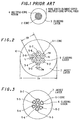
- the inventor's formerly proposed rare earth element-doped multiple-core optical fiber 1 comprises a multiple-core region 4 composed of a plurality of rare earth element-doped cores 2, and a cladding layer 3, wherein a refractive index of the rare earth element-doped cores 2 is higher than that of the cladding layer 3.
- the optical fiber comprises a plurality of cores 5-1, 5-2, - - - - 5-7 each composed of SiO 2 doped with GeO 2 , Al 2 O 3 and Er ions and covered with a cladding layer 6, and a jacket layer 7 for covering the cladding layer-covered cores 5-1, 5-2, - - - - 5-7.
- an outer diameter D 0 of the jacket layer 7 is 125 ⁇ m
- elementary optical fibers each comprising the core 5-1, 5-2, - - - - or 5-7 and the cladding layer 6 are inserted into a quartz glass tube to be drawn under vacuum state therein at a predetermined temperature, and outer surfaces of the cladding layers 6, and the outer surfaces thereof and an inner layer of the quartz glass tube are thermally adhered to each other, so that a rare earth element-doped multiple-core optical fiber having an outer diameter D 0 of 125 ⁇ m is fabricated.
- the cross-sectional configuration of the rare earth element-doped multiple-core optical fiber is shown in Fig. 3, although an ideal configuration is shown in Fig. 2.
- a length thereof providing the maximum gain is approximately 72m, when a signal light having a wavelength of 1.55 ⁇ m and an exci tation light having a wavelength of 1.48 ⁇ m are used.
- the gain is approximately 25dB and a noise index is 5dB, when a power of the signal light is 27dBm, and that of the excitation light is 40mW.
- a gain and a noise index are obtained relative to a power of an output signal light amplified therein as shown in Fig. 4. Further, a gain and a noise index are obtained relative to a wavelength of a signal light as shown in Fig. 5.
- a gain fluctuation is suppressed to be less than 3dB at a wavelength band of 1530 nm to 1560 nm, when a power of the output signal light is -27dBm, and to be less than 1 dB at the same wavelength bane, when the power of the output signal light is -17dBm.
- a noise index is not changed significantly at this wavelength band.
- a rare earth element-doped multiple-core optical fiber in a second preferred embodiment according to the invention will be explained in Fig. 2.
- an outer diameter Dg of the multiple-core is 6.5 ⁇ m
- an outer diameter Dw of each core 5-1, 5-2, - - - - -5-7 is 1.81 ⁇ m, while the other structural parameters remain unchanged from those used in the first preferred embodiment.
- D 0 /Dg is calculated to be approximately 19.2
- 1+2t/Dw is calculated to be approximately 1.36.
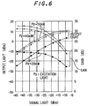
- the rare earth element-doped multiple-core optical fiber is supplied with a signal light having a wavelength of 1.55 ⁇ m and an excitation light having a wavelength of 1.48 ⁇ m, wherein a gain is maximum, when a length thereof is 25m.
- the gain is obtained to be approximately 32dB which is higher than that in the first preferred embodiment, when a power of the signal light is -27dBm, and a power of the excitation light is 40mW. This is because " 1+2t/Dw " is increased from 1.20 to 1.36 as compared to that in the first preferred embodiment.
- Fig. 6 shows an output signal light obtained by amplifying an input signal light and a gain relative to the input signal light in the rare earth element-doped multiple-core optical fiber in the second preferred embodiment which is used for an optical amplifier.
- an outer diameter Dg of the multiple-core is 9.72 ⁇ m
- an outer diameter Dw of each core 5-1, 5-2, - - - -5-7 is 1.95 ⁇ m, while the other structural parameters remain unchanged from those used in the first preferred embodiment.
- D 0 /Dg is calculated to be approximately 12.9
- 1+2t/Dw is calculated to be approximately 2.29.
- the rare earth element-doped multiple-core optical fiber is supplied with an excitation light having a wavelength of 0.98 ⁇ m, wherein a gain is maximum, when a length thereof is 32m.
- the gain is obtained to be approximetory 37dB which is higher than that in the first preferred embodiment, when a power of the signal light is -37dBm, and a power of the excitation light is 120mw.
- Fig. 7 shows a high gain and wide wavelength band characteristics obtained in the third preferred embodiment, wherein gains are flat to be approximately 22dB and 31 dB at wavelengths of 1.53 ⁇ m to 1.56 ⁇ m, when signal powers are -7 dBm and -17 dBm, and the fluctuation of gains is suppressed to be less than 3dB at the same wavelength band, when a signal power is -27 dBm.
- a high gain and wide wavelength band characteristics are obtained by making a value " 1+2t/Dw " large. This is because of the assumption that a signal light and an excitation light are divided equally to be distributed to a plurality of cores 5-1, 5-2, - - - - 5-7. As a result, gains of the divided signal lights in the cores 5-1, 5-2, - - - - 5-7 are not high to provide the wide wavelength band characteristics, so that a gain is obtained to be high at an output end of the rare earth element-doped multiple-core optical fiber in accordance with the summation of amplified powers in the cores 5-1, 5-2, - - - - 5-7, while the wide wavelength band characteristics are maintained.
- a rare earth element-doped multiple-core optical fiber in a fourth preferred embodiment according to the invention will be explained in Fig. 2.
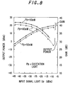
- a doping amount of aluminum in the cores 5-1, 5-2, - - - - 5-7 is increased to be 4,000 weight ppm, and that of Er is increased to be 400 weight ppm, while the other structural parameters are the same as those in the second preferred embodiment.
- Fig. 8 shows relations between an input signal light and a gain, and the input signal light and an output signal light in the fourth preferred embodiment, wherein excitation lights having powers of 40 mw and 50 mw at a wavelength of 1.48 ⁇ m are used, and the maximum gain is 42dB.
- Fig. 9 shows a gain relative to a wavelength of an input signal light in the fourth preferred embodiment, wherein wide wavelength band characteristics of 30 nm are obtained with the maximum gain of 42dB and a gain-fluctuation of 3dB, and gain-fluctuations are suppressed to be less than ⁇ 0.6 dB at a wavelength band of 1.53 ⁇ m to 1.56 ⁇ m for gains of 31dB and 36dB.
- Yb which is a rare earth element is doped into the cores 5-1, 5-2,- - - - 5-7 together with Er, and an excitation light having a wavelength of 1.053 ⁇ m is used.
- Pr is used to amplify a signal light having a wavelength band of 1.3 ⁇ m
- Nd is for a signal light having a wavelength band of 1.3 ⁇ m or 1.06 ⁇ m.
- a rare earth element-doped multiple-core optical fiber in a fifth preferred embodiment according to the invention will be explained in Fig. 2.
- a refractive index nw of the cores 5-1, 5-2, - - - - 5-7 is 1.479, and specific refractive index differences ⁇ n1 and ⁇ n2 are 1.42%, while the other structural parameters are the same as those in the second preferred embodiment.
- a gain is slightly lowered as compared to that in the second preferred embodiment by 0.4 dB.
- a modification is made such that a refractive index of the cores 5-1, 5-2, - - - - 5-7 is 1.485, and specific refractive index differences ⁇ n1 and ⁇ n2 are 1.8%, while the other structural parameters are the same as those in the second preferred embodiment. As a result, a gain is increased by approximately 1.5 dB.
- the number of the cores 5-1, 5-2, - - - - 5-7 may be at least three. Practically, however, it is preferable to be 7, 10, 14, and 19.
- Fig. 10 shows an optical amplifier in a first preferred embodiment according to the invention which comprises optical isolators 10-1 and 10-2, an optical multiplexer 11-1, a rare earth element-doped multiple core optical fiber 8, an optical demultiplexer 11-2, an optical isolator 10-2, an excitation light source 13, and an optical fiber for providing mode field matching regions 14-1 and 14-2.
- a signal light 9-1 is supplied via the optical isolator 10-1 to the mode field-matching region 14-1, while an excitation light 12-1 is emitted from the excitation light source 13 to be supplied via the optical multiplexer 11-1 to the mode field-matching region 14-1, so that the signal light 9-1 and the excitation light 12-1 are supplied to the rare earth element-doped multiple-core optical fiber 8, in which the signal light 9-1 is amplified by absorbing the excitation light 12-1.
- An amplified signal light 9-2 is obtained via the mode field-matching field 14-2 from the optical isolator 10-2, while a remaining portion 12-2 of the excitation light 12-1 which has not contributed to the amplification of the signal light 9-1 is removed from the optical demultiplexer 11-2.
- the optical isolators 10-1 and 10-2 suppress the supply of reflection lights of the amplified signal light 9-2 in the opposite propagation direction.
- the mode field-matching regions 14-1 and 14-2 suppress the reflection lights to lower losses caused by the reflection lights, wherein the signal lights 9-1 and 9-2 are reflected due to mode mis-matching resulted from the difference of specific refractive index differences, ferences, for which specific refractive index ⁇ n1 and ⁇ n2 of the rare earth element-doped multiple-core optical fiber 8 are in a range of 1 to 3%, while those of optical fibers on the side of the optical multiplexer 11-1 and the optical demultiplexer 11-2 are in a range of approximately 0.3%.
- the excitation light 12-1 is supplied to the front stage of the rare earth element-doped multiple-core optical fiber 8, and Er, or Er and Yb are doped into the cores 5-1, 5-2, - - - - 5-7 of the optical fiber 8, when wavelengths of the excitation light 12-1 are 0.9 ⁇ m, 1.05 ⁇ m and 1.48 ⁇ m.
- Fig. 11 shows an optical amplifier in a second preferred embodiment according to the invention, wherein like parts are indicated by like reference numerals as used in Fig. 10, provided that the excitation light 12-1 is supplied at the rear stage of the rare earth element-doped multiple-core optical fiber 8 thereto by the optical multiplexer 11-2, while the remaining portion 12-2 of the excitation light 12-1 which has not contributed to the amplification of the signal light 9-1 is removed from the optical demultiplexer 11-1.
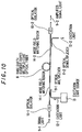
- Fig. 12 shows an optical amplifier in a third preferred embodiment according to the invention, wherein like parts are indicated by like reference numerals as used in Figs. 10 and 11, provided that first and second excitation light sources 13-1 and 13-2 are provided to supply excitation lights 12-1a and 12-1b at the front and rear stages of the rare earth element-doped multiple-core optical fiber 8 thereto by the optical multiplexers 11-1 and 11-2.
- the excitation lights 12-1a and 12-1b may have the same wavelength selected from 0.98 ⁇ m, 1.05 ⁇ m, and 1.48 ⁇ m, or different wavelengths selected therefrom.
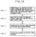
- cores of a high refractive index doped with a rare earth element and aluminum are fabricated, and the cores are coated with cladding layers of a low refractive index to provide elementary optical fibers by an ordinary fabrication process such as flame deposition, outer CVD, etc.
- a predetermined number of the elementary optical fibers are placed in a jacket tube of a low refractive index such as a quartz tube, a quartz tube coated at an inner surface with a film of a low refractive index, a vycor glass tube (Corning Glass Works).
- a low refractive index such as a quartz tube, a quartz tube coated at an inner surface with a film of a low refractive index, a vycor glass tube (Corning Glass Works).
- the jacket tube with the elementary optical fibers is heated from the outer surface thereof, while one end of the jacket tube is sealed to carry out the vacuum drawing at the other end thereof, so that outer surfaces of the elementary optical fibers, and those and the inner surface of the jacket tube are welded to each other to provide an optical fiber preform having no bubble.
- the optical fiber preform is drawn at a heating temperature to provide a rare earth element-doped multiple-core optical fiber.
- members of a low refractive index such as SiO 2 rods, SiO 2 fine particles, SiO 2 rods or particles doped with B 2 O 3 and /or F may be inserted into interstices among the elementary optical fibers and the jacket tube.
- cores of a high refractive index doped with the maximum doping amounts of a rare earth element and aluminum which are equal to values obtained in a conventional single-core optical fiber are prepared for an optical fiber preform. Consequently, a content of the rare earth element is increased as three times in a rare earth element-doped multiple-core optical fiber in the invention as that in the conventional single-core optical fiber to provide a high gain, and a content of aluminum is increased as three times therein as the conventional single-core optical fiber to provide wide wavelength band characteristics.
- the value " 1+2t/Dw " is ranged to be 1.1 to 2.5, where t is a thickness of a cladding layer of an elementary optical fiber, and Dw is an outer diameter of a core for the elementary optical fiber.
- LP 01 modes of excitation lights and signal lights supplied to rare earth element-doped multiple-cores are propagated through the multiple-cores with the approximately same coupling efficiency equal to or more than 80%. In other words, a supplied excitation light and a supplied signal light are equally distributed to each core.
- n is the number of the multiple-cores
- a power of each divided excitation light becomes 1/n as compared to a power of an excitation light supplied to a single-core optical fiber, where an output power of an excitation light source is controlled to be constant.
- a gain is lowered per one core in the invention, while the gain is uniform at a wide wavelength band in the invention.
- the multiple-cores are proximate to be a single core to make it difficult that a wavelength band becomes wide, and, when the above described value is more than 2.5, the excitation and signal lights are partially propagated through cladding layers and a jacket layer to lower a gain.
- Er, Yb, Pr, Nd, Ce, Sm, and Ho may be used for a rare earth element to be doped into multiple-cores, among which Er, or the combination of Er and Yb is preferable to be used at a wavelength band of 1.53 to 1.57 ⁇ m, and Pr or Nd is preferable to be used at a wavelength band of 1.3 ⁇ m.
- specific, refractive index differences ⁇ n1 and ⁇ n2 are preferable to be set more than 1% to increase confining factors of excitation and signal lights into multiple-cores, thereby providing a high gain and wide wavelength band characteristics.
- the specific refractive index differences ⁇ n1 and ⁇ n2 are difficult to be more than 3% due to the fabrication process.
- a ratio D 0 /Dg is ranged to be 12.5 to 30 to provide low loss mode field-matching connection relative to a single mode optical fiber having ordinary low specific refractive index differences ⁇ n1 and ⁇ n2.
- the ratio D 0 /Dg is out of the range of 12.5 to 30, the low loss mode field-matching connection is not obtained to lower a gain.
- SiO 2 -GeO 2 -Al 2 O 3 glass doped with Er and Yb is preferably used for multiple-cores, wherein the doping amount of Er is at least 200 weight ppm to provide a high gain and wide wavelength band characteristics.
- the cores are of SiO 2 glass doped with Er, Yb and Al, at least one of Ge, P, and B may be added thereto provide specific refractive index differences ⁇ n1 and ⁇ n2 of 1 to 3%.
- a material such as B, F, etc. for lowering a refractive index may be added to cladding layers and a jacket layer of SiO 2 glass to further increases the specific refractive index differences ⁇ n1 and ⁇ n2.
Landscapes
- Physics & Mathematics (AREA)
- Engineering & Computer Science (AREA)
- Electromagnetism (AREA)
- Optics & Photonics (AREA)
- Chemical & Material Sciences (AREA)
- Geochemistry & Mineralogy (AREA)
- General Life Sciences & Earth Sciences (AREA)
- Manufacturing & Machinery (AREA)
- Life Sciences & Earth Sciences (AREA)
- Materials Engineering (AREA)
- Organic Chemistry (AREA)
- General Physics & Mathematics (AREA)
- Plasma & Fusion (AREA)
- Lasers (AREA)
- Optical Fibers, Optical Fiber Cores, And Optical Fiber Bundles (AREA)
Claims (16)
- Optische Mehrkernfaser mit Dotierung aus seltenen Erden, umfassend:zumindest drei optische Elementarfasern, jeweils umfassend einen Kern (5-1, 5-2, 5-3...) mit einem Brechungsindex nw und einem Außendurchmesser Dw, und eine Hüllenlage (6) mit einem Brechungsindex nc, wobei nw > nc, und einer Dicke t zum Umhüllen besagten Kerns; undeine Mantellage (7) mit einem Brechungsindex nj, wobei nw > nj, zum Umhüllen von besagten zumindest drei optischen Elementarfasern;wobei besagter Kern mit zumindest einem Element der seltenen Erden und Al von zumindest 1 Gewichtsprozent dotiert ist; undein Wert von 1+2t/Dw, festgelegt durch besagten Außendurchmesser Dw und besagte Dicke t, in einem Bereich von 1,1 bis 2,5 liegt.
- Optische Faser nach Anspruch 1, wobei:
besagtes Element der seltenen Erden zumindest eines ist, das aus Er, Yb, Nd, Ce, Sm und Ho ausgewählt ist. - Optische Faser nach Anspruch 1, wobei:
eine spezifische Brechungsindexdifferenz Δn1, wobei Δn1=[(nw-nc)/nw] x 100%, zwischen besagtem Kern und besagter Hüllenlage, und eine spezifische Brechungsindexdifferenz Δn2, wobei Δn2=[(nw-nj)/nw] x 100%, zwischen besagtem Kern und besagter Mantellage jeweils in einem Bereich von 1 bis 3 % liegen. - Optische Faser nach Anspruch 1, wobei:
ein Verhältnis Do/Dg in einem Bereich von 12,5 bis 25 liegt, wobei Dg ein Außendurchmesser einer Anordnung aus zumindest drei optischen Elementarfasern ist und Do ein Außendurchmesser besagter Mantellage ist. - Optische Faser nach Anspruch 1, wobei:
besagter Kern mit Er und Yb dotiert ist, wobei die Dotierungsmenge von Er zumindest 200 Gewichtsprozent beträgt. - Optische Faser nach Anspruch 5, wobei:
besagter Kern aus SiO2-Glass, dotiert mit zumindest einem der Brechungsindexsteuermaterialien Ge, P und B, zuzüglich zu Er, Yb und Al, ist. - Verfahren zum Herstellen einer optischen Mehrkernfaser mit Dotierung aus seltenen Erden, umfassend die folgenden Verfahrensschritte:Bereitstellen von zumindest drei optischen Elementarfasern, jeweils umfassend einen Kern (5-1, 5-2, 5-3...) mit einem Brechungsindex nw und einem Außendurchmesser Dw und eine Hüllenlage (6) mit einem Brechungsindex nc, wobei nw > nc, und einer Dicke t zum Umhüllen besagten Kerns, wobei besagter Kern mit zumindest einem Element der seltenen Erden und Al von zumindest 1 Gewichtsprozent dotiert ist, und ein Wert 1+2t/Dw, festgelegt durch besagten Außendurchmesser Dw und besagte Dicke t, in einem Bereich von 1,1 bis 2,5 liegt;Anordnen besagter zumindest drei optischen Elementarfasern in einem Mantelrohr;Bereitstellen eines Verbundglieds durch Kollabieren von Zwischenräumen zwischen besagten zumindest drei optischen Elementarfasern und besagtem Mantelrohr, anzuschweißen an Kontaktflächen davon bei einer vorherbestimmten Heiztemperatur; undAufheizen und Ziehen besagten Verbundglieds bei einer vorherbestimmten Temperatur.
- Verfahren nach Anspruch 7, wobei:
der Schritt des Ziehens besagten Verbundglieds bei besagter vorherbestimmten Heiztemperatur nach dem Schritt des Bereitstellens besagten Verbundglieds durchgeführt wird. - Verfahren nach Anspruch 7, wobei:
der Schritt des Bereitstellens besagten Verbundglieds den Schritt des Füllens eines Materials mit einem niedrigeren Brechungsindex als besagter Brechungsindex nw in besagte Zwischenräume zwischen besagte zumindest drei optischen Elementarfasern und besagtes Mantelrohr umfaßt. - Optischer Verstärker, umfassend:eine optische Mehrkernfaser (8) mit Dotierung aus seltenen Erden und einer vorherbestimmten Länge, wobei besagte optische Mehrkernfaser mit Dotierung aus seltenen Erden zumindest drei optische Elementarfasern umfaßt, die jeweils einen Kern (5-1, 5-2, 5-3...) mit einem Brechungsindex nw und einem Außendurchmesser Dw und eine Hüllenlage (6) mit einem Brechungsindex nc, wobei nw > nc, und einer Dicke t zum Umhüllen besagten Kerns und eine Mantellage (7) mit einem Brechungsindex nj, wobei nw > nj, zum Umhüllen besagter zumindest drei optischen Elementarfasern umfaßt, wobei besagter Kern mit zumindest einem Element der seltenen Erden und Al von zumindest 1 Gewichtsprozent dotiert ist und ein Wert 1+2t/Dw, festgelegt durch besagten Außendurchmesser Dw und besagte Dicke t, in einem Bereich von 1,1 bis 2,5 liegt;ein Mittel zum Einführen eines Signallichts (9-1) zum Eingangsende besagter optischen Mehrkernfaser mit Dotierung aus seltenen Erden;ein Mittel zum Fortschreiten eines Anregungslichts (12-1) durch besagte optische Mehrkernfaser mit Dotierung aus seltenen Erden zum Verstärken besagten Signallichts darinnen; undein Mittel zum Ausgeben besagten, so verstärkten Signallichts (9-2) aus einem Ausgangsende besagter optischen Mehrkernfaser mit Dotierung aus seltenen Erden.
- Optischer Verstärker nach Anspruch 10, wobei:
besagtes Anregungslichtfortschreitungsmittel folgendes umfaßt:eine Lichtquelle (13) zum Emittieren besagten Anregungslichts;einen optischen Multiplexer (11-1) zum Einkoppeln besagten Anregungslichts in besagtes Eingangsende besagter optischen Mehrkernfaser mit Dotierung aus seltenen Erden; undeinen optischen Demultiplexer (11-2) zum Entfernen eines verbleibenden Bereichs besagten Anregungslichts an besagtem Ausgangsende besagter optischen Mehrkernfaser mit Dotierung aus seltenen Erden;besagtes Einführmittel folgendes umfaßt:
einen ersten optischen Isolator (10-1), angeordnet zwischen einem Signallichteingangsanschluß besagten optischen Verstärkers und besagtem Eingangsende besagter optischen Mehrkernfaser mit Dotierung aus seltenen Erden zum Fortschreiten besagten Signallichts nur in einer Richtung von besagtem Signallichteingangsanschluß zu besagtem Eingangsende davon;
besagtes Ausgabemittel folgendes umfaßt:
einen zweiten optischen Isolator (10-2), angeordnet zwischen einem Signallichtausgabeanschluß besagten optischen Verstärkers und besagtem Ausgabeende besagter optischen Mehrkernfaser mit Dotierung aus seltenen Erden zum Fortschreiten besagten Signallichts nur in einer Richtung von besagtem Ausgabeende davon zu besagtem Eingangsanschluß. - Optischer Verstärker nach Anspruch 11, ferner umfassend;
erste und zweite Mode-Feldanpassungsbereiche (14-1 bzw. 14-2), bereitgestellt zwischen besagtem ersten optischen Isolator und besagtem Eingangsende besagter optischen Mehrkernfaser mit Dotierung aus seltenen Erden und zwischen besagtem Ausgabeende besagter optischen Mehrkernfaser mit Dotierung aus seltenen Erden und besagtem zweiten Isolator. - Optischer Verstärker nach Anspruch 10, wobei:besagtes Anregungslichtfortschreitungsmittel folgendes umfaßt:eine Lichtquelle (13) zum Emittieren besagten Anregungslichts;einen optischen Multiplexer (11-2) zum Einkoppeln besagten Anregungslichts in besagtes Ausgangsende besagter optischen Mehrkernfaser mit Dotierung aus seltenen Erden; undeinen optischen Demultiplexer (11-1) zum Entfernen eines verbleibenden Bereichs besagten Anregungslichts an besagtem Eingangsende besagter optischen Mehrkernfaser mit Dotierung aus seltenen Erden;besagtes Einführmittel folgendes umfaßt:
einen ersten optischen Isolator (10-1), angeordnet zwischen einem Signallichteingangsanschluß besagten optischen Verstärkers und besagtem Eingangsende besagter optischen Mehrkernfaser mit Dotierung aus seltenen Erden zum Fortschreiten besagten Signallichts nur in einer Richtung von besagtem Signallichtanscfiluß zu besagtem Eingangsende davon;
besagtes Ausgabemittel folgendes umfaßt:
einen zweiten optischen Isolator (10-2), angeordnet zwischen einem Signalausgangsanschluß besagten optischen Verstärkers und besagtem Ausgangsende besagter optischen Mehrkernfaser mit Dotierung aus seltenen Erden zum Fortschreiten besagten Signallichts nur in einer Richtung von besagtem Ausgangsende davon zu besagtem Ausgangsanschluß. - Optischer Verstärker nach Anspruch 13, ferner umfassend:
erste und zweite Mode-Feldanpassungsbereiche (14-1 bzw. 14-2), bereitgestellt zwischen besagtem ersten optischen Isolator und besagtem Eingangsende besagter optischen Mehrkernfaser mit Dotierung aus seltenen Erden und zwischen besagtem Ausgangsende besagter optischen Mehrkernfaser mit Dotierung aus seltenen Erden und besagtem zweiten optischen Isolator. - Optischer Verstärker nach Anspruch 10, wobei:
besagtes Anregungslichtfortschreitungsmittel folgendes umfaßt:erste und zweite Lichtquellen (13-1 bzw. 13-2) zum Emittieren besagter Anregungslichter;optische Multiplexer (11-1, 11-2) zum Einkoppeln besagter Anregungslichter in besagtes Eingangs- und Ausgangsende besagter optischen Mehrkernfaser mit Dotierung aus seltenen Erden; undbesagtes Einführmittel folgendes umfaßt:
einen ersten optischen Isolator (10-1), angeordnet zwischen einem Signallichteingangsanschluß besagten optischen Verstärkers und besagtem Eingangsende besagter optischen Mehrkernfaser mit Dotierung aus seltenen Erden zum Fortschreiten besagten Signallichts nur in einer Richtung von besagtem Signallichteingangsanschluß zu besagtem Eingangsende davon;
besagtes Ausgabemittel folgendes umfaßt:
einen zweiten optischen Isolator (10-2), angeordnet zwischen einem Signallichtausgangsanschluß besagten optischen Verstärkers und besagtem Ausgangsende besagter optischen Mehrkernfaser mit Dotierung aus seltenen Erden zum Fortschreiten besagten Signallichts nur in einer Richtung von besagtem Ausgangsende davon zu besagtem Ausgangsanschluß. - Optischer Verstärker nach Anspruch 15, ferner umfassend:
erste und zweite Mode-Feldanpassungsbereiche (14-1 bzw. 14-2), bereitgestellt zwischen besagtem ersten optischen Isolator und besagtem Eingangsende besagter optischen Mehrkernfaser mit Dotierung aus seltenen Erden beziehungsweise zwischen besagtem Ausgangsende besagter optischen Mehrkernfaser mit Dotierung aus seltenen Erden und besagtem zweiten optischen Isolator.
Applications Claiming Priority (2)
| Application Number | Priority Date | Filing Date | Title |
|---|---|---|---|
| JP175366/94 | 1994-07-27 | ||
| JP6175366A JP2816097B2 (ja) | 1994-07-27 | 1994-07-27 | 希土類元素添加マルチコア光ファイバ、その製造方法、およびその光ファイバを利用した光増幅器 |
Publications (2)
| Publication Number | Publication Date |
|---|---|
| EP0695003A1 EP0695003A1 (de) | 1996-01-31 |
| EP0695003B1 true EP0695003B1 (de) | 1997-09-10 |
Family
ID=15994837
Family Applications (1)
| Application Number | Title | Priority Date | Filing Date |
|---|---|---|---|
| EP95303954A Expired - Lifetime EP0695003B1 (de) | 1994-07-27 | 1995-06-08 | Optische Mehrkernfaser mit Dotierung aus seltenen Erden, Herstellungsmethode dafür und optischer Verstärker mit dieser Faser |
Country Status (4)
| Country | Link |
|---|---|
| US (1) | US5570448A (de) |
| EP (1) | EP0695003B1 (de) |
| JP (1) | JP2816097B2 (de) |
| DE (1) | DE69500687T2 (de) |
Families Citing this family (27)
| Publication number | Priority date | Publication date | Assignee | Title |
|---|---|---|---|---|
| JP3439892B2 (ja) * | 1995-12-11 | 2003-08-25 | 日立電線株式会社 | 希土類元素添加マルチコアファイバ及びその製造方法 |
| JP3773575B2 (ja) * | 1996-01-12 | 2006-05-10 | 富士通株式会社 | ドープファイバ、そのスプライシング方法及び光増幅器 |
| JP3006474B2 (ja) | 1996-02-22 | 2000-02-07 | 日立電線株式会社 | マルチコアファイバ及びこれを用いた光増幅器ならびにこの増幅器を用いた装置 |
| JP3006476B2 (ja) | 1996-03-28 | 2000-02-07 | 日立電線株式会社 | マルチコアファイバ、これを用いた光増幅器、この光増幅器を用いた光増幅中継装置及び光増幅分配装置 |
| GB2310506B (en) * | 1996-02-22 | 2000-10-25 | Hitachi Cable | Rare earth element-doped multiple-core optical fiber and optical systems using them |
| US5802236A (en) * | 1997-02-14 | 1998-09-01 | Lucent Technologies Inc. | Article comprising a micro-structured optical fiber, and method of making such fiber |
| US5847865A (en) * | 1997-02-18 | 1998-12-08 | Regents Of The University Of Minnesota | Waveguide optical amplifier |
| EP0889335B1 (de) * | 1997-06-30 | 2009-06-03 | Hamamatsu Photonics K. K. | Faserbündel und Faserlasergerät unter Verwendung des Faserbündels |
| FR2766583B1 (fr) * | 1997-07-24 | 1999-09-24 | Alsthom Cge Alcatel | Fibre optique multicoeurs |
| KR20010022219A (ko) * | 1997-07-25 | 2001-03-15 | 알프레드 엘. 미첼슨 | 멀티코아 유리 광섬유 및 이의 제조방법 |
| DE19736155C2 (de) * | 1997-08-14 | 2001-12-13 | Forschungsverbund Berlin Ev | Anordnung für einen kompakten Faserlaser zur Erzeugung von Laserstrahlung |
| EP1061385B1 (de) * | 1998-02-05 | 2005-04-13 | Hamamatsu Photonics K.K. | Faseroptische Komponente zur Bildübertragung |
| US6154594A (en) * | 1998-07-15 | 2000-11-28 | Corning Incorporated | Multicore glass optical fiber and methods of manufacturing such fibers |
| US6778747B1 (en) | 1998-09-09 | 2004-08-17 | Corning Incorporated | Radially varying and azimuthally asymmetric optical waveguide fiber |
| KR20010101087A (ko) * | 1999-10-22 | 2001-11-14 | 야마모토 토요미쯔 | 광학 감쇠기 |
| FR2811437A1 (fr) * | 2000-07-06 | 2002-01-11 | Cit Alcatel | Fibre optique a pompage par la gaine et procede de fabrication d'une telle fibre |
| US6711918B1 (en) | 2001-02-06 | 2004-03-30 | Sandia National Laboratories | Method of bundling rods so as to form an optical fiber preform |
| FR2822243B1 (fr) * | 2001-03-16 | 2003-06-20 | Cit Alcatel | Fibre optique photonique a double gaine |
| FR2822242B1 (fr) * | 2001-03-16 | 2003-08-15 | Cit Alcatel | Fibre optique photonique a forte surface effective |
| US8132429B2 (en) * | 2004-04-27 | 2012-03-13 | Silitec Fibers Sa | Method for fabricating an optical fiber, preform for fabricating an optical fiber, optical fiber and apparatus |
| US8033142B2 (en) | 2004-04-27 | 2011-10-11 | Silitec Sa | Method for fabricating an optical fiber, preform for fabricating an optical fiber, optical fiber and apparatus |
| FI125571B (en) * | 2005-02-23 | 2015-11-30 | Liekki Oy | A bundle of optical fibers and a process for making it |
| JP4792464B2 (ja) * | 2005-03-30 | 2011-10-12 | 富士通株式会社 | 光ファイバ及び光増幅器 |
| JP5631979B2 (ja) * | 2009-04-27 | 2014-11-26 | ピコメトリクス、エルエルシー | ファイバにより光結合されたタイムドメイン・テラヘルツシステム内でファイバの延伸により誘起されるタイミングエラーを低減するシステムと方法 |
| CN101694534B (zh) * | 2009-10-22 | 2011-02-16 | 北京交通大学 | 单芯多掺稀土离子区双包层光纤及其制作方法 |
| CN102096147A (zh) * | 2010-12-31 | 2011-06-15 | 北京交通大学 | 一种可熔接的对称结构多芯光纤及其制作方法 |
| CN102262263B (zh) * | 2011-09-01 | 2012-09-05 | 北京交通大学 | 圆芯多扇形区外围多扇形纤芯光纤及其制作方法 |
Family Cites Families (8)
| Publication number | Priority date | Publication date | Assignee | Title |
|---|---|---|---|---|
| GB9010943D0 (en) * | 1990-05-16 | 1990-07-04 | British Telecomm | Wave-guiding structure with lasing properties |
| US5179603A (en) * | 1991-03-18 | 1993-01-12 | Corning Incorporated | Optical fiber amplifier and coupler |
| EP0733600B1 (de) * | 1991-08-26 | 2000-01-12 | Nippon Telegraph And Telephone Corporation | Optische Faser für optische Verstärker |
| JP3221043B2 (ja) * | 1992-04-16 | 2001-10-22 | 日立電線株式会社 | シングルモード伝送用希土類元素添加マルチコアファイバ及びそれを用いた光ファイバ増幅器 |
| US5373526A (en) * | 1992-05-12 | 1994-12-13 | Hughes Aircraft Company | Apparatus and method for optical energy amplification using two-beam coupling |
| JP2830617B2 (ja) * | 1992-06-17 | 1998-12-02 | 日立電線株式会社 | 希土類元素添加マルチコアファイバ及びその製造方法 |
| JP2713031B2 (ja) * | 1992-07-17 | 1998-02-16 | 日立電線株式会社 | 希土類元素添加マルチコアファイバ及びそれを用いた光増幅器 |
| JPH06216441A (ja) * | 1993-01-20 | 1994-08-05 | Hitachi Cable Ltd | 光増幅器用ファイバ及び増幅器 |
-
1994
- 1994-07-27 JP JP6175366A patent/JP2816097B2/ja not_active Expired - Fee Related
-
1995
- 1995-06-07 US US08/476,445 patent/US5570448A/en not_active Expired - Fee Related
- 1995-06-08 EP EP95303954A patent/EP0695003B1/de not_active Expired - Lifetime
- 1995-06-08 DE DE69500687T patent/DE69500687T2/de not_active Expired - Fee Related
Also Published As
| Publication number | Publication date |
|---|---|
| US5570448A (en) | 1996-10-29 |
| EP0695003A1 (de) | 1996-01-31 |
| DE69500687T2 (de) | 1998-04-09 |
| JP2816097B2 (ja) | 1998-10-27 |
| JPH0843644A (ja) | 1996-02-16 |
| DE69500687D1 (de) | 1997-10-16 |
Similar Documents
| Publication | Publication Date | Title |
|---|---|---|
| EP0695003B1 (de) | Optische Mehrkernfaser mit Dotierung aus seltenen Erden, Herstellungsmethode dafür und optischer Verstärker mit dieser Faser | |
| CA2182830C (en) | Rare earth element-doped multiple-core optical fiber and optical systems using the same | |
| EP0602467B1 (de) | Mit seltenen Erden dotierte faseroptische Verstärker | |
| CA2178287C (en) | Rare earth element-doped multiple-core optical fiber and method for fabricating the same | |
| US5067789A (en) | Fiber optic coupling filter and amplifier | |
| CA2021801C (en) | Double active-fiber optical amplifier having a wide-band signal wavelength | |
| US6628876B1 (en) | Method for making a planar waveguide | |
| KR100323207B1 (ko) | 마하-젠더(Mach-Zehnder)디바이스및이의제조방법 | |
| US20030048524A1 (en) | Side-pumped multi-port optical amplifier and method of manufacture using fiber drawing technologies | |
| JP3203178B2 (ja) | 光導波路、光モジュール及び光システム | |
| US5995691A (en) | Waveguide type grating device | |
| EP0454865B1 (de) | Optischer verstärker | |
| CA2173662C (en) | Rare earth element-doped optical fiber amplifier | |
| EP0826988A2 (de) | Integriert optische Notchfilter | |
| Kato et al. | Packaging of large-scale integrated-optic N* N star couplers | |
| US5805332A (en) | Optical fiber amplifier | |
| JP2884919B2 (ja) | 希土類元素添加マルチコアファイバ型カプラ | |
| JP3137165B2 (ja) | 光導波回路の製造方法 | |
| JPS61107324A (ja) | 光フアイバおよび光増幅方法 | |
| JPH0667042A (ja) | 光導波路および形成方法 | |
| JPH05136486A (ja) | 光増幅用icチツプ | |
| JP2000193836A (ja) | 光導波路、光モジュ―ル及び光システム | |
| JPS62484B2 (de) |
Legal Events
| Date | Code | Title | Description |
|---|---|---|---|
| PUAI | Public reference made under article 153(3) epc to a published international application that has entered the european phase |
Free format text: ORIGINAL CODE: 0009012 |
|
| AK | Designated contracting states |
Kind code of ref document: A1 Designated state(s): DE FR GB |
|
| 17P | Request for examination filed |
Effective date: 19960712 |
|
| GRAG | Despatch of communication of intention to grant |
Free format text: ORIGINAL CODE: EPIDOS AGRA |
|
| GRAH | Despatch of communication of intention to grant a patent |
Free format text: ORIGINAL CODE: EPIDOS IGRA |
|
| 17Q | First examination report despatched |
Effective date: 19970210 |
|
| GRAH | Despatch of communication of intention to grant a patent |
Free format text: ORIGINAL CODE: EPIDOS IGRA |
|
| GRAA | (expected) grant |
Free format text: ORIGINAL CODE: 0009210 |
|
| AK | Designated contracting states |
Kind code of ref document: B1 Designated state(s): DE FR GB |
|
| REF | Corresponds to: |
Ref document number: 69500687 Country of ref document: DE Date of ref document: 19971016 |
|
| ET | Fr: translation filed | ||
| PLBE | No opposition filed within time limit |
Free format text: ORIGINAL CODE: 0009261 |
|
| STAA | Information on the status of an ep patent application or granted ep patent |
Free format text: STATUS: NO OPPOSITION FILED WITHIN TIME LIMIT |
|
| 26N | No opposition filed | ||
| REG | Reference to a national code |
Ref country code: GB Ref legal event code: IF02 |
|
| PGFP | Annual fee paid to national office [announced via postgrant information from national office to epo] |
Ref country code: DE Payment date: 20050602 Year of fee payment: 11 |
|
| PGFP | Annual fee paid to national office [announced via postgrant information from national office to epo] |
Ref country code: GB Payment date: 20050608 Year of fee payment: 11 Ref country code: FR Payment date: 20050608 Year of fee payment: 11 |
|
| PG25 | Lapsed in a contracting state [announced via postgrant information from national office to epo] |
Ref country code: GB Free format text: LAPSE BECAUSE OF NON-PAYMENT OF DUE FEES Effective date: 20060608 |
|
| PG25 | Lapsed in a contracting state [announced via postgrant information from national office to epo] |
Ref country code: DE Free format text: LAPSE BECAUSE OF NON-PAYMENT OF DUE FEES Effective date: 20070103 |
|
| GBPC | Gb: european patent ceased through non-payment of renewal fee |
Effective date: 20060608 |
|
| REG | Reference to a national code |
Ref country code: FR Ref legal event code: ST Effective date: 20070228 |
|
| PG25 | Lapsed in a contracting state [announced via postgrant information from national office to epo] |
Ref country code: FR Free format text: LAPSE BECAUSE OF NON-PAYMENT OF DUE FEES Effective date: 20060630 |