EP0694984A1 - Antennenanordnung mit einer unsymmetrischen Masseverteilung insbesondere für drahtlose Telekommunikationssysteme - Google Patents
Antennenanordnung mit einer unsymmetrischen Masseverteilung insbesondere für drahtlose Telekommunikationssysteme Download PDFInfo
- Publication number
- EP0694984A1 EP0694984A1 EP95110731A EP95110731A EP0694984A1 EP 0694984 A1 EP0694984 A1 EP 0694984A1 EP 95110731 A EP95110731 A EP 95110731A EP 95110731 A EP95110731 A EP 95110731A EP 0694984 A1 EP0694984 A1 EP 0694984A1
- Authority
- EP
- European Patent Office
- Prior art keywords
- antenna
- antenna arrangement
- antennas
- conductive surface
- fkt
- Prior art date
- Legal status (The legal status is an assumption and is not a legal conclusion. Google has not performed a legal analysis and makes no representation as to the accuracy of the status listed.)
- Granted
Links
- 230000005540 biological transmission Effects 0.000 claims abstract description 10
- 230000006978 adaptation Effects 0.000 claims description 5
- RYGMFSIKBFXOCR-UHFFFAOYSA-N Copper Chemical compound [Cu] RYGMFSIKBFXOCR-UHFFFAOYSA-N 0.000 claims description 3
- 229910052802 copper Inorganic materials 0.000 claims description 3
- 239000010949 copper Substances 0.000 claims description 3
- 230000005855 radiation Effects 0.000 description 3
- 238000004891 communication Methods 0.000 description 1
- 238000011161 development Methods 0.000 description 1
- 230000018109 developmental process Effects 0.000 description 1
- 230000005672 electromagnetic field Effects 0.000 description 1
- 239000002184 metal Substances 0.000 description 1
- 229910052751 metal Inorganic materials 0.000 description 1
- 238000010295 mobile communication Methods 0.000 description 1
- 230000035945 sensitivity Effects 0.000 description 1
- 238000001228 spectrum Methods 0.000 description 1
Images

Classifications
-
- H—ELECTRICITY
- H01—ELECTRIC ELEMENTS
- H01Q—ANTENNAS, i.e. RADIO AERIALS
- H01Q1/00—Details of, or arrangements associated with, antennas
- H01Q1/12—Supports; Mounting means
- H01Q1/22—Supports; Mounting means by structural association with other equipment or articles
- H01Q1/24—Supports; Mounting means by structural association with other equipment or articles with receiving set
- H01Q1/241—Supports; Mounting means by structural association with other equipment or articles with receiving set used in mobile communications, e.g. GSM
- H01Q1/242—Supports; Mounting means by structural association with other equipment or articles with receiving set used in mobile communications, e.g. GSM specially adapted for hand-held use
-
- H—ELECTRICITY
- H01—ELECTRIC ELEMENTS
- H01Q—ANTENNAS, i.e. RADIO AERIALS
- H01Q1/00—Details of, or arrangements associated with, antennas
- H01Q1/12—Supports; Mounting means
- H01Q1/22—Supports; Mounting means by structural association with other equipment or articles
- H01Q1/24—Supports; Mounting means by structural association with other equipment or articles with receiving set
- H01Q1/241—Supports; Mounting means by structural association with other equipment or articles with receiving set used in mobile communications, e.g. GSM
- H01Q1/246—Supports; Mounting means by structural association with other equipment or articles with receiving set used in mobile communications, e.g. GSM specially adapted for base stations
-
- H—ELECTRICITY
- H01—ELECTRIC ELEMENTS
- H01Q—ANTENNAS, i.e. RADIO AERIALS
- H01Q21/00—Antenna arrays or systems
- H01Q21/29—Combinations of different interacting antenna units for giving a desired directional characteristic
-
- H—ELECTRICITY
- H04—ELECTRIC COMMUNICATION TECHNIQUE
- H04B—TRANSMISSION
- H04B7/00—Radio transmission systems, i.e. using radiation field
- H04B7/02—Diversity systems; Multi-antenna system, i.e. transmission or reception using multiple antennas
- H04B7/04—Diversity systems; Multi-antenna system, i.e. transmission or reception using multiple antennas using two or more spaced independent antennas
- H04B7/08—Diversity systems; Multi-antenna system, i.e. transmission or reception using multiple antennas using two or more spaced independent antennas at the receiving station
- H04B7/0802—Diversity systems; Multi-antenna system, i.e. transmission or reception using multiple antennas using two or more spaced independent antennas at the receiving station using antenna selection
- H04B7/0831—Compensation of the diversity switching process for non-uniform properties or faulty operations of the switches used in the diversity switching process
Definitions
- the invention relates to an antenna arrangement with an asymmetrical mass distribution, in particular for wireless telecommunication systems according to the preamble of patent claim 1.
- the dimensions of the antenna arrangement essentially depend on which carrier frequency for message transmission and which antenna type in the wireless telecommunication system is used.
- a ⁇ / 4 antenna with a carrier frequency of 800-900 MHz ((CT1 +) or GSM standard) has larger dimensions than the same antenna with a carrier frequency of 1880-1900 MHz (DECT standard).
- the antenna arrangements should have an ideal omnidirectional characteristic so that the transmission power of the radio transceiver in the wireless telecommunication system is emitted uniformly in all directions.
- an antenna arrangement with an omnidirectional characteristic ensures that the corresponding radio transmission / radio reception device can be used universally in any environment and that the same transmission range can be achieved in every direction.
- the transmission range in the wireless telecommunication system essentially depends on the transmission power and the receiver sensitivity.
- antenna diversity radio transmission devices there are antenna diversity radio transmission devices / antenna diversity radio reception devices which have at least two antennas.
- Figure 1 shows the basic structure of a DECT-specific cordless mobile part PT (P ortable ermination T) with a handset specific antenna ANT-M, the PT of the handset is connected to a radio part M-FKT.
- Cordless handsets with such a structure are available under the product name "Gigaset 952" - cf. DE-Z: Funkschau 12/1993, pages 24 and 25; "Digital freedom - Gigaset 952: the first DECT telephone”; Author: G. Weckwert - launched in 1993.
- the structure of the cordless handset is also from DE-Z: Funkschau 10/1993; Pages 74 to 77; Title: “Communicate digitally with DECT - DECT chipset from Philips”; Author: Dr. J. Nieder and WO 94/10812 ( Figure 1 with the associated description) known.
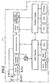
- Figure 2 shows the basic structure of a DECT-specific as antenna diversity radio device / Antenna diversity radio receiving means formed cordless base station FT (F ixed T ermination) with two base station specific diversity antennas B-ANT1, B-ANT2 provided with a radio section B -FKT of the base station FT is connected.
- Cordless base stations with such a structure are available under the product name "Gigaset 952" - cf. DE-Z: Funkschau 12/1993, pages 24 and 25; "Digital freedom - Gigaset 952: the first DECT telephone"; Author: G. Weckwert - launched in 1993.
- the structure of the cordless base station is also from DE-Z: Funkschau 10/1993; Pages 74 to 77; Title: "Communicate digitally with DECT - DECT chipset from Philips”; Author: Dr. J. Nieder and WO 94/10812 ( Figure 1 with the associated description) known.
- an antenna arrangement for radiotelephones in which a main antenna that can be fed with an RF signal is arranged opposite a housing (ground terminal) and in which also an in an opposite area and at an angle between 90 ° and 180 ° to the main antenna, which serves as a counter electrode to this auxiliary antenna is connected to the housing or the ground terminal.
- the current distribution of the entire radiation system can be changed such that a potential minimum occurs in the area of the housing.
- Such an antenna arrangement in particular, the through the neighborhood Influence of the electromagnetic field caused by the human body is reduced and the efficiency of the antenna arrangement is increased.
- Antenna arrangements with an asymmetrical mass distribution are those antenna arrangements in which, for. B. a ⁇ / 4 antenna is arranged on the corner of a metallic body. Antenna arrangements of this type often have an unsatisfactory omnidirectional characteristic.
- the object on which the invention is based is to specify an antenna arrangement with an asymmetrical mass distribution, in particular for wireless telecommunication systems, which has an omnidirectional characteristic, can be used universally and can be produced economically in a simple manner.
- a first antenna and a second antenna are arranged asymmetrically (decentrically) with respect to a conductive surface (asymmetrical mass distribution of the antenna arrangement), the antennas are essentially at right angles to one another on the conductive surface arranged.
- one of the two antennas is arranged essentially in the plane of the conductive surface.
- at least one of the two antennas is optimized in terms of phase and amount with respect to the antenna adaptation.
- FIG. 3 shows an antenna arrangement 1 with two ⁇ / 4 antennas, a first antenna 10a and a second antenna 10b, which are arranged in the corner of a printed circuit board 2. This results in an asymmetrical counterweight for the antennas 10a, 10b (asymmetrical mass distribution of the antenna arrangement).
- the first antenna 10a is arranged perpendicular to a first copper-coated printed circuit board surface 20 (conductive surface) of the printed circuit board 2, which extends through the printed circuit board 2 and has no electrical connection to the printed circuit board surface 20.
- a first strip line 4a is provided on a second circuit board surface 21 opposite the first copper-coated circuit board surface 20, which connects the first antenna 10a to a diode switch 3.
- the diode switch 3 like the strip line 4a, is arranged on the second printed circuit board surface 21.
- On the second circuit board surface 21 are also the handset or base station specific circuit blocks according to Figure 1 or 2, such as. B. the radio part M-FKT or B-FKT, arranged (not shown in Figure 3).
- the second antenna 10b is arranged on the second circuit board surface 21 at right angles to the first antenna 10a, that is to say in the plane of the circuit board 2.
- the base point of the second antenna 10b does not coincide with the base point of the first antenna 10a.
- a second strip line 4b in turn leads to the diode switch 3.
- a third strip line 4c common to the two antennas 10a, 10b leads to the radio part M-FKT, B-FKT according to FIGS. 1 and 2.
- the diode switch 3 has the function that when using the antenna arrangement 1 described above in an antenna diversity radio transmitter / antenna diversity radio receiver, such as. B. the cordless base station FT according to FIG. 2, only one of the two antennas is always activated and at the same time the omnidirectional characteristic described is generated (double use of the antenna arrangement shown).
- the diode switch 3 has a first diode 30 which is connected to the third strip line 4c at the cathode and to the first strip line 4a at the anode and a second diode 31 which is connected to the third strip line 4c and at the cathode the anode is connected to the second strip line 4b. Both diodes 30, 31 are controlled, for example, by the microcontroller according to FIG. 2 with regard to the switching function.
- the antenna arrangement 1 is used in the cordless mobile part PT according to FIG. 1, which is not designed as an antenna diversity radio transmission device / antenna diversity radio reception device, then one of the two antennas 10a, 10b is not fed with an RF signal, that is to say in contrast to the situation with the cordless base station FT used only for the generation of the omnidirectional characteristics.
- the diode switch 3 is not required in this case.
- the two antennas 10a, 10b of the antenna arrangement 1 are further arranged on the printed circuit board 2 in such a way that at least one of the two antennas is optimized in terms of phase and amount with respect to the antenna adaptation.
- the antenna adaptation is carried out via the corresponding strip line 4a, 4b.
Landscapes
- Engineering & Computer Science (AREA)
- Computer Networks & Wireless Communication (AREA)
- Signal Processing (AREA)
- Variable-Direction Aerials And Aerial Arrays (AREA)
- Mobile Radio Communication Systems (AREA)
- Radio Transmission System (AREA)
Abstract
Description
- Die Erfindung betrifft eine Antennenanordnung mit einer unsymmetrischen Masseverteilung, insbesondere für drahtlose Telekommunikationssysteme gemäß dem Oberbegriff des Patentanspruches 1.
- Drahtlose Telekommunikationssysteme mit Funksende-/Funkempfangseinrichtungen, wie beispielsweise Schnurlostelefone nach dem DECT-Standard (Digital European Cordless Telecommunication; vgl. (1) European Telecommunication Standard; prETS 300 175-1...9, 10/1992, Teil 1 bis 9, ETS-Institute 06921 Sofia Antipoles, France; (2) Nachrichtentechnik Elektronik 42 (Jan./Feb. 1992), No.1, Berlin; U. Pilger: "Struktur des DECT-Standards"; Seiten 23 bis 29; (3) Philips Telecommunication Review: "DECT, Universal Cordless Access System"; Vol. 49, Nr. 3, 09/1991, Seiten 68 bis 73) bzw. (CT1+)-Standard, bestehend aus einer Schnurlos-Basisstation und mindestens einem Schnurlos-Mobilteil, oder mobile Handapparate von Mobilfunksystemen nach dem GSM-Standard (Groupe Spéciale Mobile oder Global Systems for Mobile Communication; vgl. Informatik Spektrum, Springer Verlag Berlin, Jg. 14, 1991, No. 3, Seiten 137 bis 152, "Der GSM-Standard - Grundlage für digitale europäische Mobilfunknetze"), verwenden systemspezifische Antennenanordnungen. So unterscheiden sich die Antennenanordnungen z. B. hinsichtlich der
- (1) Abmaße,
- (2) Strahlungscharakteristik und
- (3) Anzahl pro Funksende-/Funkempfangseinrichtung verwendeter Antennen.
- Die Abmaße der Antennenanordnung hängen dabei im wesentlichen davon ab, welche Trägerfrequenz für die Nachrichtenübertragung und welcher Antennentyp in dem drahtlosen Telekommunikationssystem verwendet wird. So hat eine λ/4-Antenne bei einer Trägerfrequenz von 800-900 MHz ((CT1+)- bzw. GSM-Standard) größere Abmaße als die gleiche Antenne bei einer Trägerfrequenz von 1880-1900 MHz (DECT-Standard).
- In bezug auf die Strahlungscharakteristik sollen die Antennenanordnungen eine möglichst ideale Rundstrahlcharakteristik aufweisen, damit die Sendeleistung der Funksende-/Funkempfangseinrichtung in dem drahtlosen Telekommunikationssystem in alle Richtungen gleichmäßig abgestrahlt wird. Darüber hinaus ist bei einer Antennenanordnung mit einer Rundstrahlcharakteristik gewährleistet, daß die entsprechende Funksende-/Funkempfangseinrichtung zum einen universell in jeder Umgebung einsetzbar ist und zum anderen in jeder Richtung die gleiche Übertragungsreichweite erzielt werden kann. Die Übertragungsreichweite in dem drahtlosen Telekommunikationssystem hängt dabei im wesentlichen von der Sendeleistung und der Empfängerempfindlichkeit ab.
- Bezüglich der Anzahl der Antennen gibt es gemäß der WO 94/10764 Antenna Diversity-Funksendeeinrichtungen/Antenna Diversity-Funkempfangseinrichtungen, die mindestens zwei Antennen aufweisen.
- Figur 1 zeigt den prinzipiellen Aufbau eines DECT-spezifischen Schnurlos-Mobilteils PT (Portable Termination) mit einer mobilteilspezifischen Antenne M-ANT, die mit einem Funkteil M-FKT des Mobilteils PT verbunden ist. Schnurlos-Mobilteile mit einem solchen Aufbau sind unter der Produktbezeichnung "Gigaset 952" - vgl. DE-Z: Funkschau 12/1993, Seiten 24 und 25; "Digitale Freiheit - Gigaset 952: Das erste DECT-Telefon"; Autor: G. Weckwert - 1993 auf dem Markt eingeführt worden. Der Aufbau des Schnurlos-Mobilteils ist ferner auch aus der DE-Z: Funkschau 10/1993; Seiten 74 bis 77; Titel: "Digital kommunizieren mit DECT - DECT-Chipsatz von Philips"; Autor: Dr. J. Nieder und der WO 94/10812 (Figur 1 mit der dazugehörigen Beschreibung) bekannt.
- Figur 2 zeigt den prinzipiellen Aufbau einer DECT-spezifischen als Antenna Diversity-Funksendeeinrichtung/Antenna Diversity-Funkempfangseinrichtung ausgebildeten Schnurlos-Basisstation FT (Fixed Termination) mit zwei basisstationsspezifischen Diversity-Antennen B-ANT1, B-ANT2, die mit einem Funkteil B-FKT der Basisstation FT verbunden ist. Schnurlos-Basisstationen mit einem solchen Aufbau sind unter der Produktbezeichnung "Gigaset 952" - vgl. DE-Z: Funkschau 12/1993, Seiten 24 und 25; "Digitale Freiheit - Gigaset 952: Das erste DECT-Telefon"; Autor: G. Weckwert - 1993 auf dem Markt eingeführt worden. Der Aufbau der Schnurlos-Basisstation ist ferner auch aus der DE-Z: Funkschau 10/1993; Seiten 74 bis 77; Titel: "Digital kommunizieren mit DECT - DECT-Chipsatz von Philips"; Autor: Dr. J. Nieder und der WO 94/10812 (Figur 1 mit der dazugehörigen Beschreibung) bekannt.
- Aus der Druckschrift Electronics and Communications in Japan, Part 1, Vol. 76, No. 10, 1993; K.Tsunekawa, K. Kagoshima "Diversity Performance Analysis of Two Parallel Dipole Antennas Mounted on a Small Metal Body", Seiten 80 bis 90 ist eine Antennenkonfiguration bekannt, die als Diversity-Antennenkonfiguration betrieben wird und die aus zwei auf einen metallischen Körper angeordnete λ/2-Dipolantennen besteht.
- Aus der AT- E 52 149 B (Übersetzung der EP- 0 070 150 B1) ist eine Antennenanordnung für Sprechfunkgeräte bekannt, bei der eine mit einem HF-Signal speisbare Hauptantenne gegenüber einem Gehäuse (Masse-Klemme) angeordnet ist und bei der außerdem eine in einem entgegengesetzten Bereich und in einem Winkel zwischen 90° und 180° zur Hauptantenne angeordnete, als Gegenelektrode zu dieser dienende Hilfsantenne mit dem Gehäuse bzw. der Masse-Klemme verbunden ist. Mit dieser Antennenanordnung kann die Stromverteilung des ganzen Abstrahlsystems derart verändert werden, daß im Bereich des Gehäuses ein Potentialminimum auftritt. Durch eine derartig ausgebildete Antennenanordnung werden insbesondere die durch die Nachbarschaft des menschlichen Körpers hervorgerufene Beeinflussung des elektromagnetischen Feldes reduziert und der Wirkungsgrad der Antennenanordnung erhöht.
- Antennenanordnungen mit einer asymmetrischen Masseverteilung, sind solche Antennenanordnungen, bei denen z. B. eine λ/4-Antenne auf der Ecke eines metallischen Körpers angeordnet wird. Derartige Antennenan-ordnungen weisen häufig eine unbefriedigende Rundstrahlcharakteristik auf.
- Die der Erfindung zugrundeliegende Aufgabe besteht darin, eine Antennenanordnung mit einer asymmetrischen Masseverteilung, insbesondere für drahtlose Telekommunikationssysteme anzugeben, die eine Rundstrahlcharakteristik aufweist, universell einsetzbar und auf einfache Weise kostengünstig herstellbar ist.
- Diese Aufgabe wird ausgehend von der in dem Oberbegriff des Patentanspruches 1 definierten Antennenanordnung durch die in dem kennzeichnenden Teil des Patentanspruches 1 angegebenen Merkmale gelöst.
- Um für Antennenanordnungen, bei der zwei unabhängig voneinander speisbare Antennen, eine erste Antenne und eine zweite Antenne gegenüber einer leitenden Fläche asymmetrisch (dezentrisch) angeordnet sind, (asymmetrischen Masseverteilung der Antennenanordnung) eine Rundstrahlcharakteristik zu erzielen, sind die Antennen im wesentlichen rechtwinklig zueinander auf der leitenden Fläche angeordnet. Darüber hinaus ist eine der beiden Antennen im wesentlichen in der Ebene der leitenden Fläche angeordnet. Außerdem ist mindestens eine der beiden Antennen in bezug auf die Antennenanpassung phasen- und betragsmäßig optimiert.
- Vorteilhafte Weiterbildungen der Erfindung sind in den Unteransprüchen angegeben.
- Ein Ausführungsbeispiel der Erfindung wird anhand der Figur 3 erläutert.
- Figur 3 zeigt eine Antennenanordnung 1 mit zwei λ/4-Antennen, einer ersten Antenne 10a und einer zweiten Antenne 10b, die in der Ecke einer Leiterplatte 2 angeordnet sind. Dadurch ergibt sich ein asymmetrisches Gegengewicht für die Antennen 10a, 10b (asymmetrischen Masseverteilung der Antennenanordnung). Senkrecht zu einer ersten kupferbeschichteten Leiterplattenfläche 20 (leitende Fläche) der Leiterplatte 2 ist die erste Antenne 10a angeordnet, die die Leiterplatte 2 durchgreift und dabei keine elektrische Verbindung zu der Leiterplattenfläche 20 aufweist. Am Fußpunkt der Antenne 10a ist auf einer der ersten kupferbeschichteten Leiterplattenfläche 20 gegenüberliegenden zweiten Leiterplattenfläche 21 eine erste Streifenleitung 4a vorgesehen, die die erste Antenne 10a mit einem Diodenschalter 3 verbindet. Der Diodenschalter 3 ist wie die Streifenleitung 4a auf der zweiten Leiterplattenfläche 21 angeordnet. Auf der zweiten Leiterplattenfläche 21 sind außerdem die mobilteil- oder basisstationsspezifischen Schaltungsblöcke nach Figur 1 bzw. 2, wie z. B. das Funkteil M-FKT oder B-FKT, angeordnet (in Figur 3 nicht dargestellt).
- Darüber hinaus ist auf der zweiten Leiterplattenfläche 21 rechtwinklig zu der ersten Antenne 10a, also in der Ebene der Leiterplatte 2, die zweite Antenne 10b angeordnet. Der Fußpunkt der zweiten Antenne 10b fällt dabei nicht mit dem Fußpunkt der ersten Antenne 10a zusammen. Dies ist gleichbedeutend damit, daß die beiden Antennen 10a, 10b unabhängig voneinander mit einem HF-Funksignal, wie es gemäß der Figuren 1 oder 2 in dem Funkteil M-FKT, B-FKT erzeugt wird, gespeist werden können. Vom Fußpunkt der zweiten Antenne 10b führt eine zweite Streifenleitung 4b wiederum zu dem Diodenschalter 3. Von dem Diodenschalter 3 führt eine den beiden Antennen 10a, 10b gemeinsame dritte Streifenleitung 4c zu dem Funkteil M-FKT, B-FKT nach den Figuren 1 und 2.
- Der Diodenschalter 3 hat die Funktion, daß bei der Verwendung der vorstehend beschriebenen Antennenanordnung 1 in einer Antenna Diversity-Funksendeeinrichtung/Antenna Diversity-Funkempfangseinrichtung, wie z. B. die Schnurlos-Basisstation FT nach Figur 2, immer nur eine der beiden Antennen aktiv geschaltet ist und gleichzeitig die beschriebene Rundstrahlcharakteristik erzeugt wird (Doppelausnutzung der dargestellten Antennenanordnung). Für diese Schaltfunktion weist der Diodenschalter 3 eine erste Diode 30, die an der Kathode mit der dritten Streifenleitung 4c und an der Anode mit der ersten Streifenleitung 4a verbunden ist und eine zweite Diode 31 auf, die an der Kathode mit der dritten Streifenleitung 4c und an der Anode mit der zweiten Streifenleitung 4b verbunden ist. Beide Dioden 30, 31 werden beispielsweise von dem Mikrocontroller nach Figur 2 bezüglich der Schaltfunktion gesteuert.
- Wird die Antennenanordnung 1 jedoch in dem Schnurlos-Mobilteil PT nach Figur 1, das nicht als Antenna Diversity-Funksendeeinrichtung/Antenna Diversity-Funkempfangseinrichtung ausgebildet ist, eingesetzt, so wird eine der beiden Antennen 10a, 10b nicht mit einem HF-Signal gespeist, also im Unterschied zu den Verhältnissen bei der Schnurlos-Basisstation FT ausschließlich für die Erzeugung der Rundstrahlcharakteristik genutzt. Der Diodenschalter 3 ist in diesem Fall nicht erforderlich.
- Die beiden Antennen 10a, 10b der Antennenanordnung 1 sind weiterhin derart auf der Leiterplatte 2 angeordnet, daß mindestens eine der beiden Antennen in bezug auf die Antennenanpassung phasen- und betragsmäßig optimiert ist. Die Antennenanpassung wird dabei über die entsprechende Streifenleitung 4a, 4b vorgenommen.
Claims (5)
- Antennenanordnung mit einer unsymmetrischen Masseverteilung, insbesondere für drahtlose Telekommunikationssysteme mit einer ersten Antenne (10a) und einer zweiten Antenne (10b), die gegenüber einer leitenden Fläche (2, 20, 21) einzeln speisbar und asymmetrisch (dezentrisch) auf dieser Fläche (2, 20, 21) angeordnet sind, dadurch gekennzeichnet, daß die Antennen (10a, 10b) im wesentlichen rechtwinklig zueinander auf der leitenden Fläche (2, 20, 21) angeordnet sind, wobei die zweite Antenne (11) im wesentlichen in der Ebene der leitenden Fläche (2, 20, 21) liegt und wobei mindestens eine der beiden Antennen (10a, 10b) in bezug auf die Antennenanpassung phasen- und betragsmäßig optimiert ist.
- Antennenanordnung nach Anspruch 1, dadurch gekennzeichnet, daß ein Leitungsstück (4a, 4b) auf der leitenden Fläche (2, 20, 21) vorgesehen ist, das die Antenne (10a, 10b) in bezug auf die Antennenanpassung phasen- und betragsmäßig optimiert.
- Antennenanordnung nach Anspruch 1 oder 2, dadurch gekennzeichnet, daß die leitende Fläche (2, 20, 21) als kupferbeschichtete Leiterplattenfläche (20) einer mit elektronischen Schaltungen (B-FKT, M-FKT) bestückten Leiterplatte (2) für drahtlose Funksende-/Funkempfangseinrichtungen (FT, PT) ausgebildet ist.
- Verwendung der Antennenanordnung nach Anspruch 1 bis 3 als Diversity-Anordnung.
- Verwendung der Antennenanordnung nach Anspruch 1 bis 4 in einem Schnurlos-Telekommunikationssystem.
Applications Claiming Priority (2)
| Application Number | Priority Date | Filing Date | Title |
|---|---|---|---|
| DE4426252 | 1994-07-25 | ||
| DE4426252A DE4426252C2 (de) | 1994-07-25 | 1994-07-25 | Antennenanordnung, insbesondere für drahtlose Telekommunikationssysteme |
Publications (2)
| Publication Number | Publication Date |
|---|---|
| EP0694984A1 true EP0694984A1 (de) | 1996-01-31 |
| EP0694984B1 EP0694984B1 (de) | 2001-11-14 |
Family
ID=6524052
Family Applications (1)
| Application Number | Title | Priority Date | Filing Date |
|---|---|---|---|
| EP19950110731 Expired - Lifetime EP0694984B1 (de) | 1994-07-25 | 1995-07-10 | Antennenanordnung mit einer unsymmetrischen Masseverteilung insbesondere für drahtlose Telekommunikationssysteme |
Country Status (3)
| Country | Link |
|---|---|
| EP (1) | EP0694984B1 (de) |
| DE (1) | DE4426252C2 (de) |
| ES (1) | ES2168321T3 (de) |
Cited By (1)
| Publication number | Priority date | Publication date | Assignee | Title |
|---|---|---|---|---|
| GB2375893B (en) * | 2000-12-04 | 2005-02-02 | Nec Corp | Wireless communication device with improved antenna structure |
Families Citing this family (1)
| Publication number | Priority date | Publication date | Assignee | Title |
|---|---|---|---|---|
| DE10009883A1 (de) * | 2000-02-24 | 2001-08-30 | Deutsche Telekom Ag | Verfahren und Antennenanordnung zur Verminderung elektromagnetischer Wechselwirkungen eines Funksprechgerätes mit dem menschlichen Gewebe |
Citations (8)
| Publication number | Priority date | Publication date | Assignee | Title |
|---|---|---|---|---|
| AT52149B (de) | 1910-02-26 | 1912-02-10 | George Francois Jaubert | Verfahren zum Betriebe von Verbrenungskraftmaschinen, insbesondere von Dieselmotoren, in Unterseebooten während der Unterwasserfahrt. |
| EP0070150A2 (de) * | 1981-07-10 | 1983-01-19 | BRG Mechatronikai Vállalat | Antennenanordnung für Sprechfunkgeräte |
| JPS6064505A (ja) * | 1983-09-19 | 1985-04-13 | Matsushita Electric Ind Co Ltd | 車載アンテナ装置 |
| US5177493A (en) * | 1990-03-05 | 1993-01-05 | Pioneer Electronic Corporation | Antenna device for movable body |
| WO1994010812A1 (de) | 1992-11-02 | 1994-05-11 | Siemens Aktiengesellschaft | Anordnung zur steuerung einer sende-/empfangseinrichtung, insbesondere von basisstationen und mobilteilen eines schnurlos-telefonsystems |
| FR2699743A1 (fr) * | 1992-12-22 | 1994-06-24 | Motorola Inc | Structure d'antenne en diversité possédant des antennes rapprochées. |
| WO1994029926A1 (de) * | 1993-06-07 | 1994-12-22 | Fuba Hans Kolbe & Co. | Funkantennen-anordnung auf der fensterscheibe eines kraftfahrzeugs |
| DE4339162A1 (de) * | 1993-11-16 | 1995-05-18 | Lindenmeier Heinz | Funkantennenanordnung für den Dezimeterwellenbereich auf einem Kraftfahrzeug |
Family Cites Families (1)
| Publication number | Priority date | Publication date | Assignee | Title |
|---|---|---|---|---|
| FI951956A7 (fi) * | 1992-10-26 | 1995-04-25 | Siemens Ag | Menetelmä ja laite antenninvalinnan ohjaamiseksi radiovastaanottimessa |
-
1994
- 1994-07-25 DE DE4426252A patent/DE4426252C2/de not_active Expired - Lifetime
-
1995
- 1995-07-10 EP EP19950110731 patent/EP0694984B1/de not_active Expired - Lifetime
- 1995-07-10 ES ES95110731T patent/ES2168321T3/es not_active Expired - Lifetime
Patent Citations (9)
| Publication number | Priority date | Publication date | Assignee | Title |
|---|---|---|---|---|
| AT52149B (de) | 1910-02-26 | 1912-02-10 | George Francois Jaubert | Verfahren zum Betriebe von Verbrenungskraftmaschinen, insbesondere von Dieselmotoren, in Unterseebooten während der Unterwasserfahrt. |
| EP0070150A2 (de) * | 1981-07-10 | 1983-01-19 | BRG Mechatronikai Vállalat | Antennenanordnung für Sprechfunkgeräte |
| EP0070150B1 (de) | 1981-07-10 | 1990-04-18 | BRG Mechatronikai Vállalat | Antennenanordnung für Sprechfunkgeräte |
| JPS6064505A (ja) * | 1983-09-19 | 1985-04-13 | Matsushita Electric Ind Co Ltd | 車載アンテナ装置 |
| US5177493A (en) * | 1990-03-05 | 1993-01-05 | Pioneer Electronic Corporation | Antenna device for movable body |
| WO1994010812A1 (de) | 1992-11-02 | 1994-05-11 | Siemens Aktiengesellschaft | Anordnung zur steuerung einer sende-/empfangseinrichtung, insbesondere von basisstationen und mobilteilen eines schnurlos-telefonsystems |
| FR2699743A1 (fr) * | 1992-12-22 | 1994-06-24 | Motorola Inc | Structure d'antenne en diversité possédant des antennes rapprochées. |
| WO1994029926A1 (de) * | 1993-06-07 | 1994-12-22 | Fuba Hans Kolbe & Co. | Funkantennen-anordnung auf der fensterscheibe eines kraftfahrzeugs |
| DE4339162A1 (de) * | 1993-11-16 | 1995-05-18 | Lindenmeier Heinz | Funkantennenanordnung für den Dezimeterwellenbereich auf einem Kraftfahrzeug |
Non-Patent Citations (9)
| Title |
|---|
| "DECT Universal Cordless Access System", vol. 49, no. 3, September 1991 (1991-09-01), pages 68 - 73 |
| "Der GSM-Standard - Grundlage fuer digitale europaeische Mobilfunknetze", INFORMATIK SPEKTRUM, vol. 14, no. 3, 1991, BERLIN, pages 137 - 152 |
| "European Telecommunication Standard", vol. 175, 1992, ETS-INSTITUTE 06921, SOFIA ANTIPOLIS FRANCE, pages: 1 - 9 |
| G. WECKWERT: "Digitale Freiheit - Gigaset 952: Das erste DECT-Telefon", FUNKSCHAU, no. 12, 1993, pages 24 - 25 |
| J. NIEDER: "Digital kommunizieren mit DECT - DECT-Chipsatz von Philips", FUNKSCHAU, no. 10, 1993, pages 74 - 77 |
| K. TSUNEKAWA, K. KAGOSHIMA: "Diversity Performance Analysis of Two Parallel Dipole Antennas Mounted on a Small Metal Body", ELECTRONICS AND COMMUNICATIONS IN JAPAN, vol. 76, no. 10, 1993, pages 80 - 90, XP000438816 |
| PATENT ABSTRACTS OF JAPAN vol. 9, no. 197 (E - 335) 14 August 1985 (1985-08-14) * |
| U. PILGER: "Struktur des DECT-Standards", NACHRICHTENTECHNIK ELEKTRONIK, vol. 42, no. 1, January 1992 (1992-01-01), BERLIN, pages 23 - 29 |
| YAMADA ET AL.: "Diversity Antennas for Base and Mobile Stations in Land Mobile Communication Systems", IEICE TRANSACTIONS, vol. e74, no. 10, TOKYO JP, pages 3202 - 3209, XP000279303 * |
Cited By (2)
| Publication number | Priority date | Publication date | Assignee | Title |
|---|---|---|---|---|
| GB2375893B (en) * | 2000-12-04 | 2005-02-02 | Nec Corp | Wireless communication device with improved antenna structure |
| US6990363B2 (en) | 2000-12-04 | 2006-01-24 | Nec Corporation | Wireless communication device with an improved antenna structure |
Also Published As
| Publication number | Publication date |
|---|---|
| ES2168321T3 (es) | 2002-06-16 |
| DE4426252A1 (de) | 1996-02-08 |
| DE4426252C2 (de) | 1997-10-23 |
| EP0694984B1 (de) | 2001-11-14 |
Similar Documents
| Publication | Publication Date | Title |
|---|---|---|
| DE60318324T2 (de) | Mehrelementantenne mit parasitärem koppler | |
| DE10124142B4 (de) | Planarantenne und damit ausgerüstete Einrichtung für drahtlose Kommunikation | |
| DE69830096T2 (de) | Antennenanordnung für kleines Funkkommunikationsgerät | |
| DE69910561T2 (de) | Mehrfrequenzband-antenna | |
| DE60129475T2 (de) | Eingebaute Antenne für ein mobiles Funkgerät | |
| DE60200738T2 (de) | Antenne für mobiles Telefon | |
| DE3689455T2 (de) | Tragbares Rundfunkgerät. | |
| DE60104851T2 (de) | Konvertierbare schleifen-/invertierte f-antennen und drahtlose kommunikationsgeräte mit derartigen antennen | |
| DE69924104T2 (de) | Asymmetrische Dipolantennenanordnung | |
| DE60205720T2 (de) | Zwischen mehreren Frequenzbändern schaltbare Antenne für tragbare Endgeräte | |
| DE60118827T2 (de) | Antennenverbinder | |
| DE19533247A1 (de) | Antennenstruktur und mit dieser versehene Funk-Kommunikationseinrichtung | |
| DE69831375T2 (de) | Antennenkonnektor für einen tragbaren Funkgerät | |
| EP0508299B1 (de) | Funksprechgerät mit zugehöriger Geräteantenne | |
| DE69826174T2 (de) | Mobiles Funkgerät | |
| DE69936648T2 (de) | Substratantenne mit einem element zur verhinderung von energiekopplung zwischen antenne und leitern | |
| DE60017169T2 (de) | Antennenanordnung mit aktivem element und reflektor | |
| DE10196547B3 (de) | Eingebettete Antenne für ein Mobilendgerät | |
| WO1998009342A1 (en) | Antenna device and method for portable radio equipment | |
| DE60318813T2 (de) | Kompakte Diversity-Antenne | |
| DE60308903T2 (de) | Auf einer oberfläche montierbare klemme zur verwendung für ein mobiles kommunikationsgerät | |
| EP0777939B1 (de) | Antennenschalter für drahtlose antenna diversity-telekommunikationsgeräte mit zwei antennen | |
| DE602005005935T2 (de) | Tragbares Mobilfunkgerät mit integrierter Antenne und Tastatur und dazugehörige Verfahren | |
| DE602005006159T2 (de) | Dvb-h-antennen (digital video broadcast-handheld) für drahtlose endgeräte | |
| DE60208731T2 (de) | Eingebaute Mehrband-Planarantenne mit Inverted-L-Haupt- und Parasitär- Antennenelementen |
Legal Events
| Date | Code | Title | Description |
|---|---|---|---|
| PUAI | Public reference made under article 153(3) epc to a published international application that has entered the european phase |
Free format text: ORIGINAL CODE: 0009012 |
|
| AK | Designated contracting states |
Kind code of ref document: A1 Designated state(s): CH ES FR GB IT LI NL SE |
|
| 17P | Request for examination filed |
Effective date: 19960219 |
|
| 17Q | First examination report despatched |
Effective date: 19981008 |
|
| GRAG | Despatch of communication of intention to grant |
Free format text: ORIGINAL CODE: EPIDOS AGRA |
|
| GRAG | Despatch of communication of intention to grant |
Free format text: ORIGINAL CODE: EPIDOS AGRA |
|
| GRAH | Despatch of communication of intention to grant a patent |
Free format text: ORIGINAL CODE: EPIDOS IGRA |
|
| GRAH | Despatch of communication of intention to grant a patent |
Free format text: ORIGINAL CODE: EPIDOS IGRA |
|
| GRAA | (expected) grant |
Free format text: ORIGINAL CODE: 0009210 |
|
| AK | Designated contracting states |
Kind code of ref document: B1 Designated state(s): CH ES FR GB IT LI NL SE |
|
| REG | Reference to a national code |
Ref country code: CH Ref legal event code: NV Representative=s name: SIEMENS SCHWEIZ AG Ref country code: CH Ref legal event code: EP |
|
| REG | Reference to a national code |
Ref country code: GB Ref legal event code: IF02 |
|
| GBT | Gb: translation of ep patent filed (gb section 77(6)(a)/1977) |
Effective date: 20020122 |
|
| REG | Reference to a national code |
Ref country code: ES Ref legal event code: FG2A Ref document number: 2168321 Country of ref document: ES Kind code of ref document: T3 |
|
| PGFP | Annual fee paid to national office [announced via postgrant information from national office to epo] |
Ref country code: NL Payment date: 20020715 Year of fee payment: 8 |
|
| PGFP | Annual fee paid to national office [announced via postgrant information from national office to epo] |
Ref country code: SE Payment date: 20020724 Year of fee payment: 8 |
|
| PG25 | Lapsed in a contracting state [announced via postgrant information from national office to epo] |
Ref country code: LI Free format text: LAPSE BECAUSE OF NON-PAYMENT OF DUE FEES Effective date: 20020731 Ref country code: CH Free format text: LAPSE BECAUSE OF NON-PAYMENT OF DUE FEES Effective date: 20020731 |
|
| PLBE | No opposition filed within time limit |
Free format text: ORIGINAL CODE: 0009261 |
|
| STAA | Information on the status of an ep patent application or granted ep patent |
Free format text: STATUS: NO OPPOSITION FILED WITHIN TIME LIMIT |
|
| 26N | No opposition filed | ||
| REG | Reference to a national code |
Ref country code: CH Ref legal event code: PL |
|
| PG25 | Lapsed in a contracting state [announced via postgrant information from national office to epo] |
Ref country code: SE Free format text: LAPSE BECAUSE OF NON-PAYMENT OF DUE FEES Effective date: 20030711 |
|
| PG25 | Lapsed in a contracting state [announced via postgrant information from national office to epo] |
Ref country code: NL Free format text: LAPSE BECAUSE OF NON-PAYMENT OF DUE FEES Effective date: 20040201 |
|
| EUG | Se: european patent has lapsed | ||
| NLV4 | Nl: lapsed or anulled due to non-payment of the annual fee |
Effective date: 20040201 |
|
| REG | Reference to a national code |
Ref country code: GB Ref legal event code: 732E Free format text: REGISTERED BETWEEN 20101028 AND 20101103 |
|
| PGFP | Annual fee paid to national office [announced via postgrant information from national office to epo] |
Ref country code: GB Payment date: 20140721 Year of fee payment: 20 Ref country code: FR Payment date: 20140721 Year of fee payment: 20 Ref country code: ES Payment date: 20140728 Year of fee payment: 20 |
|
| PGFP | Annual fee paid to national office [announced via postgrant information from national office to epo] |
Ref country code: IT Payment date: 20140731 Year of fee payment: 20 |
|
| REG | Reference to a national code |
Ref country code: GB Ref legal event code: PE20 Expiry date: 20150709 |
|
| REG | Reference to a national code |
Ref country code: ES Ref legal event code: FD2A Effective date: 20151026 |
|
| PG25 | Lapsed in a contracting state [announced via postgrant information from national office to epo] |
Ref country code: GB Free format text: LAPSE BECAUSE OF EXPIRATION OF PROTECTION Effective date: 20150709 |
|
| PG25 | Lapsed in a contracting state [announced via postgrant information from national office to epo] |
Ref country code: ES Free format text: LAPSE BECAUSE OF EXPIRATION OF PROTECTION Effective date: 20150711 |