EP0694124B1 - Zerstäubungssieb und brennstoffeinspritzventil mit einem zerstäubungssieb - Google Patents
Zerstäubungssieb und brennstoffeinspritzventil mit einem zerstäubungssieb Download PDFInfo
- Publication number
- EP0694124B1 EP0694124B1 EP95903245A EP95903245A EP0694124B1 EP 0694124 B1 EP0694124 B1 EP 0694124B1 EP 95903245 A EP95903245 A EP 95903245A EP 95903245 A EP95903245 A EP 95903245A EP 0694124 B1 EP0694124 B1 EP 0694124B1
- Authority
- EP
- European Patent Office
- Prior art keywords
- injection valve
- fuel injection
- atomizing
- sieve
- fuel
- Prior art date
- Legal status (The legal status is an assumption and is not a legal conclusion. Google has not performed a legal analysis and makes no representation as to the accuracy of the status listed.)
- Expired - Lifetime
Links
- 239000000446 fuel Substances 0.000 title claims description 267
- 238000002347 injection Methods 0.000 title claims description 70
- 239000007924 injection Substances 0.000 title claims description 70
- 239000007921 spray Substances 0.000 claims description 140
- 125000006850 spacer group Chemical group 0.000 claims description 106
- 230000001681 protective effect Effects 0.000 claims description 89
- 238000011144 upstream manufacturing Methods 0.000 claims description 25
- 238000002485 combustion reaction Methods 0.000 claims description 23
- 239000000203 mixture Substances 0.000 claims description 18
- 239000004744 fabric Substances 0.000 claims description 14
- 239000002184 metal Substances 0.000 claims description 14
- 229910052751 metal Inorganic materials 0.000 claims description 14
- 239000000463 material Substances 0.000 claims description 13
- 230000009467 reduction Effects 0.000 claims description 8
- 239000010410 layer Substances 0.000 claims description 7
- 239000004033 plastic Substances 0.000 claims description 7
- 238000000926 separation method Methods 0.000 claims description 6
- 239000004809 Teflon Substances 0.000 claims description 5
- 229920006362 Teflon® Polymers 0.000 claims description 5
- 239000002356 single layer Substances 0.000 claims description 2
- 239000010703 silicon Substances 0.000 claims 1
- 229910052710 silicon Inorganic materials 0.000 claims 1
- 239000007789 gas Substances 0.000 description 198
- 238000000889 atomisation Methods 0.000 description 32
- 230000008901 benefit Effects 0.000 description 19
- 238000002360 preparation method Methods 0.000 description 14
- 230000002093 peripheral effect Effects 0.000 description 12
- 238000009826 distribution Methods 0.000 description 8
- 230000006872 improvement Effects 0.000 description 8
- 238000012545 processing Methods 0.000 description 8
- 238000000034 method Methods 0.000 description 7
- 230000015572 biosynthetic process Effects 0.000 description 6
- 238000010586 diagram Methods 0.000 description 6
- 230000002829 reductive effect Effects 0.000 description 6
- 238000012549 training Methods 0.000 description 6
- 238000009736 wetting Methods 0.000 description 6
- PIJPYDMVFNTHIP-UHFFFAOYSA-L lead sulfate Chemical compound [PbH4+2].[O-]S([O-])(=O)=O PIJPYDMVFNTHIP-UHFFFAOYSA-L 0.000 description 5
- 238000004519 manufacturing process Methods 0.000 description 5
- 238000007789 sealing Methods 0.000 description 5
- 238000003466 welding Methods 0.000 description 5
- 238000001704 evaporation Methods 0.000 description 4
- 230000008020 evaporation Effects 0.000 description 4
- 239000003595 mist Substances 0.000 description 4
- 230000036961 partial effect Effects 0.000 description 4
- 238000005507 spraying Methods 0.000 description 4
- XLYOFNOQVPJJNP-UHFFFAOYSA-N water Substances O XLYOFNOQVPJJNP-UHFFFAOYSA-N 0.000 description 4
- 238000004026 adhesive bonding Methods 0.000 description 3
- 238000005520 cutting process Methods 0.000 description 3
- 230000001419 dependent effect Effects 0.000 description 3
- 238000013461 design Methods 0.000 description 3
- 230000000694 effects Effects 0.000 description 3
- 239000002737 fuel gas Substances 0.000 description 3
- 238000010438 heat treatment Methods 0.000 description 3
- 230000008092 positive effect Effects 0.000 description 3
- 230000008569 process Effects 0.000 description 3
- 230000005855 radiation Effects 0.000 description 3
- 238000007493 shaping process Methods 0.000 description 3
- 238000003856 thermoforming Methods 0.000 description 3
- NINIDFKCEFEMDL-UHFFFAOYSA-N Sulfur Chemical compound [S] NINIDFKCEFEMDL-UHFFFAOYSA-N 0.000 description 2
- 230000004323 axial length Effects 0.000 description 2
- 238000009954 braiding Methods 0.000 description 2
- 230000008859 change Effects 0.000 description 2
- 238000006243 chemical reaction Methods 0.000 description 2
- 238000011161 development Methods 0.000 description 2
- 230000018109 developmental process Effects 0.000 description 2
- 238000005530 etching Methods 0.000 description 2
- 230000002209 hydrophobic effect Effects 0.000 description 2
- 238000001746 injection moulding Methods 0.000 description 2
- 239000007788 liquid Substances 0.000 description 2
- 239000000126 substance Substances 0.000 description 2
- 229910052717 sulfur Inorganic materials 0.000 description 2
- 239000011593 sulfur Substances 0.000 description 2
- 239000002918 waste heat Substances 0.000 description 2
- 240000005611 Agrostis gigantea Species 0.000 description 1
- XUIMIQQOPSSXEZ-UHFFFAOYSA-N Silicon Chemical compound [Si] XUIMIQQOPSSXEZ-UHFFFAOYSA-N 0.000 description 1
- 230000001133 acceleration Effects 0.000 description 1
- 230000009471 action Effects 0.000 description 1
- 230000002411 adverse Effects 0.000 description 1
- 230000000712 assembly Effects 0.000 description 1
- 238000000429 assembly Methods 0.000 description 1
- 238000005422 blasting Methods 0.000 description 1
- 238000007664 blowing Methods 0.000 description 1
- 238000009835 boiling Methods 0.000 description 1
- 230000000052 comparative effect Effects 0.000 description 1
- 238000010276 construction Methods 0.000 description 1
- 238000004049 embossing Methods 0.000 description 1
- 230000003628 erosive effect Effects 0.000 description 1
- 238000005562 fading Methods 0.000 description 1
- 230000002349 favourable effect Effects 0.000 description 1
- 239000012530 fluid Substances 0.000 description 1
- 238000003780 insertion Methods 0.000 description 1
- 230000037431 insertion Effects 0.000 description 1
- 238000009434 installation Methods 0.000 description 1
- 238000005304 joining Methods 0.000 description 1
- 238000002372 labelling Methods 0.000 description 1
- 230000014759 maintenance of location Effects 0.000 description 1
- 150000002739 metals Chemical class 0.000 description 1
- 238000012986 modification Methods 0.000 description 1
- 230000004048 modification Effects 0.000 description 1
- 238000003825 pressing Methods 0.000 description 1
- 230000002265 prevention Effects 0.000 description 1
- 230000000717 retained effect Effects 0.000 description 1
- 239000004065 semiconductor Substances 0.000 description 1
- 238000007873 sieving Methods 0.000 description 1
- 238000005476 soldering Methods 0.000 description 1
- 239000000243 solution Substances 0.000 description 1
- 229910001220 stainless steel Inorganic materials 0.000 description 1
- 239000010935 stainless steel Substances 0.000 description 1
- 239000011273 tar residue Substances 0.000 description 1
- 238000010792 warming Methods 0.000 description 1
Images


Classifications
-
- F—MECHANICAL ENGINEERING; LIGHTING; HEATING; WEAPONS; BLASTING
- F02—COMBUSTION ENGINES; HOT-GAS OR COMBUSTION-PRODUCT ENGINE PLANTS
- F02M—SUPPLYING COMBUSTION ENGINES IN GENERAL WITH COMBUSTIBLE MIXTURES OR CONSTITUENTS THEREOF
- F02M61/00—Fuel-injectors not provided for in groups F02M39/00 - F02M57/00 or F02M67/00
- F02M61/16—Details not provided for in, or of interest apart from, the apparatus of groups F02M61/02 - F02M61/14
- F02M61/18—Injection nozzles, e.g. having valve seats; Details of valve member seated ends, not otherwise provided for
- F02M61/188—Spherical or partly spherical shaped valve member ends
-
- F—MECHANICAL ENGINEERING; LIGHTING; HEATING; WEAPONS; BLASTING
- F02—COMBUSTION ENGINES; HOT-GAS OR COMBUSTION-PRODUCT ENGINE PLANTS
- F02M—SUPPLYING COMBUSTION ENGINES IN GENERAL WITH COMBUSTIBLE MIXTURES OR CONSTITUENTS THEREOF
- F02M53/00—Fuel-injection apparatus characterised by having heating, cooling or thermally-insulating means
- F02M53/04—Injectors with heating, cooling, or thermally-insulating means
- F02M53/06—Injectors with heating, cooling, or thermally-insulating means with fuel-heating means, e.g. for vaporising
-
- F—MECHANICAL ENGINEERING; LIGHTING; HEATING; WEAPONS; BLASTING
- F02—COMBUSTION ENGINES; HOT-GAS OR COMBUSTION-PRODUCT ENGINE PLANTS
- F02M—SUPPLYING COMBUSTION ENGINES IN GENERAL WITH COMBUSTIBLE MIXTURES OR CONSTITUENTS THEREOF
- F02M61/00—Fuel-injectors not provided for in groups F02M39/00 - F02M57/00 or F02M67/00
- F02M61/16—Details not provided for in, or of interest apart from, the apparatus of groups F02M61/02 - F02M61/14
- F02M61/18—Injection nozzles, e.g. having valve seats; Details of valve member seated ends, not otherwise provided for
- F02M61/1806—Injection nozzles, e.g. having valve seats; Details of valve member seated ends, not otherwise provided for characterised by the arrangement of discharge orifices, e.g. orientation or size
-
- F—MECHANICAL ENGINEERING; LIGHTING; HEATING; WEAPONS; BLASTING
- F02—COMBUSTION ENGINES; HOT-GAS OR COMBUSTION-PRODUCT ENGINE PLANTS
- F02M—SUPPLYING COMBUSTION ENGINES IN GENERAL WITH COMBUSTIBLE MIXTURES OR CONSTITUENTS THEREOF
- F02M61/00—Fuel-injectors not provided for in groups F02M39/00 - F02M57/00 or F02M67/00
- F02M61/16—Details not provided for in, or of interest apart from, the apparatus of groups F02M61/02 - F02M61/14
- F02M61/18—Injection nozzles, e.g. having valve seats; Details of valve member seated ends, not otherwise provided for
- F02M61/1853—Orifice plates
-
- F—MECHANICAL ENGINEERING; LIGHTING; HEATING; WEAPONS; BLASTING
- F02—COMBUSTION ENGINES; HOT-GAS OR COMBUSTION-PRODUCT ENGINE PLANTS
- F02M—SUPPLYING COMBUSTION ENGINES IN GENERAL WITH COMBUSTIBLE MIXTURES OR CONSTITUENTS THEREOF
- F02M69/00—Low-pressure fuel-injection apparatus ; Apparatus with both continuous and intermittent injection; Apparatus injecting different types of fuel
- F02M69/04—Injectors peculiar thereto
- F02M69/047—Injectors peculiar thereto injectors with air chambers, e.g. communicating with atmosphere for aerating the nozzles
-
- Y—GENERAL TAGGING OF NEW TECHNOLOGICAL DEVELOPMENTS; GENERAL TAGGING OF CROSS-SECTIONAL TECHNOLOGIES SPANNING OVER SEVERAL SECTIONS OF THE IPC; TECHNICAL SUBJECTS COVERED BY FORMER USPC CROSS-REFERENCE ART COLLECTIONS [XRACs] AND DIGESTS
- Y10—TECHNICAL SUBJECTS COVERED BY FORMER USPC
- Y10S—TECHNICAL SUBJECTS COVERED BY FORMER USPC CROSS-REFERENCE ART COLLECTIONS [XRACs] AND DIGESTS
- Y10S239/00—Fluid sprinkling, spraying, and diffusing
- Y10S239/23—Screens
-
- Y—GENERAL TAGGING OF NEW TECHNOLOGICAL DEVELOPMENTS; GENERAL TAGGING OF CROSS-SECTIONAL TECHNOLOGIES SPANNING OVER SEVERAL SECTIONS OF THE IPC; TECHNICAL SUBJECTS COVERED BY FORMER USPC CROSS-REFERENCE ART COLLECTIONS [XRACs] AND DIGESTS
- Y10—TECHNICAL SUBJECTS COVERED BY FORMER USPC
- Y10S—TECHNICAL SUBJECTS COVERED BY FORMER USPC CROSS-REFERENCE ART COLLECTIONS [XRACs] AND DIGESTS
- Y10S239/00—Fluid sprinkling, spraying, and diffusing
- Y10S239/90—Electromagnetically actuated fuel injector having ball and seat type valve
Definitions
- the invention is based on an atomizing sieve or a fuel injector with an atomizing sieve according to the genus of claim 1 and Claim 10.
- DE-OS 23 06 362 a device for Known fuel processing for an internal combustion engine, with at least one fuel injector is metered, which in turn in the injection valve downstream intake pipe or a branch pipe of the Intake pipe meets a sieve arranged there.
- this device should be used especially during the cold start and warm-up phase of the internal combustion engine a good ignitable fuel-air mixture can be generated without to increase the amount of fuel significantly. Good pre-evaporation of the fuel occurs when the sieve is designed to be electrically heated. The great There is no distance between the sieve and the injection valve precisely targeted jet shapes, rather the Fuel sprayed widely.
- the atomizing sieve according to the invention characteristic features of claim 1 has in contrast the advantage of being very simple and easy Fuel injectors very assemblable component inexpensive and in a variety of Design variants can be produced quickly and safely an excellent atomization of the hosed Guaranteed fuel.
- the atomizing sieve made of a stainless metal, a plastic, Teflon or PTC, i.e. a material with to produce a positive resistance-temperature coefficient.
- Teflon is suitable as a material for the atomizing sieve especially when the atomizing sieve is used should take place under extreme temperature conditions.
- a Atomizing sieve made of Teflon is namely hydrophobic and therefore prevents icing up to temperatures -40 ° C.
- a particularly advantageous embodiment of the Atomizing sieve results when a mesh size of around 0.2 mm of the sieve is provided. It can be an advantage also be for special applications, the mesh of the Atomizing sieve in addition to a single-layer variant two- or to produce multiple layers, the multiple fabric layers are intertwined.
- the mesh density can be in advantageous for the area adjustment of the Atomization quality can be designed variably.
- the fabric of the Atomizing sieve can have a constant mesh size have, but also become denser towards the outer sieve zone or vice versa also towards the center of the atomizing sieve be condensed.
- the atomizing sieve as one Bimetal sieve, consisting of two metals with different coefficients of thermal expansion, form by the mesh openings for example be introduced by means of a laser.
- a bimetal strainer has the advantage that the geometry of the sieve, e.g. B. the shape of the bulge, with different Operating temperature can be changed in the desired manner can shape the atomization quality and the jet Adapt the requirements of the respective operating conditions.
- a heatable atomizing sieve is also advantageous Fuel evaporation. Temperature-dependent screen materials ensure that the resistance is variable. So increases z. B. with positive PTC materials Resistance temperature coefficient of resistance at Warming. As a result, electrical heating, especially when the internal combustion engine is cold started, better evaporation of the fuel can be achieved.
- a circumferential clamping ring is another advantage represents the circumferential direction of the atomizing sieve and in which the sieve sheet is clamped, clamped or is encapsulated. This clamping ring enables a very simple assembly of the atomizing sieve on one Fuel injector in one process step can be done by clamping.
- the fuel injector according to the invention with the characterizing features of claim 10 has the advantage that with a very low cost an atomizing screen very easy to mount on the fuel injector is that to further improve the Atomization quality also contributes without gas containment, since the fuel hitting the atomizing sieve in particular fine on the mesh of the atomizing sieve in the smallest Droplet is atomized, reducing exhaust gas emissions Internal combustion engine further reduced and also one Reduction in fuel consumption is achieved.
- the Fuel is generated by the impact on the atomizing sieve extremely slowed down and diverted into the respective mesh. The collision causes a tear or one Cutting up the fuel. In the area of Atomizing sieve therefore finds an energy conversion of the kinetic energy stored in the fuel instead.
- At least one pulsed fuel jet which e.g. from one nozzle opening or from several spray openings an orifice plate can escape.
- an orifice plate By tearing of fuel on the atomizing screen and passing through of fuel through the fine mesh of the Atomizing sieve is created downstream of the Atomizing sieve a fine droplet mist.
- the Fuel droplets now have a much larger size Surface than the fuel jets before hitting on the atomizing sieve, which in turn is an indication of good Atomization is.
- the characterizing features of claim 10 further Advantages and positive effects.
- the atomizing sieve offers downstream of the nozzle opening or the spray orifice plate increased security against icing inside the fuel injector, especially the orifice plate.
- fuel can still be jetted off much lower temperatures (even at high temperatures) Air humidity) take place than is the case with fuel injectors without the atomizing sieve.
- the Atomizing sieve acts as an "ice trap".
- Bad quality fuel namely has u. a.
- Fuels containing sulfur have the disadvantage that that sulfur when it hits colder components condenses, which results in layers of Deposit lead sulfate on metallic components. Similar to Plugging causes these layers to clog Openings on the fuel injector, for example the Spray openings of the spray orifice plate.
- the atomizing sieve effectively ensures that there are no layers of lead sulfate upstream of the atomizing screen inside of the fuel injector are formed, since there the chemical suction tube atmosphere is not effective.
- Atomizer improver from the fuel injector escaping fuel as well as a protective element against numerous influences of mechanical and chemical nature.
- the concave bulge of the atomizing sieve ensures that part of the deposited fuel in at least one deepest area can converge.
- the collected Fuel represents a comparative for a short time amount of liquid at rest, to which then again new Fuel hits. This configuration contributes to particularly high atomization quality. It can also be so do not collect fuel at the outer edge of the sieve.
- the atomizing sieve with an outer circumferential area in a protective cap is poured.
- the atomizing sieve is with one Retention dimension embedded in the protective cap, d. H. the the downstream cap end of the protective cap limits this Fuel injector downstream during the deepest area of the atomizing sieve further upstream lies and therefore not from the fuel injector protrudes.
- This spatial arrangement offers one adequate protection against mechanical damage.
- the Protective cap is advantageous as one Protective crown trained, which benefits in Dripping behavior of the fuel injector compared result in a protective cap with a circumferential protective ring.
- Atomizing sieve By forming several bulges on Atomizing sieve gives further advantages because for different use cases very specific Beam geometries or beam images can be generated.
- the through the spray hole arrangement or inclination predetermined jet angle of the fuel also remain downstream atomizing sieve advantageously obtained.
- One through the spray openings z. B. predetermined The atomizing sieve does not create double radiation negatively influenced, but can be caused by upstream or Beam splitters arranged downstream of the atomizing sieve be reinforced.
- the gas supply can be arranged so that both upstream and also downstream of the atomizing sieve the gas on the Fuel is directed. Ideally they are Gas supply channels downstream of the atomizing screen in the Protective cap inserted and aligned so that it with their imaginary extensions tangentially Touch the bulge of the atomizing sieve downstream.
- the treatment quality is due to the gas enclosure further increased.
- the atomizing sieve a clear spatial distance from the least a spray opening of the injector downstream to arrange.
- the goal is, with one Atomizer attachment consisting of a spacer and the atomizing sieve when the Injector the point of fuel atomization in the ideal position in the air flow of the intake manifold To lay the internal combustion engine so that the wall film formation of the To reduce or prevent fuel in the intake manifold, resulting in a significant reduction in Exhaust emissions, especially the proportion of HC, is achieved.
- the spacer with the advantageously on his atomizer sieve attached downstream end thus for a spatial separation of metering and Preparation of the fuel.
- the injection valve must a fuel jet with the smallest possible Opening angle, i.e. a so-called cord beam (pencil-shaped jet), hosing down. It is an advantage if therefore in the spacer near the spray opening Openings are provided through which gas is introduced to the fuel jet over the length of the distance body to be left in a string.
- a fuel jet with the smallest possible Opening angle i.e. a so-called cord beam (pencil-shaped jet)
- cord beam pencil-shaped jet
- Atomizing sieves can advantageously be different by combination shaped atomizing sieves and different Spacers having dimensions in connection with or without gas inlet, with or without gas enclosure on Atomizing sieve, with or without beam splitter, which the Atomizing sieve can be upstream or downstream, very much many atomizer assemblies are created, each on the specific conditions of the intake manifold and the Internal combustion engine are tuned.
- this Atomizer attachments on the injection valves can be also very simple special forms of fuel injection achieve (e.g. elliptical beam patterns, asymmetrical Volume distribution, spraying on several inlet valves).
- Embodiments of the invention are in the drawing shown in simplified form and in the following Description explained in more detail.
- 1 shows a first Embodiment of a fuel injector with an atomizing sieve
- Figure 2 shows a second embodiment a fuel injector with a Atomizing sieve
- Figure 3 shows a third embodiment a fuel injector with an atomizing sieve
- Figure 4 is a schematic diagram of a Atomizing sieve with a bulge
- Figure 5 a schematic diagram of an atomizing sieve with four bulges
- Figure 6 is a schematic diagram an atomizing sieve with two symmetrical ones Bulges
- Figure 7 is a schematic diagram of a Atomizing sieve with two asymmetrical bulges
- Figure 8 is a schematic diagram of a Atomizing sieve with two annular bulges
- Figure 9 shows a fourth embodiment of a Fuel injector with an atomizing screen and a beam splitter
- Figure 10 with an atomizing screen integrated beam splitter
- Figure 11 is a fifth Embod
- FIG. 13 a seventh embodiment of a fuel injector with an atomizing sieve with downstream Gas supply via supply channels
- Figure 14 a first schematic sketch of the arrangement of the feed channels
- Figure 15 shows a second schematic diagram of the Arrangement of the feed channels
- Figure 16 shows a third schematic sketch of the arrangement of the feed channels
- Figure 17 shows an eighth embodiment of a fuel injector with two atomizing sieves and intermediate gas supply
- Figure 18 a Atomizing sieve with square mesh
- Figure 19 a Atomizing sieve with multi-layer fabric pattern
- Figure 20 a Atomizing sieve with tissue compressed towards the middle
- FIG. 21 shows an atomizing sieve with towards the outer sieve zone compressed tissue
- Figure 22 is an atomizing screen in the Shape of a perforated body
- Figure 23 with an atomizing sieve 24 tightly tensioned wires in one direction first example of a fuel injector attached spacer with atomizing sieve
- Figure 25 an enlarged view of the atomizing sieve from Figure 24, Figures 26 and 27 positive and negative conical running atomizing sieves
- Figure 28 a second Example of a spacer
- Figure 29 a third Example of a spacer
- Figure 30 is a section along the line XXX-XXX in Figure 29, Figure 31 a fourth Example of a spacer
- Figure 32 is a section along the line XXXII-XXXII in Figure 31, Figure 33 fifth example of a spacer
- FIG. 34 one Section along the line XXXIV-XXXIV in Figure 33, Figure 35 a sixth example of a spacer, Figure 36 a seventh example of a spacer, FIG. 37 an eighth Example of a spacer with a Venturi nozzle, Figure 38 a ninth example of a spacer, Figure 39 a only a little curved atomizing sieve, figure 40 two-part atomizing sieve, Figure 41 a Atomizing sieve with partial change in mesh size, Figure 42 shows a tenth example of a spacer two atomizing sieves, Figure 43 an eleventh example of one Spacer and Figure 44 shows a twelfth example of a Spacer with venturi nozzle.
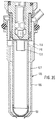
- FIG. 1 is a first exemplary embodiment Valve in the form of an injector for Fuel injection systems from mixture compressors spark-ignited internal combustion engines with a Atomizing sieve according to the invention partially shown.
- the injector has a tubular valve seat support 1, in which a valve axis 2 concentric Longitudinal opening 3 is formed.
- a valve axis 2 concentric Longitudinal opening 3 is formed.
- In the longitudinal opening 3 is a z.
- the injection valve is actuated in a known manner For example, electromagnetic.
- electromagnetic For axial Movement of the valve needle 5 and thus against opening the spring force of a return spring, not shown or closing the injection valve is an indicated electromagnetic circuit with a magnetic coil 10, one Anchor 11 and a core 12.
- the anchor 11 is with the Valve needle 5 connected and aligned with the core 12.
- the magnet coil 10 surrounds the core 12, which is the end of a not shown inlet port, the supply of Serves fuel represents.
- Valve seat body 16 To guide the valve closing body 7 during the A guide opening 15 serves for axial movement Valve seat body 16.
- the Core 11 facing away from the end of the valve seat support 1 is in the concentric to the valve along the longitudinal axis 2 Longitudinal opening 3 of the cylindrical valve seat body 16 tightly assembled by welding.
- in the central area 24 of the spray disk 21 are located at least one, for example four by eroding or Stamping molded injection openings 25.
- the insertion depth of the valve seat body 16 and pot-shaped spray plate 21 existing Valve seat part in the longitudinal opening 3 determines the Presetting the stroke of the valve needle 5, since one End position of the valve needle 5 when not energized Solenoid 10 by the valve closing body 7 on a valve seat surface 29 of the valve seat body 16 is set.
- the other end position of the valve needle 5 is when the solenoid 10 is excited, for example by the System of the anchor 11 set on the core 12. The way between these two end positions of the valve needle 5 thus represents the hub.
- the spherical valve closing body 7 interacts with the tapered in the direction of flow Valve seat surface 29 of the valve seat body 16 together, the in the axial direction between the guide opening 15 and the lower end face 17 of the valve seat body 16 is formed is. From a radial direction through the longitudinal opening 3 of the valve seat support 1 limited valve interior 35 the fuel enters the valve seat body 16 and flows in the guide opening 15 up to Valve seat surface 29. So that the flow of fuel also the spray openings 25 of the spray plate 21 reached, are on the circumference of the spherical valve closing body for example five flattenings 8 brought in. The five circular flats 8 allow the fuel to flow through in the open Condition of the injection valve from the valve interior 35 to the spray openings 25 of the spray plate 21st
- valve seat support 1 On the circumference of the valve seat support 1 is on his downstream, the solenoid 10 facing end one Protective cap 40 arranged and by means of, for example Snap connection connected to the valve seat support 1.
- a Sealing ring 41 serves to seal between the circumference of the Injector and one, not shown Valve holder, for example the intake line of the Internal combustion engine.
- atomizing sieve 50a Downstream of the orifice plate 21 is a arranged atomizing sieve 50a, the is arched out, for example, in the shape of a bowl, with one Bulge 51 seen in the flow direction of the fuel is provided concave. That preferably from one Stainless steel atomizing sieve 50a is made in Circumferential direction of a circumferential clamping ring 52 limited, in which the metallic fabric of the Atomizing screen 50a clamped, clamped or is encapsulated.
- the clamping ring 52 enables very simple assembly of the Atomizing sieve 50a, since the entire sieve arrangement is made of Atomizing sieve 50a and clamping ring 52 in one Method step between the valve seat support 1 and the Protective cap 40 can be clamped. This can be done either the atomizing sieve 50a with the clamping ring 52 with a Tool against the downstream end of the Valve seat support 1 pressed and the protective cap 40 over the clamping ring 52 onto the valve seat support 1 be pushed until the locking connection between Protective cap 40 and valve seat support 1 is made or the atomizing sieve 50a with the clamping ring 52 directly in an inner groove 53 of the protective cap 40 inserted and together attached to the valve seat support 1 with the protective cap 40 be, when reaching the locking connection between Protective cap 40 and valve seat support 1 of the clamping ring 52 completely between the downstream end of the Valve seat support 1 and the protective cap 40 is clamped.
- the collision or impact of the Fuel on the atomizing sieve 50a is a special one effective preparation method, in which atomization in particularly small droplets occur.
- the impact of the Fuel on the inner screen surface 55 has Consequence that the fuel is extremely slowed down and in each nearby meshes of the atomizing sieve 50a are deflected becomes.
- the collision on the atomizing sieve 50a alone causes tearing or dismemberment of the Fuel.
- the aim of this type of preparation is to be particularly fine atomized fuel in the form of tiny droplets from the Spray injector, for example, very much to achieve low exhaust emissions from the internal combustion engine and reduce fuel consumption.
- the Atomizing sieve 50a can meet precisely this requirement be fulfilled in a particularly advantageous manner.
- By the Tearing the fuel on the atomizing screen 50a and that Passing the fuel through the fine mesh of the Atomizing sieve 50a is created downstream of the Atomizing sieve 50a a fine droplet mist.
- This especially small fuel droplets forming the droplet mist now have a much larger one Surface than the fuel jets before hitting on the atomizing sieve 50a, which in turn for good Atomization is an indication.
- Embodiment of the atomizing sieve 50a and its The arrangement on the injection valve is the atomizing sieve 50a in the form of a bowl or a bowl in Flow direction of the fuel is concave.
- This concave bulge 51 of the atomizing sieve 50a provides that part of the fuel is directed towards a deepest region 56 of the convex atomizing sieve 50a can converge.
- the one in that middle deepest Area 56 collected fuel represents one each a relatively steady amount of fluid for a short time represents, then when the armature 11 or the valve needle is tightened 5 and the associated opening of Injector from the spray openings 25 of the Spray plate 21 leaking new fuel hits.
- the atomizing sieve 50a is in the for Shell edge or areas directed towards the clamping ring 52 only wetted continuously. A particularly high one The quality of atomization is thus due to the preparation directly on the mesh of the atomizing sieve 50a and by bouncing on the amount of liquid at rest Fuel through which the preparation in this middle Area 56 is achieved.
- This Minimum distance it can happen that the between the spray plate 21 and the Atomizing sieve 50a formed volume with too large Amount of fuel is filled and atomized no longer or only to a limited extent.
- the atomizing sieve 50a therefore arranged so that it is only downstream of the Valve seat support 1 between protective cap 40 and valve seat support 1 is pinched.
- the mesh size of the Atomizing sieve 50a has a crucial role decisively determines the spray quantity per unit of time.
- the atomizing sieve 50a forms itself a protective shield for the spray plate 21 Atomizing sieve 50a downstream of the orifice plate 21 namely the risk of icing, so-called Plugging and deposits of lead sulfate on the Spray plate 21 significantly reduced, as a result of which Intake manifold atmosphere from the spray openings 25 is kept away.
- the optimal Atomization has had achievable positive effects received in detail.
- the second embodiment shown in Figure 2 differs mainly from that in FIG. 1 illustrated embodiment by the shape of the Protective cap 40 and the attachment of the atomizing sieve 50b on the injector.
- the atomizing sieve 50b is also concave in the direction of flow arched and z. B. from a stainless metal manufactured.
- the metallic fabric for example, that in its outer radial peripheral region 60 similar to a plate edge is angled, exactly with this circumferential area 60 in poured the protective cap 40.
- the atomizing sieve 50b is similar to that Atomizing sieve 50a with a backstop in the Protective cap 40 embedded, d. H. the cap end 58 of the Protective cap 40 limits the injection valve downstream, while the deepest area 56 of the atomizing sieve 50b further upstream.
- the protective cap 40 is as a protective crown educated. Form away from the valve closing body 7 namely, for example, six protective tines 62 similar to one upside down crown the downstream end of the Injector.
- the number of protective tines can be 62 be designed variably, e.g. B. with two, four or six protective tines 62 on the protective cap 40.
- the protective cap 40 has in the form of a protective crown compared to a closed, all-round protective ring Advantages in the drip behavior of the injection valve.
- the Turbulence of fuel downstream of the atomizing screen 50b are weaker, which means less fuel than Wall film deposited on a protective cap inner wall 63.
- the slightly wetted protective cap 40 increases the risk drop formation significantly reduced.
- the atomizing sieve 50b in to pour a protective cap 40, which is only a one-piece, encircling protective ring.
- the atomizing sieve 50b in its Mesh size and its radius of curvature can be varied.
- the manufacturing cost of the atomizing sieves is 50 comparatively small, so that different Embodiments can be produced with little effort.
- a minimum distance between spray plate 21 and Atomizing sieve 50b is adhered to, resulting in a sufficiently large volume is created that the Hosing not completely filled with fuel can be. The minimum distance would be undershot noticeably reduce the quality of the atomization.
- FIG. 3 shows a third exemplary embodiment shown, in the downstream of the spray plate 21st in the protective cap 40, the atomizing sieve 50c as Double shell is poured.
- the atomizing sieve 50c So has in this case two in the direction of flow Fuel concave bulges 51, the Bulges 51 do not necessarily have a constant radius must have. As shown in Figure 3, the bowl-shaped bulges 51 in their deepest areas 56 also just be executed.
- the embodiments of the Bulges 51 of the atomizing sieve 50c are dependent on the tools for sieve deformation and can accordingly be influenced by these tools.
- thermoforming variant is the forming capacity of the screen fabric or the complexity and desired quality of the bulges 51 of the atomizing sieve 50 to be formed.
- the two bulges 51 of the atomizing sieve 50c are shaped such that with a spray orifice plate 21 with four spray orifices 25 each the fuel of two Spray openings 25 in a bulge 51 of the double shell of the atomizing sieve 50c. So the fuel will be atomized in two jet halves on the atomizing sieve 50c and processed.
- the bulges 51 can, for example, with each a circular or elliptical plane deepest area 56 or with a continuous Be radius of curvature.
- Figures 4 to 8 show schematic, not to scale Principle sketches of atomizing sieves 50 with one or several sieve arches and their assignment to the individual spray openings 25 of a spray orifice plate 21 with four spray orifices 25 Spray openings 25 of the spray plate 21 as spray openings 25 'projected onto the bulges 51 of the Atomizing screens 50 shown to prevent the spraying of the To clarify fuel on the atomizing sieves 50.
- the atomizing sieve shown schematically in FIG. 4 50b corresponds to that of the second one shown in FIG Embodiment.
- the fuel of all four Spray openings 25 of the spray disk 21 thus meet into a single bulge 51 of the atomizing sieve 50b, collides with the atomizing sieve 50b, partly runs into Direction of the deepest area 56 together and becomes optimal atomized.
- the atomizing sieve 50d in FIG. 5 has against four bulges 51, so that the fuel one each spray opening 25 in exactly one bulge 51 of the Atomizing sieve 50d aims. It is therefore possible to quartered fuel quantity to be processed.
- thermoforming tools are selected to the Forming atomizing sieve 50e exactly.
- engagement stamps of different sizes are also used in deep drawing Bulges 51 of different sizes achieved. That's the way it is for example possible, as can be seen in FIG. 7, two to create different bulges 51, wherein in a bulge 51 of the three spray openings 25 escaping fuel hits while in the second Bulge 51 only one jet of fuel Spray opening 25 is directed.
- the deep drawing tools can be used in such a way that a) a sieve web 65 remains between the two bulges 51 and so this spatially separates that b) touch both bulges 51 and thus merge when they are in the same axial depth that c) both bulges 51 touch a point, but not in the axial direction have the same extension or that d) both Partially overlap bulges 51.
- the atomizing sieve 50f is shown schematically in FIG shown that a circular and a distinguishes annular bulge 51. Radial from the outside the atomizing sieve 50f is also seen by the Limited peripheral area 60, which is ultimately in the Protective cap 40 is cast. Following inward closes the circumferential area 60 the circumferential annular Bulge 51 with the corresponding annular Thermoforming tools is easy to manufacture. To the middle one The area of the atomizing sieve 50f follows annular bulge 51 which is also annular Siebsteg 65, which is also the inner circular Bulge 51 limited to the outside. The circular Bulge 51 and the annular bulge 51 can in have different widths in the radial direction.
- both bulges 51 have, for example, in same height their deepest area 56, while the Siebsteg 65, for example, up to the exact height of Circumferential region 60 extends. Leave with this arrangement control different jet patterns.
- a Variant of this training is such that the sieve web 65, as shown in dashed lines in Figure 8, in the center of the atomizing sieve 50f and only one annular bulge 51 is surrounded so that a Cross section of the atomizing sieve 50f, which corresponds to the in corresponds to the atomizing sieve 50c shown in FIG. This results in a particularly favorable uniform fuel quantity distribution.
- FIG. 9 Another embodiment for the use of Atomizing sieve 50 according to the invention is shown in FIG. 9 shown.
- the atomizing sieve 50 is in the form of the Atomizing screen 50b, i.e. with a single in Direction of flow concave 51 designed.
- the outer peripheral region 60 of the Atomizing screen 50b is in turn in the protective cap 40 poured in, in an inwardly protruding Cap area 66, which is immediately downstream of the Valve seat support 1 bears against this.
- Inner cap region 66 four in the axial direction downstream, for example Protective tines 62 of the protective crown Protective cap 40.
- the four protective tines 62 are for example so arranged on the circumference of the protective cap 40 that they always have the same distance from each other, i.e.
- the separator 68a is positioned so that it is downstream of the deepest Area 56 of the atomizing screen 50b from a protective prong 62 to the one opposite, 180 ° away protective tines 62 lying across the valve longitudinal axis 2 runs and the one enclosed by the protective tines 62 Splashing area symmetrically.
- the at least two Spray openings 25 are also symmetrical to Separator 68a, so that at least one fuel jet right and at least one fuel jet left of the Separator 68a is directed.
- the assembly of the separator 68a on the protective tines 62 is very easy to For example by pressing, pouring or the like.
- Of the Divider 68a has the function of a desired double radiation of the injector, maintain or reinforce.
- FIG. 9 shows FIG. 10, with the beam splitter in the form and arrangement of that shown in Figure 9 Embodiment differs.
- the beam splitter is namely upstream of the atomizing screen 50b in the mold a separating cone 68b.
- the separation cone is 68b in the deepest area 56 of the atomizing sieve 50b arranged, the cone tip to Spray plate 21 extends out. It is both possible the beam splitter, for example the separating cone 68b, subsequently on the already manufactured and in the Protective cap 40 cast atomizing sieve 50b to set up as well as directly in the same process of Pouring in the atomizing sieve 50b.
- the conical beam splitter 68b can also be beam splitters with completely different cross-sectional shapes, for example as Tetrahedron, upstream and / or downstream on the Sieve surface 55 are used.
- the application too several cones is conceivable.
- beam splitters such as separators 68a and separating cone 68b to provide the asymmetrical in the injector run, i.e. not symmetrical to the valve longitudinal axis 2 are, and can even run axially inclined.
- This Arrangements are also based on, for example desired misalignment of the atomizing sieve 50b in Injector with respect to the valve longitudinal axis 2.
- FIG. 11 shows an injection valve for injection a fuel-gas mixture with one embodiment of the atomizing sieve 50 according to the invention
- downstream end of the valve seat support 1 is therefore from a stepped concentric gas containment body 70 at least partially enclosed radially and axially.
- Gas enclosing body 70 include a plastic for example the actual gas enclosure on downstream end of the valve seat support 1 as well Gas inlet channel, not shown, which the supply of Gases in the gas containment body 70 serves and for example in one piece with the gas enclosing body 70 is trained.
- the formation of the gas containment body 70 cannot one according to the spatial conditions shown valve holder can be varied.
- Gas enclosure body 70 with an axially extending tubular portion 71 formed.
- the axial section 71 surrounds the downstream end of the valve seat support 1 with a radial distance to the supply of the gas from the Spray openings 25 of the spray plate 21 emerging Fuel.
- the radial distance of the gas containment body 70 in section 71 has the result that an annular Gas inlet channel 72 between the valve seat support 1 and the Gas enclosure body 70 is formed.
- the axially extending section 71 has on its downstream end a radially outward circumferential shoulder 74, which arises from the fact that the outer periphery of the gas enclosing body 70 to form a Annular groove 75 is partially radially recessed.
- sealing ring 41 is used Seal between the circumference of the injector with the Gas enclosure body 70 and one, not shown Valve holder, for example the intake line of the Internal combustion engine or a so-called fuel and / or gas distribution line.
- a stepped insert 78 for example made of plastic with a radial Section 79 at several circumferential locations.
- a metering cross section ensure close to the axially extending Gas inlet channel 72, for example, three to six radial extending flow channels 80 between the radial extending section 79 of the insert part 78 and the downstream end face 76 of the valve seat support 1 after the assembly of the insert 78 or the Gas enclosure body 70 arise and radially from the gas be flowed through.
- Arrows in Figure 11 indicate axially upstream in one Annular channel 82 between a concentric, itself upstream frustoconical portion 83 of the insert part 78 and the wall of the longitudinal opening 3 in Valve seat support 1 until the flow is deflected at the Spray plate 21 in the radial direction.
- the gas enclosing body 70 presses with one of the Ring groove 75 in the direction of the valve longitudinal axis 2 inwards extending ring section 84 via a between Insert part 78 and gas containment body 70 inserted concentric and cup-shaped sleeve 86 which is fixed to the Valve seat support 1 is connected and thus for a Fixation of the insert part 78 with its radial section 79 provides against the radial section 79 of the insert 78, so that the inflowing gas only through openings 87 can enter the flow channels 80 in the sleeve 86 and a downstream escape between the gas containment body 70 and insert part 78 is excluded.
- Insert 78 With the aid of insert 78 and insert 78 at least partially engaging sleeve 86 ultimately the metering of the gas for improved Preparation of the from the spray orifices 25 Spray plate 21 leaking fuel.
- Insert 78 is centered and concentric with Longitudinal valve axis 2, for example a conical, widening mixture spray opening 89 brought in.
- the exact clamping of the insert part 78 results in a axial distance between the spray plate 21 and one of the spray plate 21 facing upper End face 90 of the insert part 78, that of the axial Expansion of a gas ring gap 91 formed thereby corresponds, fixed.
- the axial dimension of the Extension of the gas ring gap 91 forms the Metering cross section for the inflowing from the ring channel 82 Gas, for example treatment air.
- the gas ring gap 91 serves to supply the gas to the through the spray openings 25 delivered the spray plate 21 Fuel and gas metering.
- the supplied gas is greatly accelerated and atomizes the fuel particularly finely.
- a gas can for example by bypassing a throttle valve branched off in the intake manifold of the internal combustion engine Suction air, air conveyed by an additional fan, however also recirculated exhaust gas from the internal combustion engine or a Mixture of air and exhaust gas can be used.
- the mixture spray opening 89 in the insert part 78 has one such a large diameter that the upstream from the Spray openings 25 of the spray plate 21 emerging Fuel on which the gas is used for better processing coming vertically from the gas ring gap 91, unhindered by the mixture spray opening 89 of the Insert part 78 can emerge.
- the diameter of the Mixture spray opening 89 at the lower end of the insert 78 is provided for example as large as that largest diameter of the bulge 51 of the atomizing sieve 50g, which is exactly in the plane of the peripheral region 60 located.
- the bowl-shaped atomizing sieve is 50g again formed concave in the direction of flow and protrudes in the axial direction inside the gas containment body 70 with its deepest area 56, for example, up to Shoulder 74 of the gas containment body 70.
- Die das downstream end of the gas enclosing body 70 forming Shoulder 74 is also in this embodiment with its shoulder end 94, similar to the cap end 58 of the previous embodiments further downstream than the atomizing sieve 50g, so that protection against mechanical effects is guaranteed.
- FIG. 12 shows a subsequent atomizing sieve 50h, which can only be understood as a sketch.
- the Valve seat support 1 at its downstream end from the stepped concentric gas enclosing body 70 at least partially enclosed radially and axially.
- the axial Section 71 of the gas containment body 70 surrounds this downstream end of the valve seat support 1 with radial Distance to the supply of the gas, so that the annular Gas inlet channel 72 is formed.
- Downstream of the Spray plate 21 is inside the valve seat carrier 1 at least partially a stepped insert 78 ' arranged, for example in the longitudinal opening 3 on the clamped inner wall of the valve seat support 1 or is welded on.
- the axially extending Gas inlet channel 72 is an annular, radially extending Flow channel 80 to the radial between the lower extending section 79 of the insert part 78 'and downstream end face 76 of the valve seat support 1 after the assembly of the insert 78 'or Gas enclosure body 70 arises and radially from the gas is flowed through.
- the gas enclosing body 70 presses with the ring section 84 against the insert part 78 ', which in turn with its the Spray plate 21 facing the upper end face presses the spray plate 21 so that the insert 78 ' in addition to securing the position on the wall of the longitudinal opening 3 has an additional fixation.
- This also ensures that the gas coming from the gas inlet duct 72 only enters the space 96 via the flow channel 80.
- frustoconical section 83 of the Insert 78 ' are, for example, four obliquely radial extending supply channels 98 for the gas at the same distance to each other, i.e. after every 90 °.
- This Feed channels 98 connect the annular Room 96 with the center and concentric to Valve longitudinal axis 2 in the insert part 78 ', conical trained, expanding downstream Mixture spray opening 89.
- the recess 99 can now between Insert 78 'and insert 78 "the atomizing screen 50h can be clamped.
- the insert 78 " also has a center and Concentric to the longitudinal valve axis 2, the conicity of Mixture spray opening 89 continuing opening 100 in which the atomizing sieve 50h with its bulge 51 located. Between the two insert parts 78 'and 78 " is therefore only the peripheral region 60 of the Atomizing sieve clamped 50h.
- the supply channels 98 serve to supply the gas to the by the at least one, for example four Spray openings 25 of the spray orifice plate 21 are dispensed Fuel and gas metering.
- the supplied gas is accelerated in the feed channels 98 and strikes the fuel in the mixture spray opening 89.
- Die Feed channels 98 are aligned so that their imaginary extensions to the center of the Atomizing sieve 50h, i.e. in the deepest area 56 to meet. On the 56 collecting in the deepest area Fuel thus bounces out of the spray openings 25 escaping fuel, and also the gas flows precisely in this impact area.
- the fuel is consequently atomized particularly finely.
- the from the spray openings 25 escaping fuel jets can both directly into the Center of the atomizing screen 50h as well as parallel Fuel jets to areas outside of the deepest Area 56 or as divergent fuel jets on edge areas of the bulge 51 of the atomizing sieve 50h be directed.
- the gas supplied does not have to mandatory flow to the center of the atomizing sieve 50h, but can also go to other areas of bulge 51, for example to the impact areas of the fuel Atomizing sieve 50h.
- the Atomizing sieve 50h is for example with his Bulge 51 shaped so that it does not protrude downstream the insert parts 78 'and 78 "protrudes.
- the construction with two insert parts 78 'and 78 has the advantage that in a very short time an exchange of the atomizing sieves 50, for example in the form of the bulge or the Differentiate mesh size, can be made.
- FIG Another exemplary embodiment, which is shown in FIG is represented by a Atomizing sieve 50i downstream gas supply. Similar to the embodiment shown in Figure 2 the protective cap 40 is also provided here, which forms the downstream end of the injection valve.
- the protective cap 40 is attached, for example also via a snap connection on valve seat support 1, which is effective when the protective cap 40 with their circumferential inner cap region 66, in which also the Atomizing sieve 50i is cast in with its peripheral region 60 is on the downstream end face 76 of the Valve seat support 1 is present. That in the protective cap 40 cast-in atomizing sieve 50i is also curved in a bowl shape in the direction of flow and concave for example made of a rustproof metal.
- the atomizing sieve 50i is with a backstop in the Protective cap 40 embedded, i.e. the cap end 58 of the Protective cap 40 limits the injection valve downstream, while the deepest area 56 of the atomizing sieve 50i further upstream.
- the protective cap 40 is also in the form of a protective crown, the for example four axially extending protective tines 62 having. With a symmetrical arrangement of the Protective tines 62 are each 90 ° away from each other.
- the protective crown again offers the advantage an improved drip behavior of the injection valve.
- the protective cap 40 shown in Figure 13 The embodiment no longer forms a radial one Wall of the annular groove 75 for receiving the sealing ring 41, but partially limits the annular gas inlet channel 72 to supply the gas.
- the valve seat support 1 and the protective cap 40 namely at least partially of the tiered concentric gas enclosing body 70 radially and axially enclosed.
- the gas enclosure body 70 with the axially extending tubular portion 71 is formed.
- the axial section 71 surrounds an annular one Cap end part 102, with which the detent on the valve seat support 1 takes place and the protective tines 62 in the axial direction is exactly opposite, with a radial distance to the supply of Gas to the fuel atomized on the atomizing sieve 50i.
- the radial distance of the gas enclosing body 70 in Section 71 to the protective cap 40 has the consequence that the annular gas inlet channel 72 is formed.
- the axially extending section 71 has on its downstream end the radially outward-facing end Shoulder 74, which arises from the fact that the outer Scope of the gas enclosing body 70 to form the annular groove 75 partially recessed radially for the sealing ring 41 is formed, exactly in the axial extent wherever within the gas containment body 70 the Gas inlet channel 72 extends.
- the gas containment body 70 and the protective cap 40 are tight and tight together for example by welding or gluing in the area of Shoulder 74 connected. This ensures that no Gas between the gas containment body 70 and the protective cap 40 in the direction of the intake pipe of the internal combustion engine exit.
- the downstream end of gas inlet channel 72 begin to Atomizing sieve 50i are directed towards and on the Protective cap inner wall 63 on the spray plate 21 end facing away from the atomizing sieve 50i.
- Feed channels 98 ' are oriented so that their imaginary Extensions, preferably those of the center lines of the Feed channels 98 ', approximately in the center of the Atomizing screen 50i, that is, in the deepest area 56 of the Hit atomizing sieve 50i.
- Another way of Alignment of the feed channels 98 ' is that the imaginary extensions at exactly the places on the Atomizing sieve 50i, where the from the Spray openings 25 of the spray plate 21 coming Single fuel blasting onto the inner screen surface 55 the bulge 51 of the atomizing sieve 50i, which is, for example, a tangential touch.
- the gas flowing through the gas inlet channel 72 is in the Feed channels 98 'accelerate and then at least hit partially on the outer sieve surface of the arched Atomizing sieve 50i.
- the gas will hit the Atomizing sieve 50i swirled, partially occurs on the one hand to the inner screen surface 55 and on the other hand flows outside the atomizing sieve 50i towards deepest area 56 of the atomizing sieve 50i.
- the Feed channels 98 'can also be aligned so that the Gas only out downstream of the atomizing sieve 50i the fuel mist emerging from the atomizing sieve 50i meets.
- FIG. 14 the exemplary embodiment shown are the feed channels 98 ' formed as two pairs of channels, which are in their Differentiate cross-sectional size, whereby a gas supply with different intensity is achieved, which in turn a targeted spray pattern control of the fuel enables.
- Each channel pair is exactly two 180 ° opposite supply channels 98 'are formed, all Feed channels 98 'between each two projected Spray openings 25 'run.
- the channel pairs can not only in their cross-sectional size distinguish, but also in their cross-sectional shapes, for example circular, square or oval can.
- the arrows show the directions of flow of the gas and fuel.
- the two channel pairs are also completely in Asymmetrical circumferential direction in the protective cap 40 introduced feed channels 98 'replaceable, which also in their Inclination to the valve longitudinal axis 2 can be designed variably can.
- Another exemplary embodiment is shown in FIG shown, in which the feed channels 98 'so are aimed at that with imaginary extensions the projected spray openings 25 'or on the Collision points of the fuel on the atomizing sieve 50i to meet.
- One example is the inclination of the spray openings 25 of the spray plate 21 conical Fuel jet can through the feed channels 98 'for the Gas can be torn open in two fuel jets, so that the one existing directly on the atomizing sieve 50 single fuel jet into two fuel jets in is divided advantageously, for example each fuel jet is half the amount of fuel originally represents a single fuel jet.
- the Arrows at the projected spray openings 25 ' clarify that the fuel from the feed channels 98 ' is split away.
- FIG. 17 Another embodiment of a Fuel injection valve with the invention Atomizing sieve arrangement is shown in FIG. 17.
- the atomizing sieves 50i and 50j can, for example, with a constant distance to be largely parallel to each other.
- the Pouring the peripheral areas 60 into the protective cap 40 takes place, for example, in one process step.
- the atomizing screens 50i, 50j can be individually provided with clamping rings 52, e.g. shown in Figure 1, and stacked on top of each other or with the aid of insert parts 78, similar to those in FIG.
- the atomizing sieve 50 can be exemplary embodiments together with the protective cap 40 as a replaceable one Processing attachment used on the different types of injectors can be.
- the peripheral region 60 of the atomizing sieve 50i upstream and the peripheral region 60 of the Atomizing sieve 50j downstream of the feed channels 98 ' be provided so that the gas supply exactly between the two atomizing sieves 50i and 50j. No more illustrated embodiments result from the Variation of the fabric width, the number of Atomizing sieves 50 and the arrangement of the feed channels 98 ' with respect to the atomizing sieves 50.
- the feed channels 98 ' can be designed so that the gas downstream of the last atomizing sieve 50 and / or upstream of the first atomizing sieve 50 and / or flows between the two.
- FIGS. 18 and 19 illustrate possible examples Braiding types of atomizing sieves 50
- an atomizing sieve 50 is in the form of a perforated body shown over the entire surface has small holes or openings, the same or also have unequal cross-sectional sizes. That in Figure 23
- the atomizing sieve 50 shown has only longitudinal meshes, which are only on the edges by the extent of the Atomizing sieve 50 are limited. This design form is due to very tight wires z. B. made of stainless To reach metal. The advantages of these special sieve shapes are in addition to the very good atomization in the production completely new spray patterns.
- the atomizing sieves 50 can also be made of a semiconductor material, e.g. as Silicon chips, in the according to Figures 18 to 23 meshes or holes can be etched.
- Atomizing sieves are not shown in the figures, which are not perpendicular to the valve longitudinal axis 2 in Injector are installed, so an inclination to generate asymmetrical beam patterns or optimal in curved intake pipes of internal combustion engines to be able to inject.
- Embodiments are particularly characterized by that a clear spatial separation of metering and Processing of the fuel is provided, the constructively with an atomizer attachment 105 designated extension element is reached.
- the Atomizer attachment 105 consists largely of one sleeve-shaped, elongated spacer 106 and the seen in the direction of flow z.
- the goal is with the Atomizer attachment 105 when the Injector the point of fuel atomization in the ideal position in the air flow of the intake manifold To lay internal combustion engine so that a wall film formation of the To reduce or increase fuel in the intake manifold or manifold prevent, as a consequence a clear Reduction of exhaust emissions, especially the proportion of HC, is reached.
- the injection valve has part of a valve housing one extending at the downstream end Nozzle body 108, with the downstream end of the Nozzle body 108 represents the valve seat body 16.
- the nozzle body 108 is the stepped guide opening 15 formed, which is concentric with the valve longitudinal axis 2 runs and in which the valve needle 5 together with the Valve closing body 7 is arranged.
- the guide opening 15 of the nozzle body 108 has the Atomizer attachment 105 facing the end facing towards the frustoconical shape of the fuel flow Valve seat surface 29, which also with the frusto-conically tapering valve closing body 7 together forms a seat valve.
- Atomizer attachment 105 facing the lower end face 17 of the Nozzle body 108 rests on spray plate 21, which for example by means of laser welding produced weld seam firmly with the nozzle body 108 connected is.
- the spray plate 21 has z. Legs Spray opening 25 through which the lifted Valve closing body 7 on the valve seat surface 29 fuel flowing past into the atomizer attachment 105 is hosed.
- the sleeve-shaped spacer 106 is, for example graduated so that he as the valve seat body 16th designated end of the nozzle body 108 in the axial direction partially directly surrounding and z. B. also in small Dimensions by a radially extending shoulder 109 on the Spray plate 21 is present. Due to the cross section of the Spacer 106 reducing shoulder 109 results a diameter of the spacer 106 downstream of the Spray plate 21, which is smaller than the outer Diameter of the valve seat body 16 is. From the shoulder 109, the spacer 106 extends into the Intake pipe, not shown, into it, that is in the downstream Direction, for example with constant diameter.
- the injection valve In order to disturb the inner wall 110 of the To prevent spacer 106, the injection valve a narrow radial fuel jet with opening angle as small as possible, i.e. a so-called Cord jet, spray. With a one in the middle Spray opening 25 having spray plate 21 and the valve type shown in FIG. 24 can be such Cord rays can be generated, for example. Downstream the spray plate 21, but in the top facing it Part of the spacer 106 there are openings 111, the z. B. symmetrically on the circumference of the spacer 106 are arranged. Those entering through openings 111 Air jets are directed so that they do not hit the Aim atomization sieve 50. In particular, the Openings 111 closer to the spray opening 25 than at Atomizing sieve 50.
- the two to eight, for example Elongated holes, slots or circular holes allow formed openings 111 in the spacer 106 subsequently one inside the spacer 106 Air flow parallel to the fuel jet. Because of the fuel jet emerging from the spray opening 25 is namely intake manifold air through the openings 111 after the Principle of the water jet pump sucked in. This will make the otherwise in the spacer 106 downstream of the Injection orifice plate 21 resulting negative pressure and thus also the air backflow within the spacer 106 from Atomizing sieve 50 to the injection valve or the Swirling of the fuel jet avoided. A Backflow of air in the spacer 106 would become very disadvantageous wetting of the inner wall 110 with Lead fuel. The dripping of fuel the injector can now be switched off by this Measure largely prevented. That in Figure 24 The embodiment shown is particularly advantageous because the atomizer attachment 105 with the spacer 106 Due to its simple structure, it can be manufactured inexpensively and can be mounted on the injection valve and all desired Functions still fulfilled.
- FIGs 25, 26 and 27 show different exemplary embodiments of attached to spacers 106 Atomizing sieves 50, the figure 25 only one Enlargement of the atomizing sieve area from FIG. 24 represents.
- spacers 106 is expediently the atomizing sieve 50 made of plastic in the manufacturing process the injection molding of the spacer 106 directly with injected.
- materials used e.g. also metal
- Atomizing sieve 50 can also use other joining methods, such as Welding, soldering or gluing.
- FIGS. 26 and 27 Exemplary embodiments are shown in FIGS. 26 and 27 shown, in which the spacer 106 none constant diameter, but positive or negatively tapered, i.e. an expansion or Has taper towards the atomizing sieve 50.
- This Cross-sectional changes over the axial length of the Spacer 106 are possible at any time if a Impact of the fuel on the inner wall 110 is avoided.
- the atomizing sieve 50 can Forming the fuel spray to be sprayed into different geometric configurations with differently shaped bulges 51 are used, three of which are shown by way of example in FIGS. 25 to 27 are shown. According to the geometry of the Spacer 106 has the atomizing screen 50 z. B.
- a rather pointed bulge 51 ( Figure 26) or two bulges 51 through a central one inner screen web 65 are separated from one another (FIG. 27).
- the latter variant is particularly suitable for Spraying on two intake valves of the internal combustion engine on.
- the bulge 51st be annular, the inner sieve web 65th completely surrounds.
- the Metering takes place through the spray orifice plate 21 Preparation by means of the atomizing sieve 50.
- the fuel leaves the line at high speed metering spray plate 21 and is at typical Distances of 5 - 50 mm to the atomizing sieve 50 are not significantly braked or distracted so that the already described good treatment of the fuel by the Atomizing sieve 50 remains intact.
- the wide Limits adjustable spacer lengths can be the same Injector types for every internal combustion engine and each Suction pipe the ideal preparation position can be found.
- the consumption and emission-increasing cold start and Acceleration enrichment of fuel can same driving quality are greatly reduced because due to the atomizer attachment 105, the wall film formation is greatly reduced or even prevented in the intake manifold.
- FIG. 28 shows a further exemplary embodiment of a Injector shown that the in Figure 24 illustrated injector from the structure and technical Principle corresponds and that also an atomizer attachment 105, through which due to the spacer 106 with the atomizing sieve 50 according to the invention a clear spatial distance from the metering point is distant.
- the embodiment shown simply represents an experimental setup that mainly to explain the technical principle should serve and also constructively clearly can be performed differently from this arrangement.
- the atomizer attachment 105 is used in this Embodiment not only of the spacer 106 and the atomizing sieve 50, but also of a radially surrounding the valve seat body 16
- Gas introduction element 113 which is in the axial direction both upstream and downstream of the orifice plate 21 extends.
- the gas introduction element 113 stands out particularly characterized in that an annular gas supply from the at least one spray opening 25 escaping fuel in the spacer 106 is guaranteed.
- this gas supply looks like that Via a gas connection 115 outside air, which may be caused by Waste heat from the internal combustion engine or an active heater is heated, or exhaust in an upper annular Gas distributor 116 flows, from there via an axial one running narrow flow channel 117 parallel to Longitudinal valve axis 2 into a second lower, annular, e.g. B. downstream of the spray plate 21st lying gas distributor 118 passes from where the gas via, for example, inclined radial bores 119 enters the spacer 106 (gas introduction).
- the two gas distributors 116 and 118 are only optional intended.
- the gas introduction element 113 has two internal threads into which one side of the injector with one on the nozzle body 108 provided external thread and from the other side the spacer 106 are screwed so that the Gas introduction element 113 also as a connecting element between Injector and spacer 106 is used.
- This sleeve-shaped Spacer 106 is dimensioned (length, diameter) that the inner wall 110 is not from the fuel jet is wetted directly.
- the lower gas distributor 118 becomes Gas either through the radial bores 119 or through tubes or screens not shown so in the Spacer 106 initiated that a defined and stable gas flow arises.
- Part of the gas can also enter the atomizing sieve 50 facing part of the spacer on the intake manifold side 106 e.g. B. by a double wall, not shown here of the spacer 106 are placed so that the gas in the form of an atomization of the fuel improving (reducing droplet size) Gas containment works.
- the gas flow in the Spacer 106 bordered fuel jet is at Impact on the atomizing sieve 50 atomized. That through the atomizing sieve 50 flowing gas takes away any remaining Droplets of fuel with (blowing out the atomizing sieve 50) and thus leads to a significantly improved discharge and processing behavior, especially for small ones Press intake manifold.
- the fuel jet can supply gas before and after Preparation by the atomizing sieve 50 additionally be shaped (e.g. elliptical beam pattern, asymmetrical distribution of quantities).
- a Gas guide insert 120 may be provided, due to a axially extending sleeve 122 of the flow deflector and serves the axial outflow of the gas.
- the axial Sleeve 122 of the gas guide insert 120 goes to her upstream end z. B. in a radial Border area 123 over which is at least partially by the Spacer 106 pressed against the spray orifice plate 21 causing the gas routing insert 120 to slip is excluded.
- the gas routing insert 120 is in its length and its diameter are such that on the one hand, no wetting of the inner wall 110 the fuel emerging from the orifice plate 21 can occur and on the other hand that by the Radial bores 119 flowing gas is guided.
- the Atomizing sieve 50 can, in contrast to that in the Figures 24 to 27 illustrated embodiments in an outer recess 125 at the lower end of the Spacer 106 by z. B. gluing, welding or Snap into place or be cast on.
- the gas introduction element 113 shown in FIG. 28 it is possible to use the atomizing sieve 50 in one Distance of significantly more than 50 mm (e.g. up to 100 mm) to be arranged by the spray plate 21 and still the same positive effects as with the fuel injector Figure 24 to achieve.
- the fuel jet is due the gas flow is not slowed down or less. The one with it higher kinetic energy results in better atomization.
- hot gas e.g. B. exhaust gas
- hot gas by waste heat the engine heated air or by means of a electric auxiliary heating heated gas, it happens heating the atomizing sieve 50, the wall 110 of the spacer 106 and the fuel jet.
- the the evaporation of the fuel that results gives one additional improvement of processing.
- the atomizer attachment 105 of the one shown in FIG Embodiment is particularly characterized by that the spacer 106 is double-walled. Between the inner and outer walls of the Spacer 106 exist, for example, two semicircular, axially elongated spaces 127, the extend to the atomizing sieve 50 and directly downstream of the atomizing sieve 50 by exiting Gas provide a gas enclosure of the fuel so that a further reduction in droplet size and so improved atomization is achieved. Similar to Divider 68a in Figure 9 is inside the Spacer 106 a transverse to it, z. B. a beam cross-section having a circular cross section 68 upstream of the deepest area 56 of the Atomizing sieve 50 arranged.
- the beam splitter 68 with the function of the Tearing fuel in different directions can also have other cross-sections, not shown.
- the Figure 30 is a sectional view along the line XXX-XXX in Figure 29 and illustrates the course of the Beam splitter 68, for example in the between the Spaces 127 formed areas 128 of the Spacer 106 is attached. By varying the Dimensions (arc length, width) of the spaces 127 can ultimately the jet shapes of the fuel to be influenced.
- a gas inlet is provided, which already explained improvement in the discharge behavior of the Serves fuel.
- the atomizer attachment 105 is of this type formed that the inner wall of the spacer 106th not directly up to the spray perforated disk 21 approached, but rather a defined one Inflow ring gap 130 between itself and the Spray plate 21 forms. From the lower gas distributor 118, the gas can both axially into the spaces 127 and also largely radially directly into the inflow ring gap 130 flow in downstream of the orifice plate 21. The gas flowing through the inflow ring gap 130 ultimately a certain amount of gas in the fuel represents, however, only within the sleeve-shaped Spacer 106 acts and in addition to the Gas containment on the atomizing sieve 50 exists.
- the exemplary embodiment in FIGS. 31 and 32 differs from the fact that instead of Double walls of the spacer 106 and thereby formed gaps 127 for gas containment elongated, largely the length of the spacer 106 gas tube 131 directly on the inner Wall 110 is provided.
- gas tube 131 directly on the inner Wall 110 is provided.
- the gas is introduced again through the inflow ring gap 130 directly into the sleeve of the spacer 106, while this enables the gas to be enclosed on the atomizing sieve 50 is that from the gas distributor 118 first two to Longitudinal valve axis 2 inclined partial tubes 131 ' are formed that extend axially to Combine atomizing sieve 50 running gas tube 131.
- Figure 32 as a section along the line XXXII-XXXII in Figure 31 illustrates the course of the gas tube 131 close of the atomizing sieve 50.
- the gas tube 131 On the partial tubes 131 ' the gas tube 131 has a U-shaped end educated. It extends to the deepest Area 56 of the bulge 51 and arcuate on the opposite side to a small extent axially in Direction to the orifice plate 21 pointing upwards.
- This end region 132 of the gas tube 131 is closed and has an axial length that the axial extension a knife-shaped, flat, across the Bulge 51 of the atomizing sieve 50 extending Beam splitter 68 corresponds.
- the gas tube 131 In its deepest area 134 the gas tube 131 has outflow openings 135 for the gas on.
- the gas tube 131 is in the region of the bulge 51 of the Atomizing screen 50 in some way in the beam splitter 68 embedded.
- the one divided by the beam splitter 68 and among other things through the atomizing sieve 50 processed fuel is immediately downstream of the Atomizing screen 50 from that from the gas tube 131 escaping gas hit and particularly fine in the smallest Atomized droplets.
- the gas also has the effect of driving apart further by the beam splitter 68 given double radiation.
- Figures 33 and 34 illustrate only a little modified embodiment.
- the end portion 132 of the gas tube 131 is therefore horizontal or perpendicular to the valve longitudinal axis 2 executed, directly in the form of a Beam splitter 68.
- the gas tube 131 therefore, has a cross-sectional shape in its end region 132 has a triangular cross section, which enables beam splitting.
- the Spray side disk 21 is the end region 132 in turn designed so that 135 outflow openings Gas can flow downstream. In this case it serves that is already upstream of the atomizing sieve 50 with the Fuel contacting gas is more of improvement the discharge behavior of the fuel than that Reduction of the droplet size of the fuel.
- FIG Valve with spacer 106 and atomizing sieve 50 largely corresponds to the valve shown in FIG.
- This figure 35 is only intended to illustrate which Variety of variants by adding or leaving out individual small building blocks on the atomizer attachment 105 is possible. In the following, therefore, only those Differences to Figure 29 mentioned.
- the gas introduction takes place via the radial bores 119 as connections from lower gas distributor 118 and interior of the spacer 106. There is none in the area of the spray perforated disk 21 Inflow ring gap 130 provided, rather z. B. by installing the gas routing insert 120 Atomizer attachment 105 close to the spray plate 21 on. Gas also flows axially from gas distributor 118 between the two walls of the spacer 106 in Towards atomizing sieve 50. This arrangement can both be carried out with or without beam splitter 68.
- the atomizing sieve 50 facing end of the spacer 106 is one Venturi 137 provided.
- the Venturi nozzle 137 has the Task, before the atomization and preparation of the Fuel on the atomizing sieve 50 for a very good To mix fuel and gas. This in the Venturi nozzle 137 accelerated fuel-gas mixture increases the processing quality of the fuel.
- conical or pyramid-shaped Beam splitter 68 in the bulge 51 of the atomizing sieve 50 can optionally be arranged.
- Figure 38 shows a very simple form of training the Atomizer attachment 105.
- the main features of this Summarized exemplary embodiment are: none Gas introduction, but only sucking in intake manifold air the principle of the water jet pump through the openings 111 and thus pressure equalization with the environment and avoidance of wall wetting in the spacer 106; Beam splitter 68 web-like, for example, on the atomizing sieve 50 facing end of the spacer 106 across it fading.
- FIG. 41 The top view of a Atomizing sieve 50 with partial change in Mesh size, for example the same throughout Screen material is used, Figure 41 illustrates.
- the atomizing sieve 50 has a middle, web-like sieve area 139, which z. B. by the entire bulge 51 in a narrow strip extends.
- This inner sieve region 139 is surrounded both sides of outer screen areas 140, so that the Atomizing sieve 50 is formed from three segments. It is particularly advantageous to use the inner sieve region 139 coarser mesh than the outer sieve areas 140 to train.
- FIGs 42 and 43 are two other special cases a desired beam splitting of the fuel is shown.
- Internal combustion engine offers two separate, to use bowl-shaped atomizing sieves 50 (FIG 42), which is immediately at the downstream end of the Spacer 106 attached and from each other by the Beam splitters 68 are separated.
- the beam splitter 68 goes thereby directly from the wall of the spacer 106 and thus also gives the required stability in the Area of atomizing sieves 50.
- Spacer 106 is in the embodiment in Figure 43 a mainly downstream of the Atomizing sieve 50 extending with the spacer 106 firmly connected, sleeve-shaped beam splitting element 141 arranged.
- the beam splitting element 141 has again at its downstream end the actual e.g. B. cutting beam splitter 68 on it has a clear distance from the atomizing sieve 50.
- the length of the beam splitting element 141 can be corresponding the installation conditions and the geometry of the intake manifold can be variably designed and optimally adapted.
- the one Atomizing sieve 50 downstream beam splitter 68 provides for the fact that the already atomized and processed Fuel spray in different directions (e.g. two Inlet valves) is sprayed. This arrangement is Can be combined with a gas inlet at any time.
- the valve shown in Figure 44 with the Atomizer attachment 105 is particularly characterized by the Spacer 106 built-in Venturi 137 from is already known from FIG. 37.
- the venturi 137 is now arranged so that according to the Water jet pump principle sucked intake manifold air over the Openings 111 immediately at the narrowest point of the Venturi nozzle 137 flows.
- This Nozzle insert body 143 is, for example, in the Spacer 106 is pressed. According to the number of Openings 111 are e.g. B.
Landscapes
- Engineering & Computer Science (AREA)
- Chemical & Material Sciences (AREA)
- Combustion & Propulsion (AREA)
- Mechanical Engineering (AREA)
- General Engineering & Computer Science (AREA)
- Fuel-Injection Apparatus (AREA)
Description
Claims (34)
- Brennstoffeinspritzventil zur Versorgung einer Brennkraftmaschine mit Brennstoff bzw. mit einem Brennstoff-Gas-Gemisch, mit einer Ventillängsachse (2), mit einem Ventilschließteil (7), das mit einer Ventilsitzfläche (29) zusammenwirkt, mit wenigstens einer Abspritzöffnung (25) und mit einem stromabwärts der wenigstens einen Abspritzöffnung (25) am Brennstoffeinspritzventil angeordneten Zerstäubungssieb (50, 50a-j) mit einem Siebblatt, dadurch gekennzeichnet, daß das Zerstäubungssieb (50, 50a-j) wenigstens ein gewebeartiges oder geflechtartiges oder maschenförmiges oder netzartiges oder gitterartiges oder über die gesamte Fläche viellöchriges Siebblatt hat, das eine von einer ebenen Blattform abweichende Gestalt besitzt.
- Brennstoffeinspritzventil nach Anspruch 1, dadurch gekennzeichnet, daß das Zerstäubungssieb (50) schalenförmig gewölbt ausgebildet ist.
- Brennstoffeinspritzventil nach Anspruch 2, dadurch gekennzeichnet, daß das Zerstäubungssieb (50) mehr als eine schalenförmige Auswölbung (51) besitzt.
- Brennstoffeinspritzventil nach Anspruch 1, dadurch gekennzeichnet, daß das Zerstäubungssieb (50) aus rostfreiem Metall, Kunststoff, Teflon, PTC-Material oder Silizium gefertigt ist.
- Brennstoffeinspritzventil nach Anspruch 1, dadurch gekennzeichnet, daß das Siebblatt des Zerstäubungssiebs (50) eine Maschenweite von >= 0,1 mm aufweist.
- Brennstoffeinspritzventil nach Anspruch 1, dadurch gekennzeichnet, daß das Zerstäubungssieb (50) ein- oder mehrlagig ausgeführt ist.
- Brennstoffeinspritzventil nach Anspruch 5, dadurch gekennzeichnet, daß die Maschenweite des Siebblattes des Zerstäubungssiebes (50) nicht konstant ist.
- Brennstoffeinspritzventil nach Anspruch 1, dadurch gekennzeichnet, daß das Zerstäubungssieb (50) aus Bimetall ausgebildet ist.
- Brennstoffeinspritzventil nach einem der vorhergehenden Ansprüche, dadurch gekennzeichnet, daß das Zerstäubungssieb (50) am Umfang zumindest teilweise in einem Klemmring (52) angeordnet ist, der zwischen einem Ventilsitzträger (1) und einer am Ventilsitzträger (1) des Brennstoffeinspritzventils angebrachten Schutzkappe (40) eingespannt ist.
- Brennstoffeinspritzventil nach einem der Ansprüche 1 bis 8, dadurch gekennzeichnet, daß das Zerstäubungssieb (50) mit einem Umfangsbereich (60) in einer am stromabwärtigen Ende des Brennstoffeinspritzventils angebrachten Schutzkappe (40) eingegossen ist.
- Brennstoffeinspritzventil nach Anspruch 9 oder 10, dadurch gekennzeichnet, daß die Schutzkappe (40) die Form einer Schutzkrone mit vom Brennstoffeinspritzventil abgewandt gerichteten Schutzzinken (62) hat.
- Brennstoffeinspritzventil nach Anspruch 11, dadurch gekennzeichnet, daß die Schutzzinken (62) der Schutzkappe (40) weiter stromabwärts ragen als ein tiefster Bereich (56) des Zerstäubungssiebes (50).
- Brennstoffeinspritzventil nach Anspruch 3, dadurch gekennzeichnet, daß das Zerstäubungssieb (50) mindestens zwei Auswölbungen (51) besitzt, die symmetrisch zur Ventillängsachse (2) angeordnet sind.
- Brennstoffeinspritzventil nach Anspruch 3, dadurch gekennzeichnet, daß das Zerstäubungssieb (50) mindestens zwei Auswölbungen (51) besitzt, die asymmetrisch zur Ventillängsachse (2) angeordnet sind.
- Brennstoffeinspritzventil nach Anspruch 1, dadurch gekennzeichnet, daß das Zerstäubungssieb (50) wenigstens eine Auswölbung (51) besitzt, die ringförmig ausgebildet ist.
- Brennstoffeinspritzventil nach Anspruch 1, dadurch gekennzeichnet, daß am Zerstäubungssieb (50) an dessen stromaufwärtiger und/oder stromabwärtiger Oberfläche (55) ein Strahlteiler (68) integriert ist.
- Brennstoffeinspritzventil nach Anspruch 1, dadurch gekennzeichnet, daß stromabwärts des Zerstäubungssiebs (50) ein Strahlteiler (68) verläuft.
- Brennstoffeinspritzventil nach Anspruch 1, dadurch gekennzeichnet, daß zwischen der wenigstens einen Abspritzöffnung (25) und dem wenigstens einen Zerstäubungssieb (50) ein Gasringspalt (91) vorgesehen ist und der aus der wenigstens einen Abspritzöffnung (25) austretende Brennstoff mit dem aus dem Gasringspalt (91) austretenden Gas kollidiert, so daß ein Brennstoff-Gas-Gemisch auf das Zerstäubungssieb (50) trifft.
- Brennstoffeinspritzventil nach Anspruch 1, dadurch gekennzeichnet, daß zwischen der wenigstens einen Abspritzöffnung (25) und dem wenigstens einen Zerstäubungssieb (50) in einem in einen Ventilsitzträger (1) ragenden Einsatzteil (78') Zuführkanäle (98) ausgebildet sind, über die ein Gas zuführbar ist und der aus der wenigstens einen Abspritzöffnung (25) austretende Brennstoff mit dem aus den Zuführkanälen (98) austretenden Gas kollidiert, so daß ein Brennstoff-Gas-Gemisch auf das Zerstäubungssieb (50) trifft.
- Brennstoffeinspritzventil nach Anspruch 1, dadurch gekennzeichnet, daß Zuführkanäle (98') für ein Gas so am Brennstoffeinspritzventil angeordnet sind, daß sie auf der der wenigstens einen Abspritzöffnung (25) abgewandten Seite des Zerstäubungssiebs (50) enden.
- Brennstoffeinspritzventil nach Anspruch 20, dadurch gekennzeichnet, daß die Zuführkanäle (98') so ausgerichtet sind, daß ihre gedachten Verlängerungen auf einen tiefsten Bereich (56) des Zerstäubungssiebs (50) zielen.
- Brennstoffeinspritzventil nach Anspruch 20, dadurch gekennzeichnet, daß die Zuführkanäle (98') so ausgerichtet sind, daß ihre gedachten Verlängerungen tangential die Oberfläche des Zerstäubungssiebs (50) berühren.
- Brennstoffeinspritzventil nach Anspruch 1, dadurch gekennzeichnet, daß wenigstens zwei hintereinander geschaltete Zerstäubungssiebe (50) am Brennstoffeinspritzventil befestigt sind.
- Brennstoffeinspritzventil nach Anspruch 9 oder 10, dadurch gekennzeichnet, daß das Zerstäubungssieb (50) zusammen mit der Schutzkappe (40) einen auswechselbaren Aufbereitungsvorsatz bildet.
- Brennstoffeinspritzventil nach Anspruch 1, dadurch gekennzeichnet, daß zwischen der wenigstens einen Abspritzöffnung (25) und dem wenigstens einen Zerstäubungssieb (50) ein Abstandskörper (106) so angeordnet ist, daß eine deutliche räumliche Trennung von Zumessung im Bereich der wenigstens einen Abspritzöffnung (25) und Aufbereitung im Bereich des Zerstäubungssiebs (50) vorhanden ist.
- Brennstoffeinspritzventil nach Anspruch 25, dadurch gekennzeichnet, daß der Abstandskörper (106) zusammen mit dem Zerstäubungssieb (50) einen Zerstäubervorsatz (105) bildet.
- Brennstoffeinspritzventil nach Anspruch 25, dadurch gekennzeichnet, daß das Zerstäubungssieb (50) in einer Entfernung von 5 bis 100 mm von der wenigstens einen Abspritzöffnung (25) angeordnet ist.
- Brennstoffeinspritzventil nach Anspruch 25, dadurch gekennzeichnet, daß der Abstandskörper (106) hülsenförmig ausgeführt ist und auf seiner der wenigstens einen Abspritzöffnung (25) zugewandten Seite Öffnungen (111) zum Einsaugen eines Gases besitzt.
- Brennstoffeinspritzventil nach Anspruch 25, dadurch gekennzeichnet, daß der Abstandskörper (106) zumindest über den größten Teil seines Umfangs doppelwandig ausgebildet ist und zwischen den zwei Wänden Zwischenräume (127) vorgesehen sind, durch die ein Gas strömen kann.
- Brennstoffeinspritzventil nach Anspruch 25, dadurch gekennzeichnet, daß im Abstandskörper (106) ein Strahlteiler (68) integriert ist.
- Brennstoffeinspritzventil nach Anspruch 25, dadurch gekennzeichnet, daß im Abstandskörper (106) eine einen geringeren Querschnitt als der Abstandskörper (106) aufweisende Gasröhre (131) weitgehend axial verläuft, die erst nahe des Zerstäubungssiebs (50) Ausströmöffnungen (135) aufweist.
- Brennstoffeinspritzventil nach Anspruch 25, dadurch gekennzeichnet, daß im Inneren des Abstandskörpers (106) eine Venturidüse (137) mit einer Querschnittsverringerung gegenüber dem Abstandskörper (106) vorgesehen ist.
- Brennstoffeinspritzventil nach Anspruch 25, dadurch gekennzeichnet, daß im Inneren des Abstandskörpers (106) stromabwärts der wenigstens einen Abspritzöffnung (25) ein Gasführungseinsatz (120) angeordnet ist, der wenigstens eine weitgehend axial verlaufende Abströmfläche für ein Gas besitzt.
- Brennstoffeinspritzventil nach Anspruch 25, dadurch gekennzeichnet, daß stromabwärts der wenigstens einen Abspritzöffnung (25) durch die Geometrie des Abstandskörpers (106) ein definierter Zuströmringspalt (130) zum Einströmen eines Gases gebildet ist.
Applications Claiming Priority (5)
| Application Number | Priority Date | Filing Date | Title |
|---|---|---|---|
| DE4343688 | 1993-12-21 | ||
| DE4343688 | 1993-12-21 | ||
| DE4442350 | 1994-11-29 | ||
| DE4442350A DE4442350A1 (de) | 1993-12-21 | 1994-11-29 | Zerstäubungssieb und Brennstoffeinspritzventil mit einem Zerstäubungssieb |
| PCT/DE1994/001510 WO1995017595A1 (de) | 1993-12-21 | 1994-12-20 | Zerstäubungssieb und brennstoffeinspritzventil mit einem zerstäubungssieb |
Publications (2)
| Publication Number | Publication Date |
|---|---|
| EP0694124A1 EP0694124A1 (de) | 1996-01-31 |
| EP0694124B1 true EP0694124B1 (de) | 1999-03-17 |
Family
ID=25932302
Family Applications (1)
| Application Number | Title | Priority Date | Filing Date |
|---|---|---|---|
| EP95903245A Expired - Lifetime EP0694124B1 (de) | 1993-12-21 | 1994-12-20 | Zerstäubungssieb und brennstoffeinspritzventil mit einem zerstäubungssieb |
Country Status (8)
| Country | Link |
|---|---|
| US (1) | US5707012A (de) |
| EP (1) | EP0694124B1 (de) |
| JP (1) | JP3512807B2 (de) |
| CN (1) | CN1050649C (de) |
| BR (1) | BR9406147A (de) |
| DE (1) | DE59407970D1 (de) |
| ES (1) | ES2131299T3 (de) |
| WO (1) | WO1995017595A1 (de) |
Cited By (2)
| Publication number | Priority date | Publication date | Assignee | Title |
|---|---|---|---|---|
| EP4390109A1 (de) | 2022-12-23 | 2024-06-26 | DEUTZ Aktiengesellschaft | Zylinderkopf für eine brennkraftmaschine und eine brennkraftmaschine mit einem solchen zylinderkopf |
| EP4394173A1 (de) | 2022-12-23 | 2024-07-03 | DEUTZ Aktiengesellschaft | Zylinderkopf für eine brennkraftmaschine und eine brennkraftmaschine mit einem solchen zylinderkopf |
Families Citing this family (31)
| Publication number | Priority date | Publication date | Assignee | Title |
|---|---|---|---|---|
| DE19505886A1 (de) * | 1995-02-21 | 1996-08-22 | Bosch Gmbh Robert | Vorrichtung zur Einspritzung eines Brennstoff-Gas-Gemisches |
| US5967424A (en) * | 1998-06-24 | 1999-10-19 | General Motors Corporation | Fuel injector filter |
| DE10032330A1 (de) * | 2000-07-04 | 2002-01-17 | Bosch Gmbh Robert | Brennstoffeinspritzsystem |
| DE10118163B4 (de) * | 2001-04-11 | 2007-04-19 | Robert Bosch Gmbh | Brennstoffeinspritzventil |
| DE10130206A1 (de) * | 2001-06-22 | 2003-02-06 | Bosch Gmbh Robert | Brennstoffeinspritzventil |
| DE10130685A1 (de) * | 2001-06-26 | 2003-01-02 | Bosch Gmbh Robert | Brennstoffeinspritzventil |
| EP1581737B1 (de) * | 2003-01-09 | 2009-05-27 | Continental Automotive Systems US, Inc. | Sprühmustersteuerung mit an einer einen beutelvolumenreduzierer aufweisenden, mit vertiefungen versehenen kraftstoffeinspritzdosierscheibe ausgebildeten nicht abgewinkelten öffnungen |
| JP4021405B2 (ja) * | 2003-12-10 | 2007-12-12 | 株式会社日立製作所 | 燃料噴射弁 |
| US7412972B2 (en) * | 2004-03-04 | 2008-08-19 | Continental Automotive Systems Us, Inc. | Dispersion-type suppressor for acoustic noise reduction of a gaseous fuel injector |
| TWI281691B (en) * | 2004-08-23 | 2007-05-21 | Ind Tech Res Inst | Method for manufacturing a quantum-dot element |
| US7617991B2 (en) * | 2006-03-31 | 2009-11-17 | Delphi Technologies, Inc. | Injector fuel filter with built-in orifice for flow restriction |
| USD576874S1 (en) | 2007-08-24 | 2008-09-16 | S.C. Johnson & Son, Inc | Actuator cap |
| US8820665B2 (en) | 2007-09-25 | 2014-09-02 | S.C. Johnson & Son, Inc. | Fluid dispensing nozzle |
| NL2002079C (nl) * | 2008-10-10 | 2010-04-13 | Univ Eindhoven Tech | Brandstofinjector voor een verbrandingsmotor. |
| WO2012086006A1 (ja) * | 2010-12-20 | 2012-06-28 | トヨタ自動車株式会社 | 燃料噴射弁 |
| DE102010064268A1 (de) | 2010-12-28 | 2012-06-28 | Robert Bosch Gmbh | Einspritzventil |
| JP5811979B2 (ja) * | 2012-09-24 | 2015-11-11 | 株式会社デンソー | 燃料噴射弁 |
| US20140116391A1 (en) * | 2012-10-31 | 2014-05-01 | Electro-Motive Diesel, Inc. | Fuel system having an injector blocking member |
| US9856836B2 (en) | 2015-06-25 | 2018-01-02 | Woodward, Inc. | Variable fluid flow apparatus with integrated filter |
| DE102015226769A1 (de) * | 2015-12-29 | 2017-06-29 | Robert Bosch Gmbh | Brennstoffeinspritzventil |
| EP3267027A1 (de) * | 2016-07-07 | 2018-01-10 | Winterthur Gas & Diesel AG | Düsenkopf für eine brennstoffeinspritzdüse eines grossdieselmotors, sowie verfahren zum herstellen eines solchen |
| DE102016222908A1 (de) | 2016-11-21 | 2018-05-24 | Robert Bosch Gmbh | Injektor mit dreiteiligem Ventilsitz |
| CN106837639A (zh) * | 2017-04-13 | 2017-06-13 | 沈阳航空航天大学 | 一种近距离碰撞式双燃料发动机喷嘴组件 |
| US10927804B2 (en) | 2017-06-07 | 2021-02-23 | Ford Global Technologies, Llc | Direct fuel injector |
| US10823127B2 (en) | 2018-03-14 | 2020-11-03 | Ford Global Technologies, Llc | Methods and systems for a fuel injector |
| US11045776B2 (en) | 2018-08-22 | 2021-06-29 | Ford Global Technologies, Llc | Methods and systems for a fuel injector |
| CN109882330A (zh) * | 2019-03-19 | 2019-06-14 | 重庆喜恩动力机械有限公司 | 柴油机一体化油泵油嘴独立喷油结构 |
| US20230025671A1 (en) * | 2021-07-19 | 2023-01-26 | Moran Motorsports Inc. | System of Using a Flow Disc to Modify a Spray Pattern of a Fuel Injector |
| CN115137114B (zh) * | 2022-06-10 | 2025-08-12 | 太原科技大学 | 一种基于热电材料Peltier效应的智能空调服 |
| CN116237176B (zh) * | 2023-05-11 | 2023-07-25 | 四川工程职业技术学院 | 一种内置雾化装置及内置雾化方法 |
| DE102024102103A1 (de) * | 2024-01-25 | 2025-07-31 | Heinzmann Gmbh & Co. Kg | Kraftstoff-Injektor, insbesondere zum Zerstäuben von Methanol, sowie zugehörige Maschine, Verfahren und Verwendungen |
Family Cites Families (16)
| Publication number | Priority date | Publication date | Assignee | Title |
|---|---|---|---|---|
| US460368A (en) * | 1891-09-29 | Sprinkler | ||
| FR699734A (fr) * | 1929-08-03 | 1931-02-19 | Perfectionnements aux atomiseurs de combustible pour moteurs à combustion interne | |
| US2541854A (en) * | 1948-09-22 | 1951-02-13 | Chicago Specialty Mfg Co Inc | Water aerating device |
| US2618511A (en) * | 1949-03-18 | 1952-11-18 | Spraying Systems Co | Stirrup nozzle |
| DE828329C (de) * | 1949-07-13 | 1952-01-17 | Jean Tilliet | Vorrichtung zur Betaetigung des Verschlussorgans von Brennstoffinjektoren fuer Waermekraftmaschinen |
| US2829874A (en) * | 1954-05-04 | 1958-04-08 | Rockwood Sprinkler Co | Foam generating apparatus |
| US2929567A (en) * | 1957-02-12 | 1960-03-22 | Elie P Aghnides | Liquid and gas mixing device |
| DE2306362A1 (de) * | 1973-02-09 | 1974-08-15 | Bosch Gmbh Robert | Einrichtung zur kraftstoffaufbereitung bei fremdgezuendeten brennkraftmaschinen |
| US4057190A (en) * | 1976-06-17 | 1977-11-08 | Bendix Corporation | Fuel break-up disc for injection valve |
| US4646974A (en) * | 1985-05-06 | 1987-03-03 | General Motors Corporation | Electromagnetic fuel injector with orifice director plate |
| GB8611950D0 (en) * | 1986-05-16 | 1986-06-25 | Lucas Ind Plc | Gasoline injector |
| GB8718391D0 (en) * | 1987-08-04 | 1987-09-09 | Lucas Elect Electron Syst | Fuel injector |
| JPH0318662A (ja) * | 1989-05-29 | 1991-01-28 | Aisan Ind Co Ltd | 電磁式燃料噴射弁のノズル構造 |
| US5174505A (en) * | 1991-11-01 | 1992-12-29 | Siemens Automotive L.P. | Air assist atomizer for fuel injector |
| EP0629266B1 (de) * | 1992-03-05 | 1996-12-18 | Siemens Automotive Corporation | Brennstoffeinspritzdüse mit internen filter |
| DE4312756A1 (de) * | 1993-04-20 | 1994-10-27 | Bosch Gmbh Robert | Vorrichtung zur Einspritzung eines Brennstoff-Gas-Gemisches |
-
1994
- 1994-12-20 DE DE59407970T patent/DE59407970D1/de not_active Expired - Fee Related
- 1994-12-20 JP JP51708995A patent/JP3512807B2/ja not_active Expired - Fee Related
- 1994-12-20 WO PCT/DE1994/001510 patent/WO1995017595A1/de not_active Ceased
- 1994-12-20 US US08/505,295 patent/US5707012A/en not_active Expired - Fee Related
- 1994-12-20 ES ES95903245T patent/ES2131299T3/es not_active Expired - Lifetime
- 1994-12-20 CN CN94191240A patent/CN1050649C/zh not_active Expired - Fee Related
- 1994-12-20 EP EP95903245A patent/EP0694124B1/de not_active Expired - Lifetime
- 1994-12-20 BR BR9406147A patent/BR9406147A/pt not_active IP Right Cessation
Cited By (5)
| Publication number | Priority date | Publication date | Assignee | Title |
|---|---|---|---|---|
| EP4390109A1 (de) | 2022-12-23 | 2024-06-26 | DEUTZ Aktiengesellschaft | Zylinderkopf für eine brennkraftmaschine und eine brennkraftmaschine mit einem solchen zylinderkopf |
| EP4394173A1 (de) | 2022-12-23 | 2024-07-03 | DEUTZ Aktiengesellschaft | Zylinderkopf für eine brennkraftmaschine und eine brennkraftmaschine mit einem solchen zylinderkopf |
| DE102022004896A1 (de) | 2022-12-23 | 2024-07-04 | Deutz Aktiengesellschaft | Zylinderkopf für eine Brennkraftmaschine und eine Brennkraftmaschine mit einem solchen Zylinderkopf |
| DE102022004897A1 (de) | 2022-12-23 | 2024-07-04 | Deutz Aktiengesellschaft | Zylinderkopf für eine Brennkraftmaschine und eine Brennkraftmaschine mit einem solchen Zylinderkopf |
| US12442351B2 (en) | 2022-12-23 | 2025-10-14 | Deutz Aktiengesellschaft | Cylinder head for an internal combustion engine and an internal combustion engine with such a cylinder head |
Also Published As
| Publication number | Publication date |
|---|---|
| DE59407970D1 (de) | 1999-04-22 |
| JPH08507118A (ja) | 1996-07-30 |
| US5707012A (en) | 1998-01-13 |
| CN1050649C (zh) | 2000-03-22 |
| ES2131299T3 (es) | 1999-07-16 |
| EP0694124A1 (de) | 1996-01-31 |
| BR9406147A (pt) | 1996-02-13 |
| WO1995017595A1 (de) | 1995-06-29 |
| JP3512807B2 (ja) | 2004-03-31 |
| CN1118181A (zh) | 1996-03-06 |
Similar Documents
| Publication | Publication Date | Title |
|---|---|---|
| EP0694124B1 (de) | Zerstäubungssieb und brennstoffeinspritzventil mit einem zerstäubungssieb | |
| DE19638201B4 (de) | Brennstoffeinspritzventil | |
| DE69805967T2 (de) | Drallerzeuger für kraftstoffeinspritzventil | |
| EP0846225B1 (de) | Einspritzventil, insbesondere zum direkten einspritzen von kraftstoff in einen brennraum eines verbrennungsmotors | |
| EP1073838B1 (de) | Brennstoffeinspritzventil | |
| DE3229716C2 (de) | Kraftstoffeinspritzvorrichtung | |
| DE102004005526B4 (de) | Kraftstoffeinspritzvorrichtung einer Brennkraftmaschine mit innerer Verbrennung | |
| EP0515810B1 (de) | Vorrichtung zur Einspritzung eines Brennstoff-Gas-Gemisches | |
| DE60202951T2 (de) | Formung des einspritzstrahls mit nicht-schrägen öffnungen in der einspritzdüsenscheibe | |
| DE69718325T2 (de) | Verfahren und vorrichtung zur kontrollierten zerstäubung für ein kraftstoffeinspritzventil eines verbrennungsmotor | |
| EP1208298A1 (de) | Brennstoffeinspritzventil und verfahren zur herstellung von austrittsöffnungen an ventilen | |
| DE4129834A1 (de) | Vorrichtung zur einspritzung eines brennstoff-gas-gemisches | |
| EP0646219B1 (de) | Vorrichtung zur einspritzung eines brennstoff-gas-gemisches | |
| EP1073837A1 (de) | Brennstoffeinspritzventil | |
| EP0859910A1 (de) | Ventil, insbesondere brennstoffeinspritzventil | |
| DE19636396A1 (de) | Brennstoffeinspritzventil | |
| DE4442350A1 (de) | Zerstäubungssieb und Brennstoffeinspritzventil mit einem Zerstäubungssieb | |
| EP2064438A1 (de) | Brennstoffeinspritzventil | |
| EP0728942B1 (de) | Vorrichtung zur Einspritzung eines Brennstoff-Gas-Gemisches | |
| DE4415992A1 (de) | Brennstoffeinspritzventil | |
| DE69809197T2 (de) | Pneumatisch unterstützte brennstoffeinspritzdüse | |
| EP0844386B1 (de) | Vorrichtung zur Einspritzung eines Brennstoff-Gas-Gemisches | |
| WO1992014052A1 (de) | Vorrichtung zur einspritzung eines brennstoff-gas-gemisches | |
| WO1992003651A1 (de) | Brennstoffeinspritzventil | |
| DE102004050223A1 (de) | Brennstoffeinspritzventil |
Legal Events
| Date | Code | Title | Description |
|---|---|---|---|
| PUAI | Public reference made under article 153(3) epc to a published international application that has entered the european phase |
Free format text: ORIGINAL CODE: 0009012 |
|
| AK | Designated contracting states |
Kind code of ref document: A1 Designated state(s): DE ES FR GB IT SE |
|
| 17P | Request for examination filed |
Effective date: 19951229 |
|
| 17Q | First examination report despatched |
Effective date: 19970513 |
|
| GRAG | Despatch of communication of intention to grant |
Free format text: ORIGINAL CODE: EPIDOS AGRA |
|
| GRAG | Despatch of communication of intention to grant |
Free format text: ORIGINAL CODE: EPIDOS AGRA |
|
| GRAH | Despatch of communication of intention to grant a patent |
Free format text: ORIGINAL CODE: EPIDOS IGRA |
|
| GRAH | Despatch of communication of intention to grant a patent |
Free format text: ORIGINAL CODE: EPIDOS IGRA |
|
| GRAA | (expected) grant |
Free format text: ORIGINAL CODE: 0009210 |
|
| AK | Designated contracting states |
Kind code of ref document: B1 Designated state(s): DE ES FR GB IT SE |
|
| REF | Corresponds to: |
Ref document number: 59407970 Country of ref document: DE Date of ref document: 19990422 |
|
| ET | Fr: translation filed | ||
| GBT | Gb: translation of ep patent filed (gb section 77(6)(a)/1977) |
Effective date: 19990520 |
|
| REG | Reference to a national code |
Ref country code: ES Ref legal event code: FG2A Ref document number: 2131299 Country of ref document: ES Kind code of ref document: T3 |
|
| PLBE | No opposition filed within time limit |
Free format text: ORIGINAL CODE: 0009261 |
|
| STAA | Information on the status of an ep patent application or granted ep patent |
Free format text: STATUS: NO OPPOSITION FILED WITHIN TIME LIMIT |
|
| 26N | No opposition filed | ||
| REG | Reference to a national code |
Ref country code: GB Ref legal event code: IF02 |
|
| PGFP | Annual fee paid to national office [announced via postgrant information from national office to epo] |
Ref country code: SE Payment date: 20031229 Year of fee payment: 10 Ref country code: ES Payment date: 20031229 Year of fee payment: 10 |
|
| PGFP | Annual fee paid to national office [announced via postgrant information from national office to epo] |
Ref country code: GB Payment date: 20041207 Year of fee payment: 11 |
|
| PG25 | Lapsed in a contracting state [announced via postgrant information from national office to epo] |
Ref country code: SE Free format text: LAPSE BECAUSE OF NON-PAYMENT OF DUE FEES Effective date: 20041221 Ref country code: ES Free format text: LAPSE BECAUSE OF NON-PAYMENT OF DUE FEES Effective date: 20041221 |
|
| EUG | Se: european patent has lapsed | ||
| PG25 | Lapsed in a contracting state [announced via postgrant information from national office to epo] |
Ref country code: GB Free format text: LAPSE BECAUSE OF NON-PAYMENT OF DUE FEES Effective date: 20051220 |
|
| PGFP | Annual fee paid to national office [announced via postgrant information from national office to epo] |
Ref country code: FR Payment date: 20051220 Year of fee payment: 12 |
|
| REG | Reference to a national code |
Ref country code: ES Ref legal event code: FD2A Effective date: 20041221 |
|
| GBPC | Gb: european patent ceased through non-payment of renewal fee |
Effective date: 20051220 |
|
| REG | Reference to a national code |
Ref country code: FR Ref legal event code: ST Effective date: 20070831 |
|
| PGFP | Annual fee paid to national office [announced via postgrant information from national office to epo] |
Ref country code: IT Payment date: 20071222 Year of fee payment: 14 |
|
| PG25 | Lapsed in a contracting state [announced via postgrant information from national office to epo] |
Ref country code: FR Free format text: LAPSE BECAUSE OF NON-PAYMENT OF DUE FEES Effective date: 20070102 |
|
| PGFP | Annual fee paid to national office [announced via postgrant information from national office to epo] |
Ref country code: DE Payment date: 20090224 Year of fee payment: 15 |
|
| PG25 | Lapsed in a contracting state [announced via postgrant information from national office to epo] |
Ref country code: DE Free format text: LAPSE BECAUSE OF NON-PAYMENT OF DUE FEES Effective date: 20100701 |
|
| PG25 | Lapsed in a contracting state [announced via postgrant information from national office to epo] |
Ref country code: IT Free format text: LAPSE BECAUSE OF NON-PAYMENT OF DUE FEES Effective date: 20081220 |