EP0685397B1 - Dispositif pour la fabrication de sachets d'emballage tubulaires remplis et fermés - Google Patents
Dispositif pour la fabrication de sachets d'emballage tubulaires remplis et fermés Download PDFInfo
- Publication number
- EP0685397B1 EP0685397B1 EP95108381A EP95108381A EP0685397B1 EP 0685397 B1 EP0685397 B1 EP 0685397B1 EP 95108381 A EP95108381 A EP 95108381A EP 95108381 A EP95108381 A EP 95108381A EP 0685397 B1 EP0685397 B1 EP 0685397B1
- Authority
- EP
- European Patent Office
- Prior art keywords
- hose
- bending
- clips
- gathering plates
- arrangement according
- Prior art date
- Legal status (The legal status is an assumption and is not a legal conclusion. Google has not performed a legal analysis and makes no representation as to the accuracy of the status listed.)
- Expired - Lifetime
Links
Images

Classifications
-
- B—PERFORMING OPERATIONS; TRANSPORTING
- B65—CONVEYING; PACKING; STORING; HANDLING THIN OR FILAMENTARY MATERIAL
- B65B—MACHINES, APPARATUS OR DEVICES FOR, OR METHODS OF, PACKAGING ARTICLES OR MATERIALS; UNPACKING
- B65B51/00—Devices for, or methods of, sealing or securing package folds or closures; Devices for gathering or twisting wrappers, or necks of bags
- B65B51/04—Applying separate sealing or securing members, e.g. clips
-
- A—HUMAN NECESSITIES
- A22—BUTCHERING; MEAT TREATMENT; PROCESSING POULTRY OR FISH
- A22C—PROCESSING MEAT, POULTRY, OR FISH
- A22C11/00—Sausage making ; Apparatus for handling or conveying sausage products during manufacture
- A22C11/12—Apparatus for tying sausage skins ; Clipping sausage skins
- A22C11/125—Apparatus for tying sausage skins ; Clipping sausage skins by clipping; Removal of clips
Definitions
- the invention relates to a device for producing filled, closed tubular pouch packs from a filled tube, the filled tube being gathered to form the ends of two successive tubular pouch packs and the gathered area of the tube being closed with two spaced-apart clips, two groups of Saddle plates can be shifted from two opposite sides against the area of the hose to be gathered and devices for cutting and bending the clips and for transporting the bent clips to the gathered area of the hose are provided.
- Aluminum closures - so-called clips - are mainly used to seal tubular bag packs or sausages. These are not manufactured by the consumer, but separately. The wire is cut and shaped into U-shaped clip closures. These finished clip fasteners are then connected to so-called clip bars for better handling by means of adhesive strips on the foot and are thus sold.
- the clip magazines of the double locking devices are filled with these clip bars.
- the clips are separated and the gathered film is wrapped in a loop.
- These clip magazines have a limited volume of approximately 400, i.e. at a filling rate of 20 pieces per minute, the magazine is empty after 20 minutes of operation and must be refilled. This always leads to short interruptions in production (DE 826843, EP 0 135 238).
- the closing device is firmly connected to the entire system via the mechanics and is part of this system.
- the cutting device for separating the packs ie for separating the film between the closures, is connected downstream of the sealing device, but is also mechanically connected to it, ie the upstream stationary seal forming station, the downstream external cutting station for separating the packs and before All of the closing stations, which have to be moved back and forth, are permanently connected to the tubular bag filling system via the mechanics and the drives. This requires a high level of technical effort. It is practically not feasible to use this closure manufacturing, closing and separating device in a tubular bag filling system of another make (US Pat. Nos. 2,831,302, 3,149,447, 3,324,621, 3,795,083, 3,992,854, DE 28 48 706).
- a device according to the preamble of the main claim is described in US 3,079,067.
- Devices for cutting and bending the clips from band-shaped raw material are provided above, between and below the shirring plates.
- Two pneumatic cylinders are used to drive this device.
- the invention has for its object to provide a device for producing tubular bag packs, in which the clips are formed directly from the wire provided, so that production, transport and frequent reloading of the clip bars can be omitted, and in which Cutting, bending and transporting clips within the closing device requires as little effort as possible in terms of drive and control means.
- devices for cutting and bending the wire provided for the clips which consist of fixed parts and movable parts, are arranged outside the outer shirred plates, the movable parts being mounted on the outer sides of the outer shirred plates, that the outer shirring plates have a greater thickness than the other shirring plates and that in each case a tappet can be driven with a working direction perpendicular to the outer shirring plates and is designed that the U-shaped clips are pushed into the transport device by the devices for bending through an opening in the outer shirring plates.
- This device is characterized by a compact design and enables easy feeding of the U-shaped curved clips to the gathered area. This makes the device lighter and cheaper than known devices. It also ensures that the outer shirring plates are not deformed by the force required for cutting and bending.
- the outer shirring plates are beveled with respect to their thickness at the edges coming into contact with the hose.
- the transport device consists of a guide groove for the U-shaped clip and a slide which is fixed when the U-shaped clip is reached for the position required for bending. This ensures proper closing by the subsequent bending process with the help of a closing iron acting against the slide.
- a secure fixation is achieved in an advantageous embodiment of the development in that for driving the slide, a bolt with a working direction perpendicular to the outer shirring plates has an inclined surface, which is operatively connected to the slide such that a movement of the Slider in the direction of the position required for bending and by an adjacent to the inclined surface The slide is fixed on the side surface of the bolt.
- a closing iron provided for closing the clip is arranged on the side opposite the transport device and is shaped such that the legs of the U-shaped clip lie next to one another in the bent state.
- Another advantageous embodiment of the device according to the invention consists in the fact that the packer plates can be driven in groups in opposite directions with the aid of a crank mechanism. This ensures that the filled hose fed is gathered in the middle and that a sufficient force acts on the outer shirring plates for cutting and bending the wire.
- a chain drive is also possible within the scope of the invention.
- the wire that is fed in must largely follow the movement of the outer shirring plates, but the piece of wire that is fed in should not be deformed.
- the device In order to use a device according to the invention as an additional device on any tubular bag filling systems, another development provides that the device is designed as a self-contained assembly that can be mounted as an additional device on tubular bag filling systems.
- a knife for separating the tubular bag packs is arranged in relation to the packer plates carrying the devices for cutting and bending.
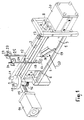
- crank mechanism In the device according to the invention according to FIG. 1, four shirring plates 1, 2, 3, 4 run in guide rails 5, 6, 7, 8 and are driven in opposite directions via a crank mechanism.
- the crank mechanism consists of a crank disk 9 with two crank pins 10, 11, which are connected to pins 12, 13 via only indicated crank rods.
- the pin 12 is rigidly connected to the shirring plates 1, 2, while the shirring plates 3, 4 are driven via the pin 13.
- the crank disk 9 is set in alternating rotation by a pneumatic cylinder 14 via a rack 15 and a gearwheel 16.
- Only one bending punch 17 and one cutting block 18 are shown in FIG. 1.
- the outer shirring plates 1, 2, which are provided with cutting and bending devices, are thicker than the other shirring plates.
- the gathered area is kept as short as possible, for which purpose the outer shirring plates 1, 2 are chamfered at the edges touching the hose, for example at 19.
- Another pneumatic cylinder 20 is used in the device according to FIG. 1 to actuate two closing irons for the clips, which are otherwise not shown in FIG. 1.
- the cutting and bending devices on the rafters 1, 2 are fed the wire 21, 22 from a supply roll, not shown, via a tube 24, 25, which swings around an axis 23. These tubes stabilize the wire in the area in front of the cutting device 18 so that it is not deformed by the bending moments that occur due to the cutting.
- the inner diameter of the tubes 24, 25 is chosen so large that the wires 21, 22 can be easily passed through.
- the cutting block 18 and the bending punch 17 include a fixed cutting edge and a bending die, which are arranged in a stationary manner on a strut fastened to the guide rails 5, 6, which is only indicated in FIG. 1.
- a more detailed description of the cutting and bending device and of a transport device for the clips (not shown in FIG. 1) is given later in connection with FIGS. 4 and 5.
- the filled hose to be processed is passed through the device in the direction of arrow 27.
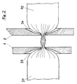
- FIG. 2 shows the gathering of the hose to form the ends of two successive tubular bag packs 31, 32, only the outer packer plates 1, 2 being shown.
- the gathering plates are chamfered at 33, 34, so that the gathering does not have to take an unnecessarily long distance, with much filling material to be displaced.
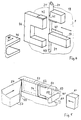
- Fig. 3 shows the same location of the device according to Fig. 1, but cut horizontally, in the closed state and with two further inner shirring plates 35, 36.
- the clips 37, 38 are already deformed so that the tubular bag packs 31, 32 are closed.
- a knife 39 driven by a pneumatic cylinder 20 (not shown) (FIG. 1), then cuts the gathered area 40.
- a counterholder can be arranged on the opposite side of the gathered area 40, preferably made of plastic, against which the knife 39 moves during the cutting process.
- FIG. 4 shows, in an enlarged representation compared to FIG. 1, the bending punch 17 and the cutting block 18 on the shirring plate 1, which can be moved back and forth in the direction of the double arrow.
- the cutting block 18 has a shoulder at 41, so that when moving to the left (opening of the shirring plates) the cutting block 18 moves the guide tube 24 of the wire 21 and the wire 21 itself to the left against the shear bar 42, so that the downward protrusion End 43 of the wire 21 is cut off.
- the cut wire end is pressed by the further movement of the shirring plate 1 to the left of the bending punch 17 into the bending die 44, so that a U-shaped clip results.
- the U-shaped clip is driven by a plunger 46 driven by a pneumatic cylinder, not shown, in the direction of arrow 45, through an opening 47 in the shirring plate 1 into a guide groove 51 (FIG. 5) in a behind the shirring plate 1 lying transport device encountered.
- the U-shaped clip 52 is pushed by a slider 53 into the position on the gathered hose 40 that is required to close the clip.
- the end of the slide 53 facing away from the clip 52 is perpendicular to the direction of movement of the Slider 53 a bolt 54 is provided which is driven in the direction of the arrow by a pneumatic cylinder, not shown.
- the latch 54 has a bevel 55 on which the left edge of the slide 53 slides when the latch 54 is moved in the direction of the arrow.
- the latch 54 is moved until it reaches the dotted position.
- the clip 52 has assumed the position required for closing.
- the dotted edge 56 of the slider 53 then no longer touches the bevel 55, but rather the side surface 57 of the bolt 54.
- the slider 53 and thus the clip 52 are fixed in the assumed position, so that a force emanating from a closing iron 61 is applied does not bring the clip 52 out of the assumed position.
- the bottom 58 of the U-shaped clip 52 is in contact with the gathered area 40 of the hose.
- the legs 59, 60 of the clip can thus be bent cleanly around the area 40.
Landscapes
- Engineering & Computer Science (AREA)
- Life Sciences & Earth Sciences (AREA)
- Mechanical Engineering (AREA)
- Wood Science & Technology (AREA)
- Zoology (AREA)
- Food Science & Technology (AREA)
- Containers And Plastic Fillers For Packaging (AREA)
- Package Closures (AREA)
Claims (10)
- Dispositif pour la fabrication d'emballages sous forme de sachets tubulaires remplis et fermés à partir d'un tuyeau flexible rempli, ce tuyeau flexible étant ramassé pour former à chaque fois les bouts de deux emballages sous forme de sachets successifs (31, 32) et la zone rammassée (40) du tuyeau étant fermée par deux agrafes (37, 38), celles-ci se trouvant à distance l'une par rapport à l'autre tout en formant une boucle, comportant deux groupes de tôles de ramasságe (1, 2, 5, 6, 35, 36), qui sont déplaçables à partir de deux côtés opposés vers la zone à ramasser du tuyeau, et étant pourvu de dispositifs (17, 18, 42, 44) pour découper et recourber des agrafes et pour transporter (51 - 56) les agrafes recourbées vers la zone ramassée du tuyeau, caractérisé en ce que des dispositifs (17, 18, 42, 44), chacun comprenant des parties stationnaires et et des parties mobiles pour découper et recourber le fil pourvu pour les agrafes, sont arrangés à l'extérieur des tôles de ramassage extérieures (1, 2), les parties mobiles (17, 18) étant montées sur les côtés extérieurs des tôles de ramassage extérieures (1, 2), que les tôles de ramassage extérieures (1, 2) ont une épaisseur plus forte que les autres tôles de ramassage (3, 4, 35, 36) et qu'un coulisseau (46) respectif ayant une direction de travail perpendiculaire par rapport aux tôles de ramassage extérieures (1, 2) est commandable et formé de sorte que les agrafes en U (52) soient poussées par les dispositifs de recourbement (17, 44) dans le dispositif de transport (51 - 56) à travers une orifice (47) respective dans les tôles de ramassage extérieures (1, 2).
- Dispositif suivant la revendication 1, caractérisé en ce que les tôles de ramassage extérieures (1, 2) sont guidées séparément.
- Dispositif suivant une des revendications 1 ou 2, caractérisé en ce que les tôles de ramassage extérieures (1, 2) présentent, concernant leur épaisseur, une forme oblique au niveau des arêtes qui entrent en contact avec le tuyeau.
- Dispositif suivant une des revendications mentionnées ci-dessus, caractérisé en ce que le dispositif de transport est composé d'une rainure de guidage (51) pour l'agrafe en U (52) et d'un curseur (53) qui est fixé lorsque la position requise pour le recourbement de l'agrafe en U (52) est atteinte.
- Dispositif suivant la revendication 4, caractérisé en ce que, pour la commande du curseur (53), un verrou (54) ayant une direction de travail perpendiculaire par rapport aux tôles de ramassage extérieures (1, 2) possède une surface oblique (55), qui est en contact avec et actionne sue le curseur (53), tel que la surface oblique (55) effectue un mouvement du curseur (53) vers la position requise pour le recourbement et qu'une surface latérale (57) du verrou (54) adjacente à la surface oblique (55) effectue la fixation du curseur (53).
- Dispositif suivant une des revendications mentionnées ci-dessus, caractérisé en ce que le profilé de fermeture (61) pourvu pour fermer l'agrafe est arrangé sur le côté opposé du dispositif de transport (51, 53, 54) et est formé de sorte que les branches (59, 60) de l'agrafe en U (52) soient juxtaposées en état recourbé.
- Dispositif suivant une des revendications mentionnées ci-dessus, caractérisé en ce que les tôles de ramassage (1, 2, 35, 36; 3, 4) peuvent être commandées par groupes à mouvements contraires moyennant une commande à manivelle (9, 10, 11).
- Dispositif suivant une des revendications mentionnées ci-dessus, caractérisé en ce que le fil (21, 22) peut être amené au dispositif de découpage (18) à partir d'une bobine d'alimentation respective par l'intermédiaire d'un tube (24, 25), ce tube (24, 25) étant suspendu comme une pendule à un point de rotation (23) qui est situé près de l'orifice d'entrée du tube (24, 25) pour le fil (21, 22), et que l'orifice de sortie du tube (24, 25) suit essentiellement le mouvement de la tôle de ramassage (1, 2).
- Dispositif suivant une des revendications mentionnées ci-dessus, caractérisé en ce que le dispositif est construit sous forme d'ensemble compact qui peut être monté comme dispositif supplémentaire sur les installations de mise en sachets tubulaires.
- Dispositif suivant une des revendications mentionnées ci-dessus, caractérisé en ce qu'un couteau (39) pour la séparation des sachets tubulaires (31, 32) est arrangé en face des tôles de ramassage (1, 2) qui portent les dispositifs (17, 18) de découpage et de recourbement.
Applications Claiming Priority (2)
| Application Number | Priority Date | Filing Date | Title |
|---|---|---|---|
| DE4418894 | 1994-05-31 | ||
| DE4418894 | 1994-05-31 |
Publications (2)
| Publication Number | Publication Date |
|---|---|
| EP0685397A1 EP0685397A1 (fr) | 1995-12-06 |
| EP0685397B1 true EP0685397B1 (fr) | 1997-08-06 |
Family
ID=6519363
Family Applications (1)
| Application Number | Title | Priority Date | Filing Date |
|---|---|---|---|
| EP95108381A Expired - Lifetime EP0685397B1 (fr) | 1994-05-31 | 1995-05-29 | Dispositif pour la fabrication de sachets d'emballage tubulaires remplis et fermés |
Country Status (2)
| Country | Link |
|---|---|
| EP (1) | EP0685397B1 (fr) |
| DE (2) | DE59500464D1 (fr) |
Cited By (3)
| Publication number | Priority date | Publication date | Assignee | Title |
|---|---|---|---|---|
| DE19754199C1 (de) * | 1997-12-06 | 1999-06-24 | Knieriem Guenther Dipl Ing Fh | Vorrichtung zum Herstellen von gefüllten, verschlossenen Schlauchbeutelpackungen |
| DE102004022716B4 (de) * | 2003-05-17 | 2014-01-23 | Waltraud Knieriem | Vorrichtung zum Herstellen von gefüllten, verschlossenen Schlauchbeutelpackungen |
| US9009924B2 (en) | 2010-12-24 | 2015-04-21 | Viktor Schnyder | Clip-closure |
Families Citing this family (3)
| Publication number | Priority date | Publication date | Assignee | Title |
|---|---|---|---|---|
| DE19960084A1 (de) * | 1999-12-13 | 2001-06-21 | Kraemer & Grebe Kg | Verpackungsmaschine |
| DE10131807C1 (de) | 2001-06-30 | 2002-11-07 | Poly Clip System Gmbh & Co Kg | Portionierungsvorrichtung |
| DE102007012777B4 (de) | 2007-03-16 | 2010-06-24 | Poly-Clip System Gmbh & Co Kg | Verfahren und Vorrichtung zum gesteuerten Verschließen wenigstens eines Clips um einen füllgutfreien Zopfabschnitt zwischen zwei mit einer Hülle umschlossenen Füllgutabschnitten |
Family Cites Families (10)
| Publication number | Priority date | Publication date | Assignee | Title |
|---|---|---|---|---|
| DE826843C (de) | 1946-03-04 | 1952-01-07 | Hercules Fasteners Inc | Ringverschluss zum Verschliessen der Enden von Huellen |
| US3079067A (en) * | 1953-08-06 | 1963-02-26 | Kartridg Pak Co | Clips and method for sealing containers therewith |
| US2831302A (en) * | 1954-10-06 | 1958-04-22 | Mayer & Co Inc O | Packaging machine |
| US3149447A (en) | 1961-12-08 | 1964-09-22 | Mayer & Co Inc O | Tube feeding mechanism for packaging machine |
| US3324621A (en) * | 1963-06-10 | 1967-06-13 | Mayer & Co Inc O | Packaging machine |
| JPS4841665U (fr) * | 1971-09-17 | 1973-05-28 | ||
| US3795083A (en) | 1972-06-06 | 1974-03-05 | Kartridg Pak Co | Wraparound closure clip applying mechanism |
| US3992854A (en) | 1976-02-18 | 1976-11-23 | The Kartridg Pak Co. | Method and apparatus for making dual compartment package |
| US4211051A (en) | 1978-01-19 | 1980-07-08 | The Kartridg Pak Co. | Cut-off device for chub machines |
| DE3333875A1 (de) | 1983-09-20 | 1985-03-28 | Herbert Dipl.-Ing. 6240 Königstein Niedecker | Vorrichtung zum verschliessen von schlauchartigen verpackungshuellen mit u-foermigen verschlussklammern |
-
1995
- 1995-05-29 DE DE59500464T patent/DE59500464D1/de not_active Expired - Fee Related
- 1995-05-29 DE DE19519591A patent/DE19519591C2/de not_active Expired - Fee Related
- 1995-05-29 EP EP95108381A patent/EP0685397B1/fr not_active Expired - Lifetime
Cited By (3)
| Publication number | Priority date | Publication date | Assignee | Title |
|---|---|---|---|---|
| DE19754199C1 (de) * | 1997-12-06 | 1999-06-24 | Knieriem Guenther Dipl Ing Fh | Vorrichtung zum Herstellen von gefüllten, verschlossenen Schlauchbeutelpackungen |
| DE102004022716B4 (de) * | 2003-05-17 | 2014-01-23 | Waltraud Knieriem | Vorrichtung zum Herstellen von gefüllten, verschlossenen Schlauchbeutelpackungen |
| US9009924B2 (en) | 2010-12-24 | 2015-04-21 | Viktor Schnyder | Clip-closure |
Also Published As
| Publication number | Publication date |
|---|---|
| DE19519591C2 (de) | 2003-11-13 |
| DE59500464D1 (de) | 1997-09-11 |
| DE19519591A1 (de) | 1995-12-07 |
| EP0685397A1 (fr) | 1995-12-06 |
Similar Documents
| Publication | Publication Date | Title |
|---|---|---|
| DE69900236T2 (de) | Verfahren und Maschine zur Herstellung von Beuteln mit einem transversalen Reissverschluss | |
| DE3886769T2 (de) | Verpackungsvorrichtung für die Verwendung von schlauchförmigem Hüllenmaterial. | |
| DE2200419C3 (de) | Vorrichtung zur intermittierenden Zufuhr eines Abschnitts einer Folienbahn aus einer Vorratsrolle zum Verschließen eines Behälters | |
| DE2628322C2 (fr) | ||
| DE7635390U1 (de) | Bahnabstreifvorrichtung für Beutelherstellungsmaschinen | |
| DE102005029227B4 (de) | Clipmaschine | |
| EP0685397B1 (fr) | Dispositif pour la fabrication de sachets d'emballage tubulaires remplis et fermés | |
| DE3128043A1 (de) | Vorrichtung zum verpacken von pulver, granulaten, stueckigen, pastoesen und fluessigen verpackungsguetern mittels einer schlauchfoermigen folie | |
| DE69507012T2 (de) | Vorrichtung zum verpacken von geflügel und anderen gegenständen | |
| EP1969946B1 (fr) | Avancement à clip réglable | |
| DE2420642A1 (de) | Verfahren und vorrichtung zum kontinuierlichen automatischen herstellen und befuellen von kunststoffbeuteln mit einem inhalt von vorbestimmtem gleichem gewicht | |
| DE2241544A1 (de) | Verschluss und vorrichtung zum verschliessen von flexiblen behaeltnissen, beispielsweise von plastikhuellen | |
| DE2730121A1 (de) | Verfahren und vorrichtung zum abteilen von packungen von einem gefuellten schlauch | |
| DE1411489A1 (de) | Vorrichtung zum Herstellen von Verpackungen | |
| EP0527743A1 (fr) | Procede et machine de ficelage de paquets ou de piles avec un ruban en matiere plastique soudable | |
| DE102004022716B4 (de) | Vorrichtung zum Herstellen von gefüllten, verschlossenen Schlauchbeutelpackungen | |
| DE102014214019A1 (de) | Verfahren zur Herstellung von Umreifungsgebinden und Applikationseinheit einer Umreifungsvorrichtung zur Herstellung von Umreifungsgebinden | |
| DE3633428A1 (de) | Vorrichtung zum durchtrennen eines faserbandes bei einer spinnereivorbereitungsmaschine, insbesondere einer strecke | |
| DE2640050A1 (de) | Bandumwindungsvorrichtung an einer verpackungsmaschine | |
| DE2711430A1 (de) | Verschluss- und abschneidevorrichtung fuer zusammengeraffte verpackungsschlaeuche, wie wursthuellen, beutel u.dgl. | |
| DE4234467C2 (de) | Vorrichtung zum Befestigen einer U-förmigen Metallklammer um ein gerafftes Hüllenmaterial | |
| DE60015620T2 (de) | Vorrichtung zum Herstellen von Beuteln, Säcken und dergleichen | |
| DE3434715C2 (fr) | ||
| DE1078042B (de) | Verfahren zum Verpacken von stueckigen Guetern und Vorrichtung zur Durchfuehrung dieses Verfahrens | |
| DE3024517A1 (de) | Vorrichtung zum verschweissen von folienpackungen |
Legal Events
| Date | Code | Title | Description |
|---|---|---|---|
| PUAI | Public reference made under article 153(3) epc to a published international application that has entered the european phase |
Free format text: ORIGINAL CODE: 0009012 |
|
| 17P | Request for examination filed |
Effective date: 19950623 |
|
| AK | Designated contracting states |
Kind code of ref document: A1 Designated state(s): CH DE IT LI NL |
|
| 17Q | First examination report despatched |
Effective date: 19960418 |
|
| GRAG | Despatch of communication of intention to grant |
Free format text: ORIGINAL CODE: EPIDOS AGRA |
|
| GRAH | Despatch of communication of intention to grant a patent |
Free format text: ORIGINAL CODE: EPIDOS IGRA |
|
| GRAH | Despatch of communication of intention to grant a patent |
Free format text: ORIGINAL CODE: EPIDOS IGRA |
|
| GRAA | (expected) grant |
Free format text: ORIGINAL CODE: 0009210 |
|
| AK | Designated contracting states |
Kind code of ref document: B1 Designated state(s): CH DE IT LI NL |
|
| PG25 | Lapsed in a contracting state [announced via postgrant information from national office to epo] |
Ref country code: NL Free format text: LAPSE BECAUSE OF FAILURE TO SUBMIT A TRANSLATION OF THE DESCRIPTION OR TO PAY THE FEE WITHIN THE PRESCRIBED TIME-LIMIT Effective date: 19970806 |
|
| REG | Reference to a national code |
Ref country code: CH Ref legal event code: EP |
|
| REF | Corresponds to: |
Ref document number: 59500464 Country of ref document: DE Date of ref document: 19970911 |
|
| ITF | It: translation for a ep patent filed | ||
| NLV1 | Nl: lapsed or annulled due to failure to fulfill the requirements of art. 29p and 29m of the patents act | ||
| PLBE | No opposition filed within time limit |
Free format text: ORIGINAL CODE: 0009261 |
|
| STAA | Information on the status of an ep patent application or granted ep patent |
Free format text: STATUS: NO OPPOSITION FILED WITHIN TIME LIMIT |
|
| 26N | No opposition filed | ||
| PGFP | Annual fee paid to national office [announced via postgrant information from national office to epo] |
Ref country code: DE Payment date: 20080520 Year of fee payment: 14 Ref country code: CH Payment date: 20080526 Year of fee payment: 14 |
|
| PGFP | Annual fee paid to national office [announced via postgrant information from national office to epo] |
Ref country code: IT Payment date: 20080527 Year of fee payment: 14 |
|
| REG | Reference to a national code |
Ref country code: CH Ref legal event code: PL |
|
| PG25 | Lapsed in a contracting state [announced via postgrant information from national office to epo] |
Ref country code: LI Free format text: LAPSE BECAUSE OF NON-PAYMENT OF DUE FEES Effective date: 20090531 Ref country code: CH Free format text: LAPSE BECAUSE OF NON-PAYMENT OF DUE FEES Effective date: 20090531 |
|
| PG25 | Lapsed in a contracting state [announced via postgrant information from national office to epo] |
Ref country code: DE Free format text: LAPSE BECAUSE OF NON-PAYMENT OF DUE FEES Effective date: 20091201 |
|
| PG25 | Lapsed in a contracting state [announced via postgrant information from national office to epo] |
Ref country code: IT Free format text: LAPSE BECAUSE OF NON-PAYMENT OF DUE FEES Effective date: 20090529 |