EP0685397B1 - Apparatus for making filled, closed bag-like tubular packages - Google Patents
Apparatus for making filled, closed bag-like tubular packages Download PDFInfo
- Publication number
- EP0685397B1 EP0685397B1 EP95108381A EP95108381A EP0685397B1 EP 0685397 B1 EP0685397 B1 EP 0685397B1 EP 95108381 A EP95108381 A EP 95108381A EP 95108381 A EP95108381 A EP 95108381A EP 0685397 B1 EP0685397 B1 EP 0685397B1
- Authority
- EP
- European Patent Office
- Prior art keywords
- hose
- bending
- clips
- gathering plates
- arrangement according
- Prior art date
- Legal status (The legal status is an assumption and is not a legal conclusion. Google has not performed a legal analysis and makes no representation as to the accuracy of the status listed.)
- Expired - Lifetime
Links
Images

Classifications
-
- B—PERFORMING OPERATIONS; TRANSPORTING
- B65—CONVEYING; PACKING; STORING; HANDLING THIN OR FILAMENTARY MATERIAL
- B65B—MACHINES, APPARATUS OR DEVICES FOR, OR METHODS OF, PACKAGING ARTICLES OR MATERIALS; UNPACKING
- B65B51/00—Devices for, or methods of, sealing or securing package folds or closures; Devices for gathering or twisting wrappers, or necks of bags
- B65B51/04—Applying separate sealing or securing members, e.g. clips
-
- A—HUMAN NECESSITIES
- A22—BUTCHERING; MEAT TREATMENT; PROCESSING POULTRY OR FISH
- A22C—PROCESSING MEAT, POULTRY, OR FISH
- A22C11/00—Sausage making ; Apparatus for handling or conveying sausage products during manufacture
- A22C11/12—Apparatus for tying sausage skins ; Clipping sausage skins
- A22C11/125—Apparatus for tying sausage skins ; Clipping sausage skins by clipping; Removal of clips
Definitions
- the invention relates to a device for producing filled, closed tubular pouch packs from a filled tube, the filled tube being gathered to form the ends of two successive tubular pouch packs and the gathered area of the tube being closed with two spaced-apart clips, two groups of Saddle plates can be shifted from two opposite sides against the area of the hose to be gathered and devices for cutting and bending the clips and for transporting the bent clips to the gathered area of the hose are provided.
- Aluminum closures - so-called clips - are mainly used to seal tubular bag packs or sausages. These are not manufactured by the consumer, but separately. The wire is cut and shaped into U-shaped clip closures. These finished clip fasteners are then connected to so-called clip bars for better handling by means of adhesive strips on the foot and are thus sold.
- the clip magazines of the double locking devices are filled with these clip bars.
- the clips are separated and the gathered film is wrapped in a loop.
- These clip magazines have a limited volume of approximately 400, i.e. at a filling rate of 20 pieces per minute, the magazine is empty after 20 minutes of operation and must be refilled. This always leads to short interruptions in production (DE 826843, EP 0 135 238).
- the closing device is firmly connected to the entire system via the mechanics and is part of this system.
- the cutting device for separating the packs ie for separating the film between the closures, is connected downstream of the sealing device, but is also mechanically connected to it, ie the upstream stationary seal forming station, the downstream external cutting station for separating the packs and before All of the closing stations, which have to be moved back and forth, are permanently connected to the tubular bag filling system via the mechanics and the drives. This requires a high level of technical effort. It is practically not feasible to use this closure manufacturing, closing and separating device in a tubular bag filling system of another make (US Pat. Nos. 2,831,302, 3,149,447, 3,324,621, 3,795,083, 3,992,854, DE 28 48 706).
- a device according to the preamble of the main claim is described in US 3,079,067.
- Devices for cutting and bending the clips from band-shaped raw material are provided above, between and below the shirring plates.
- Two pneumatic cylinders are used to drive this device.
- the invention has for its object to provide a device for producing tubular bag packs, in which the clips are formed directly from the wire provided, so that production, transport and frequent reloading of the clip bars can be omitted, and in which Cutting, bending and transporting clips within the closing device requires as little effort as possible in terms of drive and control means.
- devices for cutting and bending the wire provided for the clips which consist of fixed parts and movable parts, are arranged outside the outer shirred plates, the movable parts being mounted on the outer sides of the outer shirred plates, that the outer shirring plates have a greater thickness than the other shirring plates and that in each case a tappet can be driven with a working direction perpendicular to the outer shirring plates and is designed that the U-shaped clips are pushed into the transport device by the devices for bending through an opening in the outer shirring plates.
- This device is characterized by a compact design and enables easy feeding of the U-shaped curved clips to the gathered area. This makes the device lighter and cheaper than known devices. It also ensures that the outer shirring plates are not deformed by the force required for cutting and bending.
- the outer shirring plates are beveled with respect to their thickness at the edges coming into contact with the hose.
- the transport device consists of a guide groove for the U-shaped clip and a slide which is fixed when the U-shaped clip is reached for the position required for bending. This ensures proper closing by the subsequent bending process with the help of a closing iron acting against the slide.
- a secure fixation is achieved in an advantageous embodiment of the development in that for driving the slide, a bolt with a working direction perpendicular to the outer shirring plates has an inclined surface, which is operatively connected to the slide such that a movement of the Slider in the direction of the position required for bending and by an adjacent to the inclined surface The slide is fixed on the side surface of the bolt.
- a closing iron provided for closing the clip is arranged on the side opposite the transport device and is shaped such that the legs of the U-shaped clip lie next to one another in the bent state.
- Another advantageous embodiment of the device according to the invention consists in the fact that the packer plates can be driven in groups in opposite directions with the aid of a crank mechanism. This ensures that the filled hose fed is gathered in the middle and that a sufficient force acts on the outer shirring plates for cutting and bending the wire.
- a chain drive is also possible within the scope of the invention.
- the wire that is fed in must largely follow the movement of the outer shirring plates, but the piece of wire that is fed in should not be deformed.
- the device In order to use a device according to the invention as an additional device on any tubular bag filling systems, another development provides that the device is designed as a self-contained assembly that can be mounted as an additional device on tubular bag filling systems.
- a knife for separating the tubular bag packs is arranged in relation to the packer plates carrying the devices for cutting and bending.
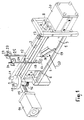
- crank mechanism In the device according to the invention according to FIG. 1, four shirring plates 1, 2, 3, 4 run in guide rails 5, 6, 7, 8 and are driven in opposite directions via a crank mechanism.
- the crank mechanism consists of a crank disk 9 with two crank pins 10, 11, which are connected to pins 12, 13 via only indicated crank rods.
- the pin 12 is rigidly connected to the shirring plates 1, 2, while the shirring plates 3, 4 are driven via the pin 13.
- the crank disk 9 is set in alternating rotation by a pneumatic cylinder 14 via a rack 15 and a gearwheel 16.
- Only one bending punch 17 and one cutting block 18 are shown in FIG. 1.
- the outer shirring plates 1, 2, which are provided with cutting and bending devices, are thicker than the other shirring plates.
- the gathered area is kept as short as possible, for which purpose the outer shirring plates 1, 2 are chamfered at the edges touching the hose, for example at 19.
- Another pneumatic cylinder 20 is used in the device according to FIG. 1 to actuate two closing irons for the clips, which are otherwise not shown in FIG. 1.
- the cutting and bending devices on the rafters 1, 2 are fed the wire 21, 22 from a supply roll, not shown, via a tube 24, 25, which swings around an axis 23. These tubes stabilize the wire in the area in front of the cutting device 18 so that it is not deformed by the bending moments that occur due to the cutting.
- the inner diameter of the tubes 24, 25 is chosen so large that the wires 21, 22 can be easily passed through.
- the cutting block 18 and the bending punch 17 include a fixed cutting edge and a bending die, which are arranged in a stationary manner on a strut fastened to the guide rails 5, 6, which is only indicated in FIG. 1.
- a more detailed description of the cutting and bending device and of a transport device for the clips (not shown in FIG. 1) is given later in connection with FIGS. 4 and 5.
- the filled hose to be processed is passed through the device in the direction of arrow 27.
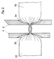
- FIG. 2 shows the gathering of the hose to form the ends of two successive tubular bag packs 31, 32, only the outer packer plates 1, 2 being shown.
- the gathering plates are chamfered at 33, 34, so that the gathering does not have to take an unnecessarily long distance, with much filling material to be displaced.
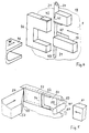
- Fig. 3 shows the same location of the device according to Fig. 1, but cut horizontally, in the closed state and with two further inner shirring plates 35, 36.
- the clips 37, 38 are already deformed so that the tubular bag packs 31, 32 are closed.
- a knife 39 driven by a pneumatic cylinder 20 (not shown) (FIG. 1), then cuts the gathered area 40.
- a counterholder can be arranged on the opposite side of the gathered area 40, preferably made of plastic, against which the knife 39 moves during the cutting process.
- FIG. 4 shows, in an enlarged representation compared to FIG. 1, the bending punch 17 and the cutting block 18 on the shirring plate 1, which can be moved back and forth in the direction of the double arrow.
- the cutting block 18 has a shoulder at 41, so that when moving to the left (opening of the shirring plates) the cutting block 18 moves the guide tube 24 of the wire 21 and the wire 21 itself to the left against the shear bar 42, so that the downward protrusion End 43 of the wire 21 is cut off.
- the cut wire end is pressed by the further movement of the shirring plate 1 to the left of the bending punch 17 into the bending die 44, so that a U-shaped clip results.
- the U-shaped clip is driven by a plunger 46 driven by a pneumatic cylinder, not shown, in the direction of arrow 45, through an opening 47 in the shirring plate 1 into a guide groove 51 (FIG. 5) in a behind the shirring plate 1 lying transport device encountered.
- the U-shaped clip 52 is pushed by a slider 53 into the position on the gathered hose 40 that is required to close the clip.
- the end of the slide 53 facing away from the clip 52 is perpendicular to the direction of movement of the Slider 53 a bolt 54 is provided which is driven in the direction of the arrow by a pneumatic cylinder, not shown.
- the latch 54 has a bevel 55 on which the left edge of the slide 53 slides when the latch 54 is moved in the direction of the arrow.
- the latch 54 is moved until it reaches the dotted position.
- the clip 52 has assumed the position required for closing.
- the dotted edge 56 of the slider 53 then no longer touches the bevel 55, but rather the side surface 57 of the bolt 54.
- the slider 53 and thus the clip 52 are fixed in the assumed position, so that a force emanating from a closing iron 61 is applied does not bring the clip 52 out of the assumed position.
- the bottom 58 of the U-shaped clip 52 is in contact with the gathered area 40 of the hose.
- the legs 59, 60 of the clip can thus be bent cleanly around the area 40.
Landscapes
- Engineering & Computer Science (AREA)
- Life Sciences & Earth Sciences (AREA)
- Wood Science & Technology (AREA)
- Zoology (AREA)
- Food Science & Technology (AREA)
- Mechanical Engineering (AREA)
- Containers And Plastic Fillers For Packaging (AREA)
- Package Closures (AREA)
Description
Die Erfindung betrifft eine Vorrichtung zum Herstellen von gefüllten, verschlossenen Schlauchbeutelpackungen aus einem gefüllten Schlauch, wobei der gefüllte Schlauch zur Bildung der Enden jeweils zweier aufeinanderfolgender Schlauchbeutelpackungen gerafft wird und der geraffte Bereich des Schlauchs mit zwei voneinander beabstandeten Clips umschlingend verschlossen wird, wobei zwei Gruppen von Rafferblechen von zwei gegenüberliegenden Seiten gegen den zu raffenden Bereich des Schlauchs verschiebbar sind und wobei Vorrichtungen zum Schneiden und Biegen der Clips und zum Transport der gebogenen Clips zum gerafften Bereich des Schlauchs vorgesehen sind.The invention relates to a device for producing filled, closed tubular pouch packs from a filled tube, the filled tube being gathered to form the ends of two successive tubular pouch packs and the gathered area of the tube being closed with two spaced-apart clips, two groups of Saddle plates can be shifted from two opposite sides against the area of the hose to be gathered and devices for cutting and bending the clips and for transporting the bent clips to the gathered area of the hose are provided.
Zum Verschließen von Schlauchbeutelpackungen oder Würsten werden überwiegend Aluminium-Verschlüsse - sogenannte Clips - eingesetzt. Diese werden nicht beim Verbraucher, sondern separat hergestellt. Dabei wird der Draht geschnitten und zu U-förmigen Clip-Verschlüssen geformt. Diese fertigen Clip-Verschlüsse werden dann zur besseren Handhabung mittels Klebestreifen am Fuß zu sogenannten Clip-Riegeln verbunden und gelangen so in den Handel.Aluminum closures - so-called clips - are mainly used to seal tubular bag packs or sausages. These are not manufactured by the consumer, but separately. The wire is cut and shaped into U-shaped clip closures. These finished clip fasteners are then connected to so-called clip bars for better handling by means of adhesive strips on the foot and are thus sold.
Vor der Verwendung der Clips werden die Clip-Magazine der Doppelverschließvorrichtungen mit diesen Clip-Riegeln aufgefüllt. Beim Verarbeiten werden die Clips vereinzelt und die geraffte Folie umschlingend verschlossen. Diese Clip-Magazine haben ein begrenztes Volumen von etwa 400 Stück, d.h. bei einer Abfülleistung von 20 Stück pro Minute ist das Magazin nach 20 Minuten Betriebszeit leer und muß neu befüllt werden. Dieses führt stets zu kurzen Produktionsunterbrechungen (DE 826843, EP 0 135 238).Before the clips are used, the clip magazines of the double locking devices are filled with these clip bars. During processing, the clips are separated and the gathered film is wrapped in a loop. These clip magazines have a limited volume of approximately 400, i.e. at a filling rate of 20 pieces per minute, the magazine is empty after 20 minutes of operation and must be refilled. This always leads to short interruptions in production (DE 826843, EP 0 135 238).
Eine Verbesserung wurde erzielt, als man dazu überging, die Herstellvorrichtung für die U-förmigen Clips einer kombinierten Form-, Füll-, Verschließ- und Trennvorrichtung für Schlauchbeutel vorzulagern oder diese miteinander zu verbinden. In einer externen Vorrichtung werden dabei die beiden Aluminiumdrähte von den beiden Drahtrollenmagazinen abgezogen, in abgelängte Stücke geschnitten und zu je zwei U-förmigen Clip-Verschlüssen geformt. Die vorgefertigten Clip-Verschlüsse werden dann zum Verschließen der Packungen in die Verschließvorrichtung, die in der Abfüllanlage integriert ist, eingeführt. Bei diesem Verfahren wird der Folienschlauch kontinuierlich transportiert. Die Verschließvorrichtung muß während des Raff- und Verschließvorganges mit der Folie mitgeführt werden, d.h., während die Verschlüsse stationär extern geschnitten werden, führt die Verschließvorrichtung eine ständige Hin- und Herbewegung aus.An improvement was achieved when it started to pre-store the connecting device for the U-shaped clips of a combined form, fill, seal and separate device for tubular bags or to connect them to one another. In an external device, the two aluminum wires are pulled off the two wire reel magazines, cut into cut pieces and formed into two U-shaped clip closures. The prefabricated clip closures are then inserted into the closure device, which is integrated in the filling system, to close the packs. With this process, the film tube is transported continuously. The sealing device must be carried along with the film during the gathering and sealing process, i.e., while the seals are being cut externally in a stationary manner, the sealing device carries out a constant reciprocating movement.
Die Verschließvorrichtung ist mit der Gesamtanlage über die Mechanik fest verbunden und ist ein Bestandteil dieser Anlage. Die Schneidvorrichtung zum Vereinzeln der Packungen, d.h. zum Trennen der Folie zwischen den Verschlüssen, ist der Verschließvorrichtung nachgeschaltet, ist aber ebenfalls mit dieser mechanisch verbunden, d.h. die vorgeschaltete stationäre Verschluß-Formstation, die nachgeschaltete externe Schneidestation zum Vereinzeln der Packungen und vor allem die ständig hin und her zu bewegende Verschließstation sind mit der Schlauchbeutel-Abfüllanlage über die Mechanik und die Antriebe fest verbunden. Dieses erfordert einen hohen technischen Aufwand. Ein Einsatz dieser Verschlußherstell-, Verschließ- und Trennvorrichtung in einer Schlauchbeutel-Abfüllanlage anderen Fabrikats ist praktisch nicht durchführbar (US-PS 2,831,302, 3,149,447, 3,324,621, 3,795,083, 3,992,854, DE 28 48 706).The closing device is firmly connected to the entire system via the mechanics and is part of this system. The cutting device for separating the packs, ie for separating the film between the closures, is connected downstream of the sealing device, but is also mechanically connected to it, ie the upstream stationary seal forming station, the downstream external cutting station for separating the packs and before All of the closing stations, which have to be moved back and forth, are permanently connected to the tubular bag filling system via the mechanics and the drives. This requires a high level of technical effort. It is practically not feasible to use this closure manufacturing, closing and separating device in a tubular bag filling system of another make (US Pat. Nos. 2,831,302, 3,149,447, 3,324,621, 3,795,083, 3,992,854, DE 28 48 706).
Eine Vorrichtung gemäß dem Oberbegriff des Hauptanspruchs ist in US 3,079,067 beschrieben. Dabei sind Vorrichtungen zum Schneiden und Biegen der Clips aus bandförmigem Rohmaterial oberhalb, zwischen und unterhalb der Rafferbleche vorgesehen. Zum Antrieb dieser Vorrichtung dienen zwei Pneumatikzylinder.A device according to the preamble of the main claim is described in US 3,079,067. Devices for cutting and bending the clips from band-shaped raw material are provided above, between and below the shirring plates. Two pneumatic cylinders are used to drive this device.
Der Erfindung liegt die Aufgabe zugrunde, eine Vorrichtung zum Herstellen von Schlauchbeutelpackungen anzugeben, bei welcher die Clips unmittelbar aus dem dafür vorgesehenen Draht geformt werden, so daß eine Herstellung, ein Transport sowie ein häufiges Nachladen der Clip-Riegel entfallen können, und bei welcher zum Schneiden, Biegen und Transportieren von Clips innerhalb der Verschließvorrichtung ein möglichst geringer Aufwand an Antriebs- und Steuerungsmitteln erforderlich ist.The invention has for its object to provide a device for producing tubular bag packs, in which the clips are formed directly from the wire provided, so that production, transport and frequent reloading of the clip bars can be omitted, and in which Cutting, bending and transporting clips within the closing device requires as little effort as possible in terms of drive and control means.
Diese Aufgabe wird bei der erfindungsgemäßen Vorrichtung dadurch gelöst, daß jeweils aus feststehenden und aus beweglichen Teilen bestehende Vorrichtungen zum Schneiden und Biegen des für die Clips vorgesehenen Drahts außerhalb der äußeren Rafferbleche angeordnet sind, wobei die beweglichen Teile auf den Außenseiten der äußeren Rafferbleche montiert sind, daß die äußeren Rafferbleche eine größere Dicke als die anderen Rafferbleche aufweisen und daß jeweils ein Stößel mit einer Arbeitsrichtung senkrecht zu den äußeren Rafferblechen derart antreibbar und ausgebildet ist, daß die U-förmigen Clips von den Vorrichtungen zum Biegen durch je eine Öffnung in den äußeren Rafferblechen in die Transportvorrichtung gestoßen werden.This object is achieved in the device according to the invention in that devices for cutting and bending the wire provided for the clips, which consist of fixed parts and movable parts, are arranged outside the outer shirred plates, the movable parts being mounted on the outer sides of the outer shirred plates, that the outer shirring plates have a greater thickness than the other shirring plates and that in each case a tappet can be driven with a working direction perpendicular to the outer shirring plates and is designed that the U-shaped clips are pushed into the transport device by the devices for bending through an opening in the outer shirring plates.
Diese Vorrichtung zeichnet sich durch eine kompakte Bauform aus und ermöglicht eine einfache Zuführung der U-förmig gebogenen Clips zum gerafften Bereich. Damit ist die Vorrichtung auch leichter und preiswerter als bekannte Vorrichtungen. Ferner ist sichergestellt, daß die äußeren Rafferbleche durch die zum Schneiden und Biegen erforderliche Kraft nicht verformt werden.This device is characterized by a compact design and enables easy feeding of the U-shaped curved clips to the gathered area. This makes the device lighter and cheaper than known devices. It also ensures that the outer shirring plates are not deformed by the force required for cutting and bending.
Damit trotzdem möglichst wenig Füllmasse durch die Raffung verdrängt wird, ist bei einer Weiterbildung der erfindungsgemäßen Vorrichtung vorgesehen, daß die äußeren Rafferbleche an den mit dem Schlauch in Berührung kommenden Kanten bezüglich ihrer Dicke angeschrägt sind.So that as little filling material as possible is displaced by the gathering, it is provided in a development of the device according to the invention that the outer shirring plates are beveled with respect to their thickness at the edges coming into contact with the hose.
Bei der erfindungsgemäßen Vorrichtung ist vorzugsweise vorgesehen, daß die Transportvorrichtung aus einer Führungsnut für den U-förmigen Clip und einem Schieber besteht, der beim Erreichen der zum Biegen erforderlichen Position des U-förmigen Clips fixiert wird. Dadurch wird ein einwandfreies Verschließen durch den anschließenden Biegevorgang mit Hilfe eines gegen den Schieber wirkenden Schließeisens gewährleistet.In the device according to the invention it is preferably provided that the transport device consists of a guide groove for the U-shaped clip and a slide which is fixed when the U-shaped clip is reached for the position required for bending. This ensures proper closing by the subsequent bending process with the help of a closing iron acting against the slide.
Eine sichere Fixierung wird bei einer vorteilhaften Ausgestaltung der Weiterbildung dadurch erreicht, daß zum Antrieb des Schiebers ein Riegel mit einer Arbeitsrichtung senkrecht zu den äußeren Rafferblechen eine schräge Fläche aufweist, die mit dem Schieber derart in Wirkverbindung steht, daß durch die schräge Fläche eine Bewegung des Schiebers in Richtung auf die zum Biegen erforderliche Position und durch eine an die schräge Fläche angrenzende Seitenfläche des Riegels eine Fixierung des Schiebers erfolgt.A secure fixation is achieved in an advantageous embodiment of the development in that for driving the slide, a bolt with a working direction perpendicular to the outer shirring plates has an inclined surface, which is operatively connected to the slide such that a movement of the Slider in the direction of the position required for bending and by an adjacent to the inclined surface The slide is fixed on the side surface of the bolt.
An die Abdichtung der folienumschlingenden Verschlüsse werden insbesondere bei reaktiven Füllgütern, wie Dichtstoffen usw. hohe Ansprüche gestellt. Im direkten Zusammenhang hiermit steht die Lagerstabilität der Packungen. Des weiteren kann es durch die Erwärmung der Packungen, durch Preßdruck bei der Lagerung oder beim Verarbeiten zu Überdruck in der Packung kommen, der ein Abrutschen oder Aufbiegen des Verschlusses und damit ein Auslaufen des Füllguts zur Folge hat. Es wäre daher wichtig, daß der Verschluß möglichst fest auf der Folie sitzt und der Öffnungswiderstand des Verschlusses möglichst hoch ist, um ein Aufbiegen des Verschlusses bei erhöhtem Innendruck zu verhindern.High demands are placed on the sealing of the film-wrapping closures, particularly in the case of reactive filling materials, such as sealants, etc. The storage stability of the packs is directly related to this. Furthermore, heating of the packs, pressing pressure during storage or processing can result in overpressure in the pack, which results in the closure slipping or bending open and thus in a leakage of the filling material. It would therefore be important that the closure sits as tightly as possible on the film and that the opening resistance of the closure is as high as possible in order to prevent the closure from bending open under increased internal pressure.
Dieses wird bei einer Weiterbildung dadurch erzielt, daß ein zum Verschließen des Clips vorgesehenes Schließeisen auf der der Transportvorrichtung entgegengesetzten Seite angeordnet und derart geformt ist, daß die Schenkel des U-förmigen Clips im gebogenen Zustand nebeneinanderliegen.In a further development, this is achieved in that a closing iron provided for closing the clip is arranged on the side opposite the transport device and is shaped such that the legs of the U-shaped clip lie next to one another in the bent state.
Eine andere vorteilhafte Ausgestaltung der erfindungsgemäßen Vorrichtung besteht darin, daß die Rafferbleche gruppenweise gegenläufig mit Hilfe eines Kurbeltriebes antreibbar sind. Dadurch ist sichergestellt, daß der zugeführte gefüllte Schlauch mittig gerafft wird und daß auf die äußeren Rafferbleche eine zum Schneiden und Biegen des Drahtes ausreichende Kraft wirkt. Es ist im Rahmen der Erfindung jedoch auch die Anwendung eines Kettenantriebes möglich.Another advantageous embodiment of the device according to the invention consists in the fact that the packer plates can be driven in groups in opposite directions with the aid of a crank mechanism. This ensures that the filled hose fed is gathered in the middle and that a sufficient force acts on the outer shirring plates for cutting and bending the wire. However, the use of a chain drive is also possible within the scope of the invention.
Der zugeführte Draht muß zwar der Bewegung der äußeren Rafferbleche weitgehend folgen, das zugeführte unvereinzelte Drahtstück sollte jedoch nicht verformt werden. Dieses kann bei der erfindungsgemäßen Vorrichtung dadurch vermieden werden, daß der Draht von jeweils einer Vorratsrolle über ein Rohr der Vorrichtung zum Schneiden zuführbar ist, wobei das Rohr pendelnd in einem Drehpunkt aufgehängt ist, der nahe der Eintrittsöffnung des Rohres für den Draht liegt, und die Austrittsöffnung des Rohres der Bewegung des Rafferblechs im wesentlichen folgt.The wire that is fed in must largely follow the movement of the outer shirring plates, but the piece of wire that is fed in should not be deformed. This can can be avoided in the device according to the invention in that the wire can be fed from a supply roll via a tube of the device for cutting, the tube being suspended in a pivot point that is close to the inlet opening of the tube for the wire, and the outlet opening of the Tube essentially follows the movement of the shirring plate.
Um eine erfindungsgemäße Vorrichtung als Zusatzvorrichtung auf beliebigen Schlauchbeutel-Abfüllanlagen einzusetzen, ist bei einer anderen Weiterbildung vorgesehen, daß die Vorrichtung als eine in sich geschlossene Baugruppe ausgebildet ist, die als Zusatzvorrichtung auf Schlauchbeutel-Abfüllanlagen montierbar ist.In order to use a device according to the invention as an additional device on any tubular bag filling systems, another development provides that the device is designed as a self-contained assembly that can be mounted as an additional device on tubular bag filling systems.
Ferner ist bei der erfindungsgemäßen Vorrichtung besonders vorteilhaft, wenn ein Messer zur Trennung der Schlauchbeutelpackungen gegenüber den die Vorrichtungen zum Schneiden und Biegen tragenden Rafferblechen angeordnet ist.Furthermore, it is particularly advantageous in the device according to the invention if a knife for separating the tubular bag packs is arranged in relation to the packer plates carrying the devices for cutting and bending.
Ausführungsbeispiele der Erfindung sind in der Zeichnung anhand mehrerer Figuren dargestellt und in der nachfolgenden Beschreibung näher erläutert. Es zeigt:
- Fig. 1
- eine schematische Darstellung eines Ausführungsbeispiels,
- Fig. 2
- den gerafften Bereich zwischen zwei Schlauchbeutelpackungen bei geschlossenen Rafferblechen,
- Fig. 3
- den gleichen Bereich nach der Formung der Clips vor dem Vereinzeln der Schlauchbeutelpackungen,
- Fig. 4
- eine schematische Darstellung einer Einzelheit der Vorrichtung nach Fig. 1 und
- Fig. 5
- eine weitere Einzelheit der Vorrichtung nach Fig. 1, ebenfalls in schematischer Darstellung.
- Fig. 1
- 1 shows a schematic illustration of an exemplary embodiment,
- Fig. 2
- the gathered area between two tubular bag packs with closed gathering sheets,
- Fig. 3
- the same area after forming the clips before separating the tubular bag packs,
- Fig. 4
- is a schematic representation of a detail of the device according to FIGS. 1 and
- Fig. 5
- another detail of the device of FIG. 1, also in a schematic representation.
Gleiche Teile sind in den Figuren mit gleichen Bezugszeichen versehen.Identical parts are provided with the same reference symbols in the figures.
Bei der erfindungsgemäßen Vorrichtung nach Fig. 1 laufen vier Rafferbleche 1, 2, 3, 4 in Führungsschienen 5, 6, 7, 8 und werden gegenläufig über ein Kurbelgetriebe angetrieben. Das Kurbelgetriebe besteht aus einer Kurbelscheibe 9 mit zwei Kurbelzapfen 10, 11, die über nur angedeutete Kurbelstangen mit Zapfen 12, 13 in Verbindung stehen. Der Zapfen 12 ist starr mit den Rafferblechen 1, 2 verbunden, während der Antrieb der Rafferbleche 3, 4 über den Zapfen 13 erfolgt. Zum Schließen und Öffnen der Rafferbleche wird die Kurbelscheibe 9 von einem Pneumatik-Zylinder 14 über eine Zahnstange 15 und ein Zahnrad 16 in entsprechend alternierende Rotation versetzt. Von den Schneid- und Biegevorrichtungen, die auf dem Rafferblech 1 angeordnet sind, sind lediglich ein Biegestempel 17 und ein Schneidblock 18 in Fig. 1 dargestellt.In the device according to the invention according to FIG. 1, four
Da für das Schneiden und Biegen erhebliche Kräfte aufzuwenden sind, sind die äußeren Rafferbleche 1, 2, die mit Schneid- und Biegevorrichtungen versehen sind, dicker als die übrigen Rafferbleche ausgebildet. Damit jedoch beim Raffen nicht unnötig viel vom Inhalt der Schlauchbeutelpackungen aus dem gerafften Bereich herausgepreßt wird, wird der geraffte Bereich möglichst kurz gehalten, wozu die äußeren Rafferbleche 1, 2 an den den Schlauch berührenden Kanten angeschrägt sind -beispielsweise bei 19.Since considerable forces have to be exerted for cutting and bending, the
Ein weiterer Pneumatik-Zylinder 20 dient bei der Vorrichtung nach Fig. 1 zur Betätigung zweier ansonsten in Fig. 1 nicht dargestellter Schließeisen für die Clips.Another
Den Schneid- und Biegevorrichtungen auf den Rafferblechen 1, 2 wird der Draht 21, 22 von jeweils einer nicht dargestellten Vorratsrolle über je ein um eine Achse 23 pendelndes Rohr 24, 25 zugeführt. Diese Rohre stabilisieren den Draht im Bereich vor der Schneidvorrichtung 18, damit er nicht bei den durch das Schneiden auftretenden Biegemomenten verformt wird. Der Innendurchmesser der Rohre 24, 25 ist so groß gewählt, daß die Drähte 21, 22 leicht hindurchgeführt werden können.The cutting and bending devices on the
Zu dem Schneidblock 18 und dem Biegestempel 17 gehört eine feststehende Schneide und eine Biegematrize, die ortsfest auf einer an den Führungsschienen 5, 6 befestigten Strebe angeordnet sind, die in Fig. 1 lediglich angedeutet ist. Eine genauere Beschreibung der Schneid- und Biegevorrichtung sowie einer in Fig. 1 nicht dargestellten Transportvorrichtung für die Clips erfolgt später im Zusammenhang mit den Figuren 4 und 5. Der gefüllte zu verarbeitende Schlauch wird in Richtung des Pfeils 27 durch die Vorrichtung hindurchgeführt.The cutting
Fig. 2 zeigt die Raffung des Schlauchs zur Bildung der Enden jeweils zweier aufeinanderfolgender Schlauchbeutelpackungen 31, 32, wobei lediglich die äußeren Rafferbleche 1, 2 dargestellt sind. Die wegen der Belastung durch das Schneiden und Biegen der Clips verstärkt ausgeführten äußeren Rafferbleche 1, 2 sind an der in Fig. 1 dargestellten gestrichelten Linie 28 geschnitten. Die Rafferbleche sind bei 33, 34 abgeschrägt, so daß die Raffung nicht eine unnötig lange Strecke einnehmen muß, wobei viel Füllgut zu verdrängen wäre.FIG. 2 shows the gathering of the hose to form the ends of two successive tubular bag packs 31, 32, only the
Fig. 3 zeigt die gleiche Stelle der Vorrichtung nach Fig. 1, jedoch horizontal geschnitten, im geschlossenen Zustand und mit zwei weiteren inneren Rafferblechen 35, 36. In der in Fig. 3 dargestellten Bewegungsphase sind die Clips 37, 38 bereits verformt, so daß die Schlauchbeutelpackungen 31, 32 verschlossen sind. Darauffolgend wird ein Messer 39, durch einen nicht dargestellten Pneumatik-Zylinder 20 (Fig. 1) angetrieben, den gerafften Bereich 40 zertrennen. Erforderlichenfalls kann ein Gegenhalter auf der gegenüberliegenden Seite des gerafften Bereichs 40 angeordnet werden, vorzugsweise aus Kunststoff, gegen den das Messer 39 beim Schneidvorgang fährt.Fig. 3 shows the same location of the device according to Fig. 1, but cut horizontally, in the closed state and with two further
Fig. 4 zeigt in gegenüber Fig. 1 vergrößerter Darstellung den Biegestempel 17 und den Schneidblock 18 auf dem Rafferblech 1, das in Richtung des Doppelpfeils hin- und herbewegbar ist. Der Schneidblock 18 weist bei 41 einen Absatz auf, so daß bei einer Bewegung nach links (Öffnen der Rafferbleche) der Schneidblock 18 das Führungsrohr 24 des Drahtes 21 und den Draht 21 selbst nach links gegen die Gegenschneide 42 bewegt, so daß das nach unten ragende Ende 43 des Drahtes 21 abgeschnitten wird. Das abgeschnittene Drahtende wird durch die weitere Bewegung des Rafferbleches 1 nach links von dem Biegestempel 17 in die Biegematrize 44 hineingedrückt, so daß sich ein U-förmiger Clip ergibt.FIG. 4 shows, in an enlarged representation compared to FIG. 1, the bending
Sobald der Biegevorgang beendet ist, wird der U-förmige Clip von einem durch einen nicht dargestellten Pneumatik-Zylinder in Richtung des Pfeils 45 angetriebenen Stößel 46 durch eine Öffnung 47 im Rafferblech 1 in eine Führungsnut 51 (Fig. 5) in einer hinter dem Rafferblech 1 liegenden Transportvorrichtung gestoßen. Von dort aus wird der U-förmige Clip 52 von einem Schieber 53 in die zum Schließen des Clips erforderliche Position an dem gerafften Schlauch 40 geschoben. Dazu ist an dem von dem Clip 52 abgewandten Ende des Schiebers 53 senkrecht zur Bewegungsrichtung des Schiebers 53 ein Riegel 54 vorgesehen, der in Pfeilrichtung von einem nicht dargestellten Pneumatik-Zylinder angetrieben wird.As soon as the bending process has ended, the U-shaped clip is driven by a
Der Riegel 54 weist eine Schräge 55 auf, an der die linke Kante des Schiebers 53 gleitet, wenn der Riegel 54 in Pfeilrichtung bewegt wird. Der Riegel 54 wird soweit bewegt, bis er die punktierte Position erreicht. Dann hat der Clip 52 die zum Verschließen erforderliche Position eingenommen. Die ebenfalls punktiert dargestellte Kante 56 des Schiebers 53 berührt dann nicht mehr die Schräge 55, sondern die Seitenfläche 57 des Riegels 54. Dadurch ist der Schieber 53 und damit der Clip 52 in der eingenommenen Position fixiert, so daß eine von einem Schließeisen 61 ausgehende Kraft den Clip 52 nicht aus der eingenommenen Position bringt. In dieser Position befindet sich der Boden 58 des U-förmigen Clips 52 im Kontakt mit dem gerafften Bereich 40 des Schlauchs. Die Schenkel 59, 60 des Clips können dadurch sauber um den Bereich 40 herumgebogen werden.The
Claims (10)
- Arrangement for the production of filled, closed hose bag packings made of a filled hose, wherein the filled hose is gathered for the formation of the ends at any one time of two consecutive hose bag packings (31, 32) and the gathered region (40) of the hose is closed by two encircling clips (37, 38) separated from one another, where two groups of gathering plates (1, 2, 5, 6, 35, 36) are movable from two opposite sides against the region of the hose to be gathered and wherein arrangements (17, 18, 42, 44) for cutting and bending of the clips and for transportation (51-56) of the bent clips to the gathered region of the hose are provided, characterized in that arrangements (17, 18, 42, 44) consisting respectively of fixed and movable parts for cutting and bending of the wire provided for the clips are disposed on the outside of the outer gathering plates (1, 2), wherein the movable parts (17, 18) are mounted on the outer sides of the outer gathering plates (1, 2), in that the outer gathering plates are thicker than the other gathering plates (3, 4, 35, 36) and in that at any time a plunger (46) having a direction of operation perpendicular to the outer gathering plates (1, 2) is so drivable and so shaped, that the U-form clips (52) are each pushed by the arrangements (17, 44) for bending through an opening (47) in the outer gathering plates (1, 2) into the transportation arrangement (51-56).
- Arrangement according to Claim 1, characterized in that the outer gathering plates (1, 2) are separately guided.
- Arrangement according to any of Claims 1 or 2, characterized in that the outer gathering plates (1, 2) are bevelled at their edges which come into contact with respect to their thickness with the hose.
- Arrangement according to any of the preceding claims, characterized in that the transportation arrangement consists of a guiding groove (51) for the U-form clip (52) and a slider (52) which is fixed when it has achieved the position necessary for bending the U-form clips (52).
- Arrangement according to Claim 4, characterized in that for driving the slider (53) a bolt (54) having an operating direction perpendicular to the outer gathering plates (1, 2) has a bevelled surface (55), which is in operative engagement with the slider (53) in such a way that by means of the bevelled surface (55) movement of the slider (53) in the direction to the position necessary for bending occurs and in that fixing of the slider (53) takes place by means of a side surface (57) adjacent to the bevelled surface (55) of the bolt (54).
- Arrangement according to any of the preceding claims, characterized in that a closure iron (61) for closing the clip is disposed on the side opposite the transportation arrangement (51, 53, 54) and is so formed that the arms (59, 60) of the U-form clips (52) lie next to one another in the bent state.
- Arrangement according to any of the preceding claims, characterized in that the gathering plates (1, 2, 35, 36; 3, 4) can be driven in groups in opposite directions with the aid of a crank mechanism (9, 10, 11).
- Arrangement according to any of the preceding claims, characterized in that the wire (21, 22) can be supplied from a reserve roll by way of a tube (24, 25) of the arrangement (18) for cutting wherein the tube (24, 25) is suspended in pendulum fashion at a pivot point (23) which is close to the entry opening of the tube (24, 25) for the wire (21, 22), and the exit opening of the tube (24, 25) substantially follows the movement of the gathering plate (1, 2).
- Arrangement according to any of the preceding claims, characterized in that the arrangement is formed as a self-contained component part which can be fitted to hose bag filling devices as an accessory part.
- Arrangement according to any of the preceding claims, characterized in that a knife (39) for the separation of the hose bag packings (31, 32) is disposed opposite the gathering plates (1, 2) carrying the arrangements (17, 18) for cutting and bending.
Applications Claiming Priority (2)
| Application Number | Priority Date | Filing Date | Title |
|---|---|---|---|
| DE4418894 | 1994-05-31 | ||
| DE4418894 | 1994-05-31 |
Publications (2)
| Publication Number | Publication Date |
|---|---|
| EP0685397A1 EP0685397A1 (en) | 1995-12-06 |
| EP0685397B1 true EP0685397B1 (en) | 1997-08-06 |
Family
ID=6519363
Family Applications (1)
| Application Number | Title | Priority Date | Filing Date |
|---|---|---|---|
| EP95108381A Expired - Lifetime EP0685397B1 (en) | 1994-05-31 | 1995-05-29 | Apparatus for making filled, closed bag-like tubular packages |
Country Status (2)
| Country | Link |
|---|---|
| EP (1) | EP0685397B1 (en) |
| DE (2) | DE19519591C2 (en) |
Cited By (3)
| Publication number | Priority date | Publication date | Assignee | Title |
|---|---|---|---|---|
| DE19754199C1 (en) * | 1997-12-06 | 1999-06-24 | Knieriem Guenther Dipl Ing Fh | Device for producing filled, sealed tubular bag packs |
| DE102004022716B4 (en) * | 2003-05-17 | 2014-01-23 | Waltraud Knieriem | Device for producing filled, sealed tubular bag packages |
| US9009924B2 (en) | 2010-12-24 | 2015-04-21 | Viktor Schnyder | Clip-closure |
Families Citing this family (3)
| Publication number | Priority date | Publication date | Assignee | Title |
|---|---|---|---|---|
| DE19960084A1 (en) * | 1999-12-13 | 2001-06-21 | Kraemer & Grebe Kg | Packing machine has work stations with tools mounted on vertically sliding plates moving in guides, crankshaft being attached at one end to bar fixed to each plate and at other end to drive which moves it clockwise and anti-clockwise |
| DE10131807C1 (en) | 2001-06-30 | 2002-11-07 | Poly Clip System Gmbh & Co Kg | Sausage stuffing machine has plates and male and female locking components for clips pivoted on cranks and guided by guide which can swivel about axis of sausage casing |
| DE102007012777B4 (en) * | 2007-03-16 | 2010-06-24 | Poly-Clip System Gmbh & Co Kg | Method and device for the controlled closing of at least one clip around a filling material-free plait section between two filling material sections enclosed by a cover |
Family Cites Families (10)
| Publication number | Priority date | Publication date | Assignee | Title |
|---|---|---|---|---|
| DE826843C (en) | 1946-03-04 | 1952-01-07 | Hercules Fasteners Inc | Ring clasp for closing the ends of sleeves |
| US3079067A (en) * | 1953-08-06 | 1963-02-26 | Kartridg Pak Co | Clips and method for sealing containers therewith |
| US2831302A (en) | 1954-10-06 | 1958-04-22 | Mayer & Co Inc O | Packaging machine |
| US3149447A (en) | 1961-12-08 | 1964-09-22 | Mayer & Co Inc O | Tube feeding mechanism for packaging machine |
| US3324621A (en) | 1963-06-10 | 1967-06-13 | Mayer & Co Inc O | Packaging machine |
| JPS4841665U (en) * | 1971-09-17 | 1973-05-28 | ||
| US3795083A (en) | 1972-06-06 | 1974-03-05 | Kartridg Pak Co | Wraparound closure clip applying mechanism |
| US3992854A (en) | 1976-02-18 | 1976-11-23 | The Kartridg Pak Co. | Method and apparatus for making dual compartment package |
| US4211051A (en) | 1978-01-19 | 1980-07-08 | The Kartridg Pak Co. | Cut-off device for chub machines |
| DE3333875A1 (en) | 1983-09-20 | 1985-03-28 | Herbert Dipl.-Ing. 6240 Königstein Niedecker | DEVICE FOR CLOSING TUBULAR PACKING SLEEVES WITH U-SHAPED SEALING CLASPS |
-
1995
- 1995-05-29 DE DE19519591A patent/DE19519591C2/en not_active Expired - Fee Related
- 1995-05-29 EP EP95108381A patent/EP0685397B1/en not_active Expired - Lifetime
- 1995-05-29 DE DE59500464T patent/DE59500464D1/en not_active Expired - Fee Related
Cited By (3)
| Publication number | Priority date | Publication date | Assignee | Title |
|---|---|---|---|---|
| DE19754199C1 (en) * | 1997-12-06 | 1999-06-24 | Knieriem Guenther Dipl Ing Fh | Device for producing filled, sealed tubular bag packs |
| DE102004022716B4 (en) * | 2003-05-17 | 2014-01-23 | Waltraud Knieriem | Device for producing filled, sealed tubular bag packages |
| US9009924B2 (en) | 2010-12-24 | 2015-04-21 | Viktor Schnyder | Clip-closure |
Also Published As
| Publication number | Publication date |
|---|---|
| DE59500464D1 (en) | 1997-09-11 |
| DE19519591C2 (en) | 2003-11-13 |
| EP0685397A1 (en) | 1995-12-06 |
| DE19519591A1 (en) | 1995-12-07 |
Similar Documents
| Publication | Publication Date | Title |
|---|---|---|
| DE69900236T2 (en) | Process and machine for making bags with a transverse zipper | |
| DE3886769T2 (en) | Packing device for the use of tubular casing material. | |
| DE3128043C2 (en) | Device for packaging powder, granules, lumpy, pasty and liquid packaging goods by means of a tubular film | |
| DE1811213A1 (en) | Method and device for opening, filling and closing bags or the like. | |
| DE2200419C3 (en) | Device for the intermittent supply of a section of a film web from a supply roll for closing a container | |
| DE2628322C2 (en) | ||
| DE7635390U1 (en) | Web stripping device for bag making machines | |
| EP0685397B1 (en) | Apparatus for making filled, closed bag-like tubular packages | |
| EP1736412B2 (en) | Clipping machine | |
| DE69507012T2 (en) | DEVICE FOR PACKING POULTRY AND OTHER OBJECTS | |
| EP1969946B1 (en) | Adjustable clip feeder | |
| DE2420642A1 (en) | PROCESS AND DEVICE FOR THE CONTINUOUS AUTOMATIC MANUFACTURING AND FILLING OF PLASTIC BAGS WITH A CONTENT OF A DETERMINED EQUAL WEIGHT | |
| DE2241544A1 (en) | CLOSURE AND DEVICE FOR CLOSING FLEXIBLE CONTAINERS, FOR EXAMPLE PLASTIC CASES | |
| DE2730121C3 (en) | Method for dividing packages from a filled tube | |
| DE1411489A1 (en) | Device for manufacturing packaging | |
| EP0527743A1 (en) | Process and machine for tying up parcels or stacks with a ribbon of solderable plastics material | |
| DE102004022716B4 (en) | Device for producing filled, sealed tubular bag packages | |
| DE102014214019A1 (en) | Process for the production of strapping containers and application unit of a strapping device for the production of strapping packages | |
| DE3633428A1 (en) | Device for severing a fibre sliver in a spinning preparation machine, especially a drawing frame | |
| DE2640050A1 (en) | TAPE WRAPPING DEVICE ON A PACKAGING MACHINE | |
| DE2711430A1 (en) | Bag or sausage skin sealing mechanism - has parting knife piston coaxial inside piston actuating sealing clip punch | |
| DE4234467C2 (en) | Device for attaching a U-shaped metal clip around a gathered sheath material | |
| DE60015620T2 (en) | Apparatus for making bags, sacks and the like | |
| DE3434715C2 (en) | ||
| DE1078042B (en) | Process for packing piece goods and device for carrying out this process |
Legal Events
| Date | Code | Title | Description |
|---|---|---|---|
| PUAI | Public reference made under article 153(3) epc to a published international application that has entered the european phase |
Free format text: ORIGINAL CODE: 0009012 |
|
| 17P | Request for examination filed |
Effective date: 19950623 |
|
| AK | Designated contracting states |
Kind code of ref document: A1 Designated state(s): CH DE IT LI NL |
|
| 17Q | First examination report despatched |
Effective date: 19960418 |
|
| GRAG | Despatch of communication of intention to grant |
Free format text: ORIGINAL CODE: EPIDOS AGRA |
|
| GRAH | Despatch of communication of intention to grant a patent |
Free format text: ORIGINAL CODE: EPIDOS IGRA |
|
| GRAH | Despatch of communication of intention to grant a patent |
Free format text: ORIGINAL CODE: EPIDOS IGRA |
|
| GRAA | (expected) grant |
Free format text: ORIGINAL CODE: 0009210 |
|
| AK | Designated contracting states |
Kind code of ref document: B1 Designated state(s): CH DE IT LI NL |
|
| PG25 | Lapsed in a contracting state [announced via postgrant information from national office to epo] |
Ref country code: NL Free format text: LAPSE BECAUSE OF FAILURE TO SUBMIT A TRANSLATION OF THE DESCRIPTION OR TO PAY THE FEE WITHIN THE PRESCRIBED TIME-LIMIT Effective date: 19970806 |
|
| REG | Reference to a national code |
Ref country code: CH Ref legal event code: EP |
|
| REF | Corresponds to: |
Ref document number: 59500464 Country of ref document: DE Date of ref document: 19970911 |
|
| ITF | It: translation for a ep patent filed | ||
| NLV1 | Nl: lapsed or annulled due to failure to fulfill the requirements of art. 29p and 29m of the patents act | ||
| PLBE | No opposition filed within time limit |
Free format text: ORIGINAL CODE: 0009261 |
|
| STAA | Information on the status of an ep patent application or granted ep patent |
Free format text: STATUS: NO OPPOSITION FILED WITHIN TIME LIMIT |
|
| 26N | No opposition filed | ||
| PGFP | Annual fee paid to national office [announced via postgrant information from national office to epo] |
Ref country code: DE Payment date: 20080520 Year of fee payment: 14 Ref country code: CH Payment date: 20080526 Year of fee payment: 14 |
|
| PGFP | Annual fee paid to national office [announced via postgrant information from national office to epo] |
Ref country code: IT Payment date: 20080527 Year of fee payment: 14 |
|
| REG | Reference to a national code |
Ref country code: CH Ref legal event code: PL |
|
| PG25 | Lapsed in a contracting state [announced via postgrant information from national office to epo] |
Ref country code: LI Free format text: LAPSE BECAUSE OF NON-PAYMENT OF DUE FEES Effective date: 20090531 Ref country code: CH Free format text: LAPSE BECAUSE OF NON-PAYMENT OF DUE FEES Effective date: 20090531 |
|
| PG25 | Lapsed in a contracting state [announced via postgrant information from national office to epo] |
Ref country code: DE Free format text: LAPSE BECAUSE OF NON-PAYMENT OF DUE FEES Effective date: 20091201 |
|
| PG25 | Lapsed in a contracting state [announced via postgrant information from national office to epo] |
Ref country code: IT Free format text: LAPSE BECAUSE OF NON-PAYMENT OF DUE FEES Effective date: 20090529 |