EP0685396A1 - Conveying device for intermittently conveying containers - Google Patents
Conveying device for intermittently conveying containers Download PDFInfo
- Publication number
- EP0685396A1 EP0685396A1 EP95107101A EP95107101A EP0685396A1 EP 0685396 A1 EP0685396 A1 EP 0685396A1 EP 95107101 A EP95107101 A EP 95107101A EP 95107101 A EP95107101 A EP 95107101A EP 0685396 A1 EP0685396 A1 EP 0685396A1
- Authority
- EP
- European Patent Office
- Prior art keywords
- horizontal
- cam
- circumference
- conveying device
- drive
- Prior art date
- Legal status (The legal status is an assumption and is not a legal conclusion. Google has not performed a legal analysis and makes no representation as to the accuracy of the status listed.)
- Withdrawn
Links
Images


Classifications
-
- B—PERFORMING OPERATIONS; TRANSPORTING
- B65—CONVEYING; PACKING; STORING; HANDLING THIN OR FILAMENTARY MATERIAL
- B65B—MACHINES, APPARATUS OR DEVICES FOR, OR METHODS OF, PACKAGING ARTICLES OR MATERIALS; UNPACKING
- B65B43/00—Forming, feeding, opening or setting-up containers or receptacles in association with packaging
- B65B43/42—Feeding or positioning bags, boxes, or cartons in the distended, opened, or set-up state; Feeding preformed rigid containers, e.g. tins, capsules, glass tubes, glasses, to the packaging position; Locating containers or receptacles at the filling position; Supporting containers or receptacles during the filling operation
- B65B43/48—Feeding or positioning bags, boxes, or cartons in the distended, opened, or set-up state; Feeding preformed rigid containers, e.g. tins, capsules, glass tubes, glasses, to the packaging position; Locating containers or receptacles at the filling position; Supporting containers or receptacles during the filling operation using reciprocating or oscillating pushers
-
- B—PERFORMING OPERATIONS; TRANSPORTING
- B65—CONVEYING; PACKING; STORING; HANDLING THIN OR FILAMENTARY MATERIAL
- B65G—TRANSPORT OR STORAGE DEVICES, e.g. CONVEYORS FOR LOADING OR TIPPING, SHOP CONVEYOR SYSTEMS OR PNEUMATIC TUBE CONVEYORS
- B65G25/00—Conveyors comprising a cyclically-moving, e.g. reciprocating, carrier or impeller which is disengaged from the load during the return part of its movement
- B65G25/02—Conveyors comprising a cyclically-moving, e.g. reciprocating, carrier or impeller which is disengaged from the load during the return part of its movement the carrier or impeller having different forward and return paths of movement, e.g. walking beam conveyors
Definitions
- the invention relates to a conveyor device according to the preamble of claim 1.
- Such a conveyor device is known from EP 0 290 747 B1 (corresponding to US Pat. No. 4,874,022). It is used there in a cartridge filling and closing machine.
- the vertical drive for the rake-shaped horizontal conveyor slide is formed by two vertically arranged pneumatically actuated working cylinders, which lift the horizontally displaceable slide vertically, whereby cartridges are lifted from a support.
- the horizontal conveying slide with the cartridges is transported horizontally by a conveying stroke of a predetermined length by means of an essentially horizontally arranged pneumatically actuated working cylinder. Then the vertically arranged, pneumatically actuated working cylinders are relieved again, so that the carriage is lowered and the cartridges are placed back on the support.
- the rake-shaped slide is then moved back into its rearward starting position by means of the horizontally arranged working cylinder.
- These pneumatically actuated working cylinders a rectangular movement of the horizontal conveying slide is generated, the cartridges being transported in a clocked manner in each case by a predetermined horizontal conveying stroke.
- the described drives are too hard in their acceleration and braking behavior. There is an abrupt deposition of the cartridges on the supports, so that the cartridges only rest with certainty after a certain time. If the Cartridges are not lying still, this can lead to difficulties, for example, in a work station in which squeezing pistons are inserted into the cartridges which are already filled with pasty material.
- the drive by means of the pneumatically actuated working cylinders necessitates high cycle times.
- An automatic filling and closing machine is known from DE-OS 19 40 287.
- the vertical drive takes place here by means of two cam disks.
- the horizontal drive takes place by means of a separate crank drive. This configuration is at least very complex.
- a feed device for step-by-step workpiece transport in which gripper rails are provided at a distance from one another, which can be moved back and forth together in the feed direction and which can be driven in opposite directions transversely to their longitudinal extent.
- the drive of the gripper rails is derived from a single rotating cam.
- the invention has for its object to design a cyclically operating conveyor device of the generic type so that soft conveying movements can be achieved at low cycle times with simple means.
- the essence of the invention is that the horizontal drive and the vertical drive of the horizontal conveyor carriage are derived from at least one cam disk, by means of which a rectangular movement of the horizontal conveyor carriage is generated.
- the cam flanks of the at least one cam disk can be designed so that at the beginning of a movement and at the end of one Movement, the acceleration or deceleration takes place very smoothly. In between can be driven at high speed.
- the containers for example cartridges or cans, lie or stand still at the end of a conveying stroke, so that an operation can immediately follow.
- the vertical movement and the horizontal movement are derived from the same cam disk with a phase offset of 90 °. It is excluded that a horizontal and a vertical movement take place simultaneously due to a disturbance. It has been shown that the cycle times can be reduced by 30% compared to the known design.
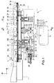
- the conveyor device shown in FIGS. 1 to 3 is used to transport cartridges through a filling station, in which the cartridges are filled with a pasty, ie non-flowable material. They are placed horizontally, i.e. transported and filled in a horizontal position.
- a filling station in which this conveyor device can be used, is known for example from EP 0 290 747 B1 (corresponding to US Pat. No. 4,874,022).
- the conveyor device has a frame 1 on which a vertical slide 2 is guided in two vertically arranged sliding bearings 3, 4 so as to be displaceable in the vertical y-direction.
- a horizontal conveyor slide 7 designed as a rake is displaceably guided in the horizontal x direction relative to the vertical slide 2.
- An electrical drive motor 8 is also fastened to the frame 1 and drives a cam drive shaft 12 which is likewise mounted in the frame 1 by means of a bearing 11 via a reduction gear 9 designed as a worm gear and a toothed belt drive 10.
- a flange 13 is fastened to the drive shaft 12, on which a cam disk 14 can be centered with respect to the axis of rotation 16 of the drive shaft 12 by means of a centering pin 15 and can be positioned in its angular position with respect to the drive shaft 12 by means of a centering pin 17.
- the actual attachment to the flange 13 is carried out by means of screws 18.
- a roller 20 rests on the circumference 19 of the cam disk 14 and is mounted in a bearing 21 on the underside of the vertical slide 2. As a result, the vertical slide 2 moves once up and down again in one rotation of the cam disk 14 in accordance with the course of its circumference 19; the movement takes place in the y direction.
- a roller 23 rotatably mounted in a tappet 22.
- This tappet 22 is horizontal, on the one hand, in a horizontal sliding bearing 24 connected to the vertical sliding bearing 3 and, secondly, in a spaced apart one from it further fixedly connected to the frame 1 sliding bearing 25 slidably mounted in the x direction.
- the sliding bearing 25 is assigned an abutment 26 for a return spring 27, which in turn is supported against the tappet 22 and presses it with its roller 23 against the circumference 19 of the cam disk 14.
- the return spring 27 is designed as a prestressed compression spring, for example as a spring assembly or as a coil spring, in such a way that the spring characteristic curve is approximately horizontal over the spring travel. The restoring force exerted on the plunger 22 is therefore largely constant over its displacement path.
- a link designed as a double lever 28 is also pivotably mounted by means of a pivot bearing 29 about a horizontal axis extending transversely to the direction of displacement of the plunger 22 and the vertical slide 2, that is to say in the z direction.
- One end of this double lever 28 is coupled by means of an elongated hole guide 30 to a transfer roller 31 mounted on the tappet 22.
- the other upper end of the double lever 28 is provided with a rotatably mounted transfer roller 32 which is supported in an abutment 33 with an elongated hole guide 33a. This abutment 33 is attached to the underside of the horizontal conveyor carriage 7.
- the vertical slot guide 33a is so long that the vertical movements of the vertical carriage 2 carrying the vertical carriage 2 can be carried out without the transfer roller 32 striking the ends of the slot guide 33a.
- the ratio of e / d can also be set by the choice of the transmission ratio a / b.
- a / b e / d .
- the angle between the the direction of movement of the plunger 22 defined as the x direction and the stroke direction of the vertical slide 2 defined as the y direction is 90 °.
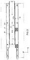
- the vertical slide 2 has two spaced-apart, rake-like side cheeks 34, which are provided with recesses 35 of uniform size and with an identical center spacing f from one another.
- the center distance f between two adjacent recesses 35 which can also be referred to as the pitch, is identical to the delivery stroke d in the x direction.
- the recesses 35 are designed so that they are suitable for receiving cartridges 36.
- the recesses 35 have an extension g in the x direction, which is slightly larger than the diameter h of the cartridges 36.
- the dimension g thus corresponds to the distance between the driver webs 37 delimiting the recesses 35 in the x direction.
- the recesses 35 are formed by down a reason 38.
- web-like supports 39 serving as side guides for the vertical slide 2 are arranged, which are provided with positioning recesses 40 for the cartridges 36.
- the upper side of the supports 39 is defined by two straight-line intermediate sections 40a between each two adjacent positioning recesses 40.
- the positioning recesses 40 also have a center distance f and are arranged such that they are vertically aligned with the recesses 35 and the side cheeks 34 of the vertical slide 2 when the latter is in one of its two end positions.
- the maximum vertical distance i of the base 38 of the recesses 35 in the lower position of the vertical slide 2 from the intermediate sections 40a of the supports 39 is greater than the vertical stroke e of the vertical slide 2, so that the cartridges 36 do not move from the supports 39 can be lifted off.
- the cartridges 36 are transported horizontally, that is to say in a horizontal position, specifically in the z direction, in the x direction. They do not rest on the base 38 of the recesses 35 and lie approximately free of play between two adjacent driver webs 37. They are each pushed by the respective driver web 37 out of a recess 40 via the intermediate section 40a into the adjacent recess 40.
- the cam disk 14 has four peripheral sections. It has an inner quarter-circle section 41 which extends over 90 °. Diametrically to this, it has an outer quarter-circle section 42, which also extends over 90 °.
- the two quarter-circle sections 41 and 42 are connected to one another by two cam flanks 43, 44, each of which likewise extends over 90 °.
- the vertical slide 2 In the initial position shown in FIGS. 1 and 4, the vertical slide 2 is in its lower end position, the horizontal conveyor slide 7 is in its position in the x-direction that is most displaced in the transport direction 45.
- the cam disk 14 rotates counterclockwise in the direction of rotation 46.
- the roller 20 of the vertical slide 2 moves on the inner quarter-circle section 41, ie the vertical slide 2 remains in its lower end position.
- the roller 23 of the plunger 22 is guided over the cam flank 43 leading from the outer quarter-circular section 42 to the inner quarter-circular section 41, ie the plunger 22 is moved in the x direction by the return spring 27, so that the horizontal conveyor slide 7 in its lower position, shown in FIG.
- the roller 20 of the vertical slide 2 is over the outer quarter-circle section 42 out, ie the vertical carriage 2 and thus the horizontal conveyor carriage 7 remains in the upper position.
- the roller 23 of the plunger 22 is guided over the cam flank 44 connecting the inner quarter-circular section 41 to the outer quarter-circular section 42, ie the plunger 22 is deflected against the force of the return spring 27.
- the horizontal conveying slide 7 is moved in the transport direction 45 in the transport direction 45 by a conveying stroke d opposite to the direction of movement of the plunger 22 and takes the cartridges 36 with it in the conveying direction 45 in the transport direction 45.
- the movements described cause a rectangular movement of the horizontal conveyor carriage 7.
- the design of the cam flanks 43, 44 is such that a constant braking takes place at the end points of the movements, so that the cartridges 36 are accelerated and accelerated in the vertical and horizontal directions be slowed down. There is therefore no abrupt acceleration or, in particular, reversal of movement, which could lead to them adopting an incorrect position on the supports 39 or not lying still after being set down.
- the supports 39 ' are in this case designed as smooth rails. Their distance k from the bottom 38 of the recesses 35 is slightly larger than the vertical stroke e with the consequence that the cans 47 are not lifted up from the supports 39 'during the vertical stroke of the horizontal conveyor carriage 7.
- Two driver webs 37 each grip the respective can 47 and move it on the supports 39 'in the transport direction 45.
- the dimensions of the supports 39' and the side walls 34 and the driver webs 37 must of course be adapted to the size of the cans 47.
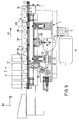
- the conveyor device according to FIGS. 6 to 8 differs from the conveyor device according to FIGS. 1 to 4 in that not only one cam disk but two cam disks are present.
- the same reference numerals have been used in FIGS. 6 to 8 as in FIGS. 1 to 4; In this respect, no further description is required.
- cam disks 14 ′′ and 14 ′′ ′′ are centered on the flange 13 fastened to the drive shaft 12 by means of a centering pin 15 ′′ to the axis of rotation 16 of the drive shaft 12.
- the actual attachment to the flange 13 is carried out by means of screws 18 ′′, which penetrate both cam disks 14 ′′ and 14 ′′ ′′.
- the roller 20, which is mounted in the bearing 21 on the underside of the vertical slide 2 bears against the circumference 19 ′′ of the cam disk 14 ′′. Accordingly, the vertical slide 2 also moves in this conveying device once the cam disk 14 ′′ rotates up and down again in the starting position in accordance with the course of its circumference 19 ′′; the movement also takes place here in the y direction.
- the return spring 27 can also be designed as a pneumatic spring.
- the cam disk 14 ′′ has four peripheral sections. It has an inner quarter-circle section 41 ′′ which extends over 90 °. Diametrically to this, it has an outer quarter-circle section 42 ′′, which also extends over 90 °.
- the two quarter-circle sections 41 ′′ and 42 ′′ are with two cam flanks 43 '' and 44 '' connected to each other, each also extending over 90 °.
- cam disk 14 ′′ ′′ It applies to the cam disk 14 ′′ ′′ that it has an inner quarter circle section 41 ′′ ′′ which extends over 90 °, which is also diametrically opposed to an outer quarter circle section 42 ′′ ′′ which also extends over 90 °.
- These two quarter-circle sections 41 '' 'and 42' '' are also connected to one another with cam flanks 43 '' 'and 44' '' each extending over 90 °.
- the ratio between the conveying stroke d of the horizontal conveying carriage 7 and the vertical stroke e of the vertical carriage 2 can also be influenced by the fact that the stroke c '' of the cam disk 14 '' is configured differently to the stroke c '' 'of the cam disk 14' '', as can be seen in particular from FIG. 8.
- the stroke c '' 'of the cam disk 14' '' is significantly larger than the stroke c '' of the cam disk 14 ''. This means that the stroke c ′′ of the roller 20 of the vertical slide 2 is smaller than the stroke c ′′ ′′ of the roller 23 when the cam disk 14 ′′ is rotated.
Abstract
Description
Die Erfindung betrifft eine Fördervorrichtung nach dem Oberbegriff des Anspruches 1.The invention relates to a conveyor device according to the preamble of
Eine derartige Fördervorrichtung ist aus der EP 0 290 747 B1 (entsprechend US-Patent 4 874 022) bekannt. Sie wird dort in einer Kartuschen-Füll- und Verschließ-Maschine eingesetzt. Der Vertikaltrieb für den rechenartig ausgebildeten Horizontal-Förder-Schlitten ist hierbei durch zwei vertikal angeordnete pneumatisch beaufschlagbare Arbeitszylinder gebildet, die den horizontal verschiebbaren Schlitten vertikal anheben, wodurch Kartuschen von einer Auflage abgehoben werden. Durch einen im wesentlichen horizontal angeordneten pneumatisch beaufschlagbaren Arbeitszylinder wird der Horizontal-Förder-Schlitten mit den Kartuschen horizontal um einen Förderhub vorgegebener Länge weitertransportiert. Anschließend werden die vertikal angeordneten pneumatisch beaufschlagbaren Arbeitszylinder wieder entlastet, so daß der Schlitten abgesenkt und die Kartuschen wieder auf der Auflage abgesetzt werden. Der rechenartig ausgebildete Schlitten wird dann mittels des horizontal angeordneten Arbeitszylinders wieder in seine rückwärtige Ausgangsstellung zurückbewegt. Mit diesen pneumatisch beaufschlagbaren Arbeitszylindern wird eine Rechteck-Bewegung des Horizontal-Förder-Schlittens erzeugt, wobei die Kartuschen getaktet jeweils um einen vorgegebenen horizontalen Förderhub weitertransportiert werden. Die geschilderten Antriebe sind in ihrem Beschleunigungs- und Bremsverhalten zu hart. Es erfolgt jeweils ein abruptes Absetzen der Kartuschen auf den Auflagen, so daß die Kartuschen erst nach einer gewissen Zeit mit Sicherheit ruhig liegen. Wenn die Kartuschen nicht ruhig liegen, so kann dies beispielsweise in einer Arbeitsstation zu Schwierigkeiten führen, in der in die bereits mit pastösem Material gefüllten Kartuschen Auspreßkolben eingesetzt werden. Im übrigen macht der Antrieb mittels der pneumatisch beaufschlagbaren Arbeitszylinder hohe Taktzeiten notwendig.Such a conveyor device is known from EP 0 290 747 B1 (corresponding to US Pat. No. 4,874,022). It is used there in a cartridge filling and closing machine. The vertical drive for the rake-shaped horizontal conveyor slide is formed by two vertically arranged pneumatically actuated working cylinders, which lift the horizontally displaceable slide vertically, whereby cartridges are lifted from a support. The horizontal conveying slide with the cartridges is transported horizontally by a conveying stroke of a predetermined length by means of an essentially horizontally arranged pneumatically actuated working cylinder. Then the vertically arranged, pneumatically actuated working cylinders are relieved again, so that the carriage is lowered and the cartridges are placed back on the support. The rake-shaped slide is then moved back into its rearward starting position by means of the horizontally arranged working cylinder. With these pneumatically actuated working cylinders, a rectangular movement of the horizontal conveying slide is generated, the cartridges being transported in a clocked manner in each case by a predetermined horizontal conveying stroke. The described drives are too hard in their acceleration and braking behavior. There is an abrupt deposition of the cartridges on the supports, so that the cartridges only rest with certainty after a certain time. If the Cartridges are not lying still, this can lead to difficulties, for example, in a work station in which squeezing pistons are inserted into the cartridges which are already filled with pasty material. In addition, the drive by means of the pneumatically actuated working cylinders necessitates high cycle times.
Auch bei Dosen-Füll- und Verschließ-Maschinen, wie sie beispielsweise aus der EP 0 019 646 B1 (entsprechend US-Patent 4 221 102) bekannt sind, in denen flüssige Farben od.dgl. in Dosen abgefüllt werden, sind die geschilderten taktweise arbeitenden Fördervorrichtungen von Nachteil, da durch das abrupte Beschleunigen bzw. Abbremsen die niedrigviskosen Flüssigkeiten über den Rand der Dose schwappen können.Also in the case of can filling and sealing machines, as are known, for example, from EP 0 019 646 B1 (corresponding to US Pat. No. 4,221,102), in which liquid colors or the like. are filled into cans, the cyclical conveying devices described are disadvantageous because the abrupt acceleration or deceleration can cause the low-viscosity liquids to spill over the edge of the can.
Aus der DE-OS 19 40 287 ist eine automatische Abfüll- und Verschließmaschine bekannt. Der Vertikalantrieb erfolgt hierbei mittels zweier Nockenscheiben. Der Horizontalantrieb erfolgt mittels eines gesonderten Kurbeltriebes. Diese Ausgestaltung ist zumindest sehr aufwendig.An automatic filling and closing machine is known from DE-OS 19 40 287. The vertical drive takes place here by means of two cam disks. The horizontal drive takes place by means of a separate crank drive. This configuration is at least very complex.
Aus der DE 34 01 704 C1 ist eine Vorschubeinrichtung zum schrittweisen Werkstücktransport bekannt, bei der im Abstand voneinander Greiferschienen vorgesehen sind, die in Vorschubrichtung gemeinsam vor- und zurückbewegbar sind und die quer zu ihrer Längserstreckung gegenläufig antreibbar sind. Der Antrieb der Greiferschienen ist von einer einzigen umlaufend angetriebenen Kurvenscheibe abgeleitet.From DE 34 01 704 C1 a feed device for step-by-step workpiece transport is known, in which gripper rails are provided at a distance from one another, which can be moved back and forth together in the feed direction and which can be driven in opposite directions transversely to their longitudinal extent. The drive of the gripper rails is derived from a single rotating cam.
Der Erfindung liegt die Aufgabe zugrunde, eine taktweise arbeitende Fördervorrichtung der gattungsgemäßen Art so auszugestalten, daß mit einfachen Mitteln weiche Förderbewegungen bei niedrigen Taktzeiten erreicht werden.The invention has for its object to design a cyclically operating conveyor device of the generic type so that soft conveying movements can be achieved at low cycle times with simple means.
Diese Aufgabe wird erfindungsgemäß durch die Merkmale im Kennzeichnungsteil des Anspruches 1 gelöst. Der Kern der Erfindung liegt darin, daß der Horizontaltrieb und der Vertikaltrieb des Horizontal-Förder-Schlittens von mindestens einer Nockenscheibe abgeleitet werden, mittels derer eine Rechteck-Bewegung des Horizontal-Förder-Schlittens erzeugt wird. Die Nockenflanken der mindestens einen Nockenscheibe können so gestaltet werden, daß am Beginn einer Bewegung und am Ende einer Bewegung jeweils die Beschleunigung bzw. die Abbremsung sehr weich erfolgt. Dazwischen kann mit hoher Geschwindigkeit gefahren werden. Die Behälter, beispielsweise Kartuschen oder Dosen liegen bzw. stehen am Ende eines Förderhubes ruhig, so daß sich sofort ein Arbeitsvorgang anschließen kann. Die Vertikalbewegung und die Horizontalbewegung werden mit einem Phasenversatz von 90° von derselben Nockenscheibe abgeleitet. Es ist ausgeschlossen, daß durch eine Störung gleichzeitig eine Horizontal- und eine Vertikal-Bewegung stattfindet. Es hat sich gezeigt, daß die Taktzeiten gegenüber der bekannten Ausgestaltung um 30% gesenkt werden können.This object is achieved by the features in the characterizing part of
Zahlreiche vorteilhafte und zum Teil erfinderische Ausgestaltungen ergeben sich aus den Unteransprüchen.Numerous advantageous and partly inventive embodiments result from the subclaims.
Weitere Merkmale, Vorteile und Einzelheiten der Erfindung ergeben sich im übrigen aus der Beschreibung von Ausführungsbeispielen anhand der Zeichnungen. Es zeigt
- Fig. 1
- eine Fördervorrichtung nach der Erfindung zum taktweisen Transport von liegenden Kartuschen im Vertikal-Längs-Schnitt,
- Fig. 2
- eine Draufsicht auf die Vorrichtung nach Fig. 1,
- Fig. 3
- einen vertikalen Querschnitt durch die Vorrichtung gemäß der Schnittlinie III-III in Fig. 1,
- Fig. 4
- eine Nockenscheibe in Draufsicht,
- Fig. 5
- eine Fördervorrichtung nach der Erfindung zum Transport von Dosen in einer Fig. 1 entsprechenden Darstellung,
- Fig. 6
- eine Fördervorrichtung mit zwei Nockenscheiben zum taktweisen Transport von liegenden Kartuschen im Vertikal-Längs-Schnitt,
- Fig. 7
- einen vertikalen Querschnitt durch die Fördervorrichtung nach Fig. 6 gemäß der Schnittlinie VII-VII in Fig. 6 und
- Fig. 8
- die beiden Nockenscheiben der Fördervorrichtung nach den Fig. 6 und 7 in Draufsicht.
- Fig. 1
- a conveyor device according to the invention for the cyclical transport of lying cartridges in a vertical longitudinal section,
- Fig. 2
- 2 shows a top view of the device according to FIG. 1,
- Fig. 3
- 2 shows a vertical cross section through the device according to section line III-III in FIG. 1,
- Fig. 4
- a cam disc in top view,
- Fig. 5
- 2 shows a conveyor device according to the invention for transporting cans in a representation corresponding to FIG. 1,
- Fig. 6
- a conveyor device with two cam discs for the cyclical transport of lying cartridges in a vertical longitudinal section,
- Fig. 7
- a vertical cross section through the conveyor device of FIG. 6 along the section line VII-VII in Fig. 6 and
- Fig. 8
- the two cams of the conveyor device according to FIGS. 6 and 7 in plan view.
Die in den Fig. 1 bis 3 dargestellte Fördervorrichtung dient zum Transport von Kartuschen durch eine Abfüllstation, in der die Kartuschen mit einem pastösen, also nicht fließfähigen Material gefüllt werden. Sie werden hierbei in liegender, d.h. horizontaler Lage transportiert und gefüllt. Eine solche Abfüllstation, in der diese Fördervorrichtung einsetzbar ist, ist beispielsweise aus der EP 0 290 747 B1 (entsprechend US-Patent 4 874 022) bekannt.The conveyor device shown in FIGS. 1 to 3 is used to transport cartridges through a filling station, in which the cartridges are filled with a pasty, ie non-flowable material. They are placed horizontally, i.e. transported and filled in a horizontal position. Such a filling station, in which this conveyor device can be used, is known for example from EP 0 290 747 B1 (corresponding to US Pat. No. 4,874,022).
Die Fördervorrichtung weist ein Gestell 1 auf, auf dem ein Vertikal-Schlitten 2 in zwei vertikal angeordneten Schiebelagern 3, 4 in vertikaler y-Richtung verschiebbar geführt ist. Auf dem Vertikal-Schlitten 2 sind zwei horizontale Führungs-Lager 5, 6 angebracht, in denen ein als Rechen ausgebildeter Horizontal-Förder-Schlitten 7 in horizontaler x-Richtung gegenüber dem Vertikal-Schlitten 2 verschiebbar geführt ist.The conveyor device has a
Am Gestell 1 ist weiterhin ein elektrischer Antriebs-Motor 8 befestigt, der über ein als Schneckengetriebe ausgebildetes Untersetzungsgetriebe 9 und einen Zahnriementrieb 10 eine ebenfalls im Gestell 1 mittels eines Lagers 11 gelagerte Nocken-Antriebswelle 12 antreibt. An der Antriebswelle 12 ist ein Flansch 13 befestigt, auf dem eine Nockenscheibe 14 mittels eines Zentrierzapfens 15 zur Drehachse 16 der Antriebswelle 12 zentriert und mittels eines Zentrierstiftes 17 in ihrer Winkellage zur Antriebswelle 12 positioniert werden kann. Die eigentliche Befestigung am Flansch 13 erfolgt mittels Schrauben 18. Am Umfang 19 der Nockenscheibe 14 liegt eine Rolle 20 an, die in einem Lager 21 an der Unterseite des Vertikal-Schlittens 2 gelagert ist. Demzufolge bewegt sich der Vertikal-Schlitten 2 bei einer Umdrehung der Nockenscheibe 14 entsprechend dem Verlauf ihres Umfangs 19 einmal nach oben und wieder nach unten in die Ausgangsstellung zurück; die Bewegung erfolgt also in y-Richtung.An
Gegen den Umfang 19 der Nockenscheibe 14 liegt weiterhin eine in einem Stößel 22 drehbar gelagerte Rolle 23 an. Dieser Stößel 22 ist horizontal zum einen in einem mit dem vertikalen Schiebelager 3 verbundenen horizontalen Schiebelager 24 und zum zweiten in einem hiervon beabstandeten weiteren ortsfest mit dem Gestell 1 verbundenen Schiebelager 25 in x-Richtung verschiebbar gelagert. Dem Schiebelager 25 ist ein Widerlager 26 für eine Rückstellfeder 27 zugeordnet, die sich wiederum gegen den Stößel 22 abstützt und diesen mit seiner Rolle 23 gegen den Umfang 19 der Nockenscheibe 14 drückt. Die Rückstellfeder 27 ist als vorgespannte Druckfeder, beispielsweise als ein Federpaket oder als Schraubenfeder ausgebildet, und zwar in der Weise, daß die Federkennlinie über dem Federweg angenähert waagerecht verläuft. Die auf den Stößel 22 ausgeübte Rückstellkraft ist also über dessen Verschiebeweg weitgehend konstant.Against the
Am Gestell 1 ist weiterhin ein als Doppelhebel 28 ausgebildeter Lenker mittels eines Schwenklagers 29 schwenkbar um eine horizontale, quer zur Verschieberichtung des Stößels 22 und des Vertikal-Schlittens 2, also in z-Richtung, verlaufende Achse schwenkbar gelagert. Ein Ende dieses Doppelhebels 28 ist mittels einer Langlochführung 30 mit einer am Stößel 22 gelagerten Übertragungsrolle 31 gekoppelt. Das andere obere Ende des Doppelhebels 28 ist mit einer drehbar gelagerten Übertragungsrolle 32 versehen, die in einem Widerlager 33 mit Langlochführung 33a abgestützt ist. Dieses Widerlager 33 ist an der Unterseite des Horizontal-Förder-Schlittens 7 angebracht. Bei horizontalen Bewegungen des Stößels 22 aufgrund der Umdrehungen der Nockenscheibe 14 wird der Horizontal-Förder-Schlitten 7 mittels des Doppelhebels 28 jeweils gegensinnig horizontal verschoben. Die vertikale Langlochführung 33a ist hierbei so lang ausgebildet, daß die Vertikalbewegungen des den Horizontal-Förder-Schlitten 7 tragenden Vertikal-Schlittens 2 ausgeführt werden können, ohne daß die Übertragungsrolle 32 an den Enden der Langlochführung 33a anschlägt. Durch eine geeignete Wahl des Abstandes a zwischen der Achse der Übertragungsrolle 31 und der Achse des Schwenklagers 29 einerseits und des Abstandes b zwischen der Achse der Übertragungsrolle 32 und der Achse des Schwenklagers 29 kann eine Übersetzung zwischen dem Hub c der Nockenscheibe 14 und damit auch des Stößels 22 einerseits und dem Förderhub d des Horizontal-Förder-Schlittens 7 festgelegt werden. Da der Hub c der Nockenscheibe 14 auch gleich dem vertikalen Hub e des Vertikal-Schlittens 2 und damit des Horizontal-Förder-Schlittens 7 ist, kann somit durch die Wahl des Übersetzungsverhältnisses a/b auch das Verhältnis von e/d eingestellt werden. Es gilt: ![]()
![]()
Wie den Fig. 2 und 3 entnehmbar ist, weist der Vertikal-Schlitten 2 zwei im Abstand voneinander angeordnete, rechenartig ausgebildete Seitenwangen 34 auf, die mit Ausnehmungen 35 in gleichmäßiger Größe und mit identischem Mittenabstand f voneinander versehen sind. Der Mittenabstand f zweier benachbarter Ausnehmungen 35, der auch als die Teilung bezeichnet werden kann, ist identisch dem Förderhub d in x-Richtung. Die Ausnehmungen 35 sind so ausgebildet, daß sie zur Aufnahme von Kartuschen 36 geeignet sind. Die Ausnehmungen 35 weisen hierzu eine Erstreckung g in x-Richtung auf, die geringfügig größer ist als der Durchmesser h der Kartuschen 36. Das Maß g entspricht also dem Abstand der die Ausnehmungen 35 in x-Richtung begrenzenden Mitnehmerstege 37. Die Ausnehmungen 35 werden durch einen Grund 38 nach unten begrenzt.As can be seen from FIGS. 2 and 3, the
Beiderseits der Seitenwangen 34 des Vertikal-Schlittens 2 sind als Seitenführungen für den Vertikal-Schlitten 2 dienende stegartige Auflagen 39 angeordnet, die mit Positionier-Ausnehmungen 40 für die Kartuschen 36 versehen sind. Zwischen jeweils zwei benachbarten Positionier-Ausnehmungen 40 wird die Oberseite der Auflagen 39 durch geradlinige Zwischenabschnitte 40a definiert. Die Positionier-Ausnehmungen 40 weisen ebenfalls einen Mittenabstand f auf und sind derart angeordnet, daß sie vertikal mit den Ausnehmungen 35 und den Seitenwangen 34 des Vertikal-Schlittens 2 fluchten, wenn dieser sich in einer seiner beiden Endstellungen befindet. Der maximale vertikale Abstand i des Grundes 38 der Ausnehmungen 35 in der unteren Stellung des Vertikal-Schlittens 2 von den Zwischenabschnitten 40a der Auflagen 39 ist größer als der vertikale Hub e des Vertikal-Schlittens 2, so daß die Kartuschen 36 nicht von den Auflagen 39 abgehoben werden können. Die Kartuschen 36 werden liegend, also in horizontaler Lage, und zwar in z-Richtung liegend, in x-Richtung schrittweise transportiert. Sie liegen hierbei nicht auf dem Grund 38 der Ausnehmungen 35 auf und liegen angenähert spielfrei zwischen zwei benachbarten Mitnehmerstegen 37. Sie werden vom jeweiligen Mitnehmersteg 37 jeweils aus einer Ausnehmung 40 über den Zwischenabschnitt 40a in die benachbarte Ausnehmung 40 geschoben.On both sides of the
Wie aus Fig. 4 hervorgeht, weist die Nockenscheibe 14 vier Umfangsabschnitte auf. Sie weist einen inneren Viertel-Kreisabschnitt 41 auf, der sich über 90° erstreckt. Diametral hierzu weist sie einen äußeren Viertel-Kreisabschnitt 42 auf, der sich ebenfalls über 90° erstreckt. Die beiden Viertel-Kreisabschnitte 41 und 42 sind mit zwei Nockenflanken 43, 44 miteinander verbunden, die sich jeweils ebenfalls über 90° erstrecken.As can be seen from FIG. 4, the
Die Hub- und Förderbewegung des Vertikal-Schlittens 2 einerseits und des Horizontal-Förder-Schlittens 7 wird nachfolgend unter Bezugnahme auf die Umlaufbewegung der Nockenscheibe 14 beschrieben:The lifting and conveying movement of the
In der in der Fig. 1 und 4 dargestellten Ausgangsstellung befindet sich der Vertikal-Schlitten 2 in seiner unteren Endlage, der Horizontal-Förder-Schlitten 7 befindet sich in seiner in x-Richtung am weitesten in der Transportrichtung 45 verschobenen Stellung. Die Nockenscheibe 14 dreht sich in Drehrichtung 46 entgegen dem Uhrzeigersinn. Bei einer ersten Vierteldrehung der Nockenscheibe 14 aus der in Fig. 1 dargestellten Stellung heraus bewegt sich die Rolle 20 des Vertikal-Schlittens 2 auf dem inneren Viertel-Kreisabschnitt 41, d.h. der Vertikal-Schlitten 2 verbleibt in seiner unteren Endlage. Die Rolle 23 des Stößels 22 wird über die vom äußeren Viertel-Kreisabschnitt 42 zum inneren Viertel-Kreisabschnitt 41 führende Nockenflanke 43 geführt, d.h. der Stößel 22 wird durch die Rückstellfeder 27 in x-Richtung bewegt, so daß der Horizontal-Förder-Schlitten 7 in seiner unteren, in Fig. 1 dargestellten Lage entgegen der Transportrichtung 45 um einen Förderhub d bewegt wird. Im Verlaufe der nächsten (zweiten) Vierteldrehung der Nockenscheibe 14 rollt die Rolle 20 über die den inneren Viertel-Kreisabschnitt 41 mit dem äußeren Viertel-Kreisabschnitt 42 verbindende Nockenflanke 44 ab, d.h. der Vertikal-Schlitten 2 wird um den vertikalen Hub e angehoben. Hierbei werden die auf der Auflage 39 aufliegenden Kartuschen 36 von den Ausnehmungen 35 aufgenommen, so daß sie von den Mitnehmerstegen 37 in eine benachbarte Positionier-Ausnehmung 40 verschoben werden. Da während dieser Vierteldrehung der Nockenscheibe 14 die Rolle 23 des Stößels 22 über den inneren Viertel-Kreisabschnitt 41 der Nockenscheibe 14 abrollt, verbleibt der Horizontal-Förder-Schlitten 7 während dieser Vertikalbewegung des Vertikal-Schlittens 2 in Ruhe. Bei der anschließenden dritten Vierteldrehung der Nockenscheibe 14 wird die Rolle 20 des Vertikal-Schlittens 2 über den äußeren Viertel- Kreisabschnitt 42 geführt, d.h. der Vertikal-Schlitten 2 und damit der Horizontal-Förder-Schlitten 7 verbleibt in der oberen Stellung. Gleichzeitig wird die Rolle 23 des Stößels 22 über die den inneren Viertel-Kreisabschnitt 41 mit dem äußeren Viertel-Kreisabschnitt 42 verbindende Nockenflanke 44 geführt, d.h. der Stößel 22 wird gegen die Kraft der Rückstellfeder 27 ausgelenkt. Hierdurch wird der Horizontal-Förder-Schlitten 7 entgegengesetzt zur Bewegungsrichtung des Stößels 22 in Transportrichtung 45 um einen Förderhub d bewegt und nimmt hierbei die Kartuschen 36 um den Förderhub d in Transportrichtung 45 mit. Im Anschluß daran bewegt sich bei der nächsten (vierten) Vierteldrehung der Nockenscheibe 14 die Rolle 20 über die den äußeren Viertel-Kreisabschnitt 42 mit dem inneren Viertel-Kreisabschnitt 41 verbindende Nockenflanke 43, d.h. der Vertikal-Schlitten 2 wird durch sein Eigengewicht vertikal nach unten geführt. Da sich die Rolle 23 des Stößels 22 während dieser Vierteldrehung der Nockenscheibe 14 auf dem äußeren Viertel-Kreisabschnitt 42 bewegt, verbleibt der Horizontal-Förder-Schlitten 7 in seiner Ruhelage. Bei der vertikalen Abwärtsbewegung des Vertikal-Schlitten 2 werden daher die Seitenwangen 34 so weit nach unten weggefahren, daß ihre Mitnehmerstege 37 sich unterhalb der Positionier-Ausnehmungen 40 und damit unterhalb der Kartuschen 36 befinden, so daß sie anschließend unterhalb der Kartuschen 36 bei der nächsten (ersten) Vierteldrehung der Nockenscheibe 14 wieder zurückverfahren werden können.In the initial position shown in FIGS. 1 and 4, the
Die geschilderten Bewegungen bewirken eine Rechteckbewegung des Horizontal-Förder-Schlittens 7. Die Gestaltung der Nockenflanken 43, 44 ist derart, daß jeweils an den Endpunkten der Bewegungen eine stetige Abbremsung stattfindet, so daß die Kartuschen 36 in vertikaler und in horizontaler Richtung stetig beschleunigt und abgebremst werden. Es erfolgt also keine abrupte Beschleunigung oder insbesondere Bewegungsumkehr, die dazu führen könnte, daß sie auf den Auflagen 39 eine Fehlposition einnehmen oder aber nach dem Absetzen nicht ruhig liegen.The movements described cause a rectangular movement of the
In Fig. 5 ist angedeutet, wie mit der geschilderten Fördervorrichtung stehende Behälter, beispielsweise mit flüssigem Material zu füllende Dosen 47 transportiert werden können. Die Auflagen 39' sind in diesem Fall als glatte Schienen ausgebildet. Ihr Abstand k vom Grund 38 der Ausnehmungen 35 ist etwas größer als der vertikale Hub e mit der Konsequenz, daß die Dosen 47 beim Vertikalhub des Horizontal-Förder-Schlittens 7 nach oben nicht von den Auflagen 39' abgehoben werden. Jeweils zwei Mitnehmerstege 37 ergreifen die jeweilige Dose 47 und verschieben sie auf den Auflagen 39' in Transportrichtung 45. Die Abmessungen der Auflagen 39' und der Seitenwangen 34 und der Mitnehmerstege 37 müssen selbstverständlich der Größe der Dosen 47 angepaßt werden.5 indicates how standing containers, for
Die Fördervorrichtung nach den Fig. 6 bis 8 unterscheidet sich von der Fördervorrichtung nach den Fig. 1 bis 4 dadurch, daß nicht nur eine Nockenscheibe, sondern zwei Nockenscheiben vorhanden sind. Insoweit als die Fördervorrichtungen identisch sind, sind in den Figuren 6 bis 8 dieselben Bezugszeichen wie in den Fig. 1 bis 4 verwendet worden; es bedarf insoweit keiner erneuten Beschreibung.The conveyor device according to FIGS. 6 to 8 differs from the conveyor device according to FIGS. 1 to 4 in that not only one cam disk but two cam disks are present. Insofar as the conveying devices are identical, the same reference numerals have been used in FIGS. 6 to 8 as in FIGS. 1 to 4; In this respect, no further description is required.
Auf dem an der Antriebswelle 12 befestigten Flansch 13 sind zwei Nockenscheiben 14'' und 14''' mittels eines Zentrierzapfens 15'' zur Drehachse 16 der Antriebswelle 12 zentriert. Die eigentliche Befestigung am Flansch 13 erfolgt mittels Schrauben 18'', die beide Nockenscheiben 14'' und 14''' durchsetzen. Am Umfang 19'' der Nockenscheibe 14'' liegt die Rolle 20 an, die in dem Lager 21 an der Unterseite des Vertikal-Schlittens 2 gelagert ist. Demzufolge bewegt sich auch bei dieser Fördervorrichtung der Vertikal-Schlitten 2 bei einer Umdrehung der Nockenscheibe 14'' entsprechend dem Verlauf ihres Umfangs 19'' einmal nach oben und wieder nach unten in die Ausgangsstellung zurück; die Bewegung erfolgt also auch hierbei in y-Richtung.Two
Gegen den Umfang 19''' der Nockenscheibe 14''' liegt die in dem Stößel 22 drehbar gelagerte Rolle 23 an. Die Rückstellfeder 27 kann bei diesem Ausführungsbeispiel und in gleicher Weise bei dem Ausführungsbeispiel nach den Fig. 1 bis 3 auch als pneumatische Feder ausgebildet sein.The
Wie aus Fig. 8 hervorgeht, weist die Nockenscheibe 14'' vier Umfangsabschnitte auf. Sie weist einen inneren Viertel-Kreisabschnitt 41'' auf, der sich über 90° erstreckt. Diametral hierzu weist sie einen äußeren Viertel-Kreisabschnitt 42'' auf, der sich ebenfalls über 90° erstreckt. Die beiden Viertel-Kreisabschnitte 41'' und 42'' sind mit zwei Nockenflanken 43'' und 44'' miteinander verbunden, die sich jeweils ebenfalls über 90° erstrecken.As can be seen from FIG. 8, the
Für die Nockenscheibe 14''' gilt, daß sie einen inneren Viertel-Kreisabschnitt 41''' aufweist der sich über 90° erstreckt, dem ein sich ebenfalls über 90° erstreckender äußerer Viertel-Kreisabschnitt 42''' diametral gegenüberliegt. Auch diese beiden Viertel-Kreisabschnitte 41''' und 42''' sind mit sich jeweils über 90° erstreckenden Nockenflanken 43''' und 44''' miteinander verbunden.It applies to the
Bei dieser Fördervorrichtung nach den Fig. 6 bis 8 kann das Verhältnis zwischen dem Förderhub d des Horizontal-Förder-Schlittens 7 und dem vertikalen Hub e des Vertikal-Schlittens 2 auch dadurch beeinflußt werden, daß der Hub c'' der Nockenscheibe 14'' unterschiedlich zum Hub c''' der Nockenscheibe 14''' ausgestaltet wird, wie es insbesondere aus der Fig. 8 hervorgeht. Im vorliegenden Fall ist der Hub c''' der Nockenscheibe 14''' deutlich größer als der Hub c'' der Nockenscheibe 14''. Dies bedeutet, daß der Hub c'' der Rolle 20 des Vertikal-Schlittens 2 bei einer Umdrehung der Nockenscheibe 14'' kleiner ist als der Hub c''' der Rolle 23.6 to 8, the ratio between the conveying stroke d of the horizontal conveying
Da die beiden Nockenscheiben 14'' und 14''' fest miteinander gekoppelt sind und somit synchron umlaufen, ist die Hub- und Förderbewegung des Vertikal-Schlittens 2 einerseits und des Horizontal-Förder-Schlittens 7 andererseits in ihrem zeitlichen Verlauf gleich derjenigen bei der Fördervorrichtung nach den Fig. 1 bis 4.Since the two
Claims (10)
Applications Claiming Priority (2)
| Application Number | Priority Date | Filing Date | Title |
|---|---|---|---|
| DE19944419498 DE4419498A1 (en) | 1994-06-03 | 1994-06-03 | Conveyor for the cyclical transport of containers |
| DE4419498 | 1994-06-03 |
Publications (1)
| Publication Number | Publication Date |
|---|---|
| EP0685396A1 true EP0685396A1 (en) | 1995-12-06 |
Family
ID=6519753
Family Applications (1)
| Application Number | Title | Priority Date | Filing Date |
|---|---|---|---|
| EP95107101A Withdrawn EP0685396A1 (en) | 1994-06-03 | 1995-05-11 | Conveying device for intermittently conveying containers |
Country Status (3)
| Country | Link |
|---|---|
| EP (1) | EP0685396A1 (en) |
| JP (1) | JPH07330130A (en) |
| DE (1) | DE4419498A1 (en) |
Cited By (10)
| Publication number | Priority date | Publication date | Assignee | Title |
|---|---|---|---|---|
| WO2001060720A1 (en) * | 2000-02-15 | 2001-08-23 | Corob S.P.A. | A system for transporting containers, which is especially suitable for use in a plant for the production of paints, varnishes and the like |
| CN105173661A (en) * | 2015-09-02 | 2015-12-23 | 铁王数控机床(苏州)有限公司 | Efficient isometric feeding conveyor |
| CN105775697A (en) * | 2016-04-15 | 2016-07-20 | 长沙知元科技有限公司 | Stepping type bottle conveying mechanism, bottling machine and packaging equipment |
| WO2017001286A1 (en) * | 2015-06-29 | 2017-01-05 | Tetra Laval Holdings & Finance S.A. | An apparatus for transporting blanks and a method thereof |
| CN107617694A (en) * | 2017-09-13 | 2018-01-23 | 龙口市蓝牙数控装备有限公司 | A kind of cylindrical work conveying device |
| CN108928625A (en) * | 2018-08-27 | 2018-12-04 | 温州海航机械有限公司 | A kind of injection molding tableware collator |
| CN110479529A (en) * | 2019-08-19 | 2019-11-22 | 安徽万马装饰工程有限公司 | A kind of spray painting transfer device for surfactant conveyance conduit |
| CN110498256A (en) * | 2019-07-16 | 2019-11-26 | 苏州翌恒生物科技有限公司 | A kind of eccentric wheel moving-out device for heparin tube |
| WO2021228535A1 (en) * | 2020-05-11 | 2021-11-18 | BüHLER GMBH | Modular plant for producing food products |
| CN115231275A (en) * | 2022-07-29 | 2022-10-25 | 铜陵龙嘉机电有限公司 | Conveying device for capacitor aluminum shell production line |
Families Citing this family (5)
| Publication number | Priority date | Publication date | Assignee | Title |
|---|---|---|---|---|
| DE10021205C2 (en) * | 2000-04-29 | 2002-07-18 | Vetter & Co Apotheker | Device for transporting essentially conical product components in the manufacturing process |
| DE10035957C2 (en) * | 2000-07-21 | 2002-08-22 | Imi Norgren Automotive Gmbh | Push-step conveyor and method for aligning eccentric material |
| KR100880031B1 (en) * | 2007-04-17 | 2009-01-22 | 츠바키 야마큐 체인 가부시키가이샤 | Xy-actuator |
| CN107777643A (en) * | 2016-08-29 | 2018-03-09 | 李萍燕 | A kind of bottle placer |
| CN112008397B (en) * | 2020-08-31 | 2021-08-24 | 乐清野岛机电有限公司 | Online automatic assembly and detection device of electrical alarm module |
Citations (7)
| Publication number | Priority date | Publication date | Assignee | Title |
|---|---|---|---|---|
| DE1940287A1 (en) | 1968-08-13 | 1970-07-30 | J De Vree & Co N V | Automatic filling and sealing machine |
| US4151907A (en) * | 1976-06-16 | 1979-05-01 | Moorfeed Corporation | Walking beam conveyor |
| US4221102A (en) | 1979-07-02 | 1980-09-09 | Ludwig Schwerdtel Gmbh | Apparatus for sealing cans with lids under vacuum |
| EP0068602A1 (en) * | 1981-06-18 | 1983-01-05 | Anderson-Cook, Inc. | Cam actuated loader for forming machine |
| EP0019646B1 (en) | 1979-05-30 | 1983-02-23 | Ludwig Schwerdtel GmbH. | Apparatus for closing boxes under vacuum with a lid |
| DE3401704C1 (en) | 1984-01-19 | 1985-04-11 | Günter 7500 Karlsruhe Zierpka | Feed device for the stepwise transport of materials and/or workpieces, particularly in presses |
| US4874022A (en) | 1987-05-14 | 1989-10-17 | Ludwig Schwerdtel Gmbh | Filling station for a cartridge filling and sealing machine |
Family Cites Families (3)
| Publication number | Priority date | Publication date | Assignee | Title |
|---|---|---|---|---|
| DE1049287B (en) * | 1959-01-22 | Farbwerke Hoechst Aktiengesell schaft vormals Meister Lucius a Brunmg Frankfurt/M | Process for the production of coal and shaped raphite bodies | |
| US4285187A (en) * | 1979-10-31 | 1981-08-25 | Schjeldahl Gilmore T | Intermittent feed mechanism for stacked containers |
| JPS5861931A (en) * | 1981-10-08 | 1983-04-13 | Komatsu Ltd | Material carrying stroke change-over device for transfer feeder |
-
1994
- 1994-06-03 DE DE19944419498 patent/DE4419498A1/en not_active Withdrawn
-
1995
- 1995-05-11 EP EP95107101A patent/EP0685396A1/en not_active Withdrawn
- 1995-05-29 JP JP13049995A patent/JPH07330130A/en active Pending
Patent Citations (8)
| Publication number | Priority date | Publication date | Assignee | Title |
|---|---|---|---|---|
| DE1940287A1 (en) | 1968-08-13 | 1970-07-30 | J De Vree & Co N V | Automatic filling and sealing machine |
| US4151907A (en) * | 1976-06-16 | 1979-05-01 | Moorfeed Corporation | Walking beam conveyor |
| EP0019646B1 (en) | 1979-05-30 | 1983-02-23 | Ludwig Schwerdtel GmbH. | Apparatus for closing boxes under vacuum with a lid |
| US4221102A (en) | 1979-07-02 | 1980-09-09 | Ludwig Schwerdtel Gmbh | Apparatus for sealing cans with lids under vacuum |
| EP0068602A1 (en) * | 1981-06-18 | 1983-01-05 | Anderson-Cook, Inc. | Cam actuated loader for forming machine |
| DE3401704C1 (en) | 1984-01-19 | 1985-04-11 | Günter 7500 Karlsruhe Zierpka | Feed device for the stepwise transport of materials and/or workpieces, particularly in presses |
| US4874022A (en) | 1987-05-14 | 1989-10-17 | Ludwig Schwerdtel Gmbh | Filling station for a cartridge filling and sealing machine |
| EP0290747B1 (en) | 1987-05-14 | 1992-05-27 | Ludwig Schwerdtel GmbH. | Filling station for a cartridge filling and closing machine |
Cited By (15)
| Publication number | Priority date | Publication date | Assignee | Title |
|---|---|---|---|---|
| US6761260B2 (en) | 2000-02-15 | 2004-07-13 | Corob S.P.A. | System for transporting containers, which is especially suitable for use in a plant for the production of paints, varnishes and the like |
| AU2001234086B2 (en) * | 2000-02-15 | 2005-05-12 | Corob S.P.A. | A system for transporting containers, which is especially suitable for use in a plant for the production of paints, varnishes and the like |
| WO2001060720A1 (en) * | 2000-02-15 | 2001-08-23 | Corob S.P.A. | A system for transporting containers, which is especially suitable for use in a plant for the production of paints, varnishes and the like |
| WO2017001286A1 (en) * | 2015-06-29 | 2017-01-05 | Tetra Laval Holdings & Finance S.A. | An apparatus for transporting blanks and a method thereof |
| CN107735324A (en) * | 2015-06-29 | 2018-02-23 | 利乐拉瓦尔集团及财务有限公司 | For conveying the devices and methods therefor of blank |
| CN105173661B (en) * | 2015-09-02 | 2018-02-23 | 铁王数控机床(苏州)有限公司 | A kind of efficiently equidistant feed conveyor |
| CN105173661A (en) * | 2015-09-02 | 2015-12-23 | 铁王数控机床(苏州)有限公司 | Efficient isometric feeding conveyor |
| CN105775697A (en) * | 2016-04-15 | 2016-07-20 | 长沙知元科技有限公司 | Stepping type bottle conveying mechanism, bottling machine and packaging equipment |
| CN107617694A (en) * | 2017-09-13 | 2018-01-23 | 龙口市蓝牙数控装备有限公司 | A kind of cylindrical work conveying device |
| CN108928625A (en) * | 2018-08-27 | 2018-12-04 | 温州海航机械有限公司 | A kind of injection molding tableware collator |
| CN108928625B (en) * | 2018-08-27 | 2023-10-13 | 温州海航机械有限公司 | Injection molding tableware finishing machine |
| CN110498256A (en) * | 2019-07-16 | 2019-11-26 | 苏州翌恒生物科技有限公司 | A kind of eccentric wheel moving-out device for heparin tube |
| CN110479529A (en) * | 2019-08-19 | 2019-11-22 | 安徽万马装饰工程有限公司 | A kind of spray painting transfer device for surfactant conveyance conduit |
| WO2021228535A1 (en) * | 2020-05-11 | 2021-11-18 | BüHLER GMBH | Modular plant for producing food products |
| CN115231275A (en) * | 2022-07-29 | 2022-10-25 | 铜陵龙嘉机电有限公司 | Conveying device for capacitor aluminum shell production line |
Also Published As
| Publication number | Publication date |
|---|---|
| JPH07330130A (en) | 1995-12-19 |
| DE4419498A1 (en) | 1995-12-07 |
Similar Documents
| Publication | Publication Date | Title |
|---|---|---|
| EP0685396A1 (en) | Conveying device for intermittently conveying containers | |
| DE2426073B2 (en) | Cam roller device for a collecting conveyor | |
| DE2638325C2 (en) | ||
| DE1640520B2 (en) | WORKPIECE FEEDING AND HOLDING DEVICE FOR AUTOMATIC DEVICES FOR APPLYING ELECTRICAL CIRCUIT PATTERNS ON CARRIER PLATES | |
| DE1602607A1 (en) | Conveyor device | |
| DE2116632A1 (en) | Device for successively conveying small, elongated objects or workpieces | |
| DE1586005B2 (en) | CONTAINER FILLING MACHINE WITH SWIVEL | |
| EP0195378B1 (en) | Printing device | |
| DE2316355C2 (en) | Device for aligning uniform elongated objects, in particular tubular housings for writing implements | |
| DE2450631B2 (en) | Ejection device for multi-stage horizontal forging presses | |
| DE3213233C2 (en) | Embossing machine for embossing characters in workpieces | |
| DE19821253B4 (en) | labeling | |
| DE4026093A1 (en) | Bottle filling machine - has rotating platform to move bottles over ramps to open and close filler valves | |
| EP0382161A1 (en) | Bottle-closing machine | |
| DE2012976B2 (en) | Toggle press | |
| DE3637854C2 (en) | ||
| CH681955A5 (en) | ||
| CH624332A5 (en) | Production apparatus | |
| DE2950674A1 (en) | Turntable for work transfer assembly - is rotated stepwise via maltese cross drive and transmission contg. meshing elliptical gear wheels | |
| DE3001232A1 (en) | VOLUME DOSING DEVICE | |
| DE3307793A1 (en) | Delivery device for containers, especially for bottles, for use in cleaning machines | |
| DE2637731C3 (en) | Printing machine for printing labels | |
| DE2253985C3 (en) | Device for attaching lids to containers | |
| DE3303332A1 (en) | Conveying device for feeding paper layers in an intermittent manner | |
| DE1577395C (en) | Device for relief grinding of tools |
Legal Events
| Date | Code | Title | Description |
|---|---|---|---|
| PUAI | Public reference made under article 153(3) epc to a published international application that has entered the european phase |
Free format text: ORIGINAL CODE: 0009012 |
|
| AK | Designated contracting states |
Kind code of ref document: A1 Designated state(s): BE DE FR GB IT NL |
|
| 17P | Request for examination filed |
Effective date: 19960222 |
|
| STAA | Information on the status of an ep patent application or granted ep patent |
Free format text: STATUS: THE APPLICATION HAS BEEN WITHDRAWN |
|
| 18W | Application withdrawn |
Withdrawal date: 19970116 |