EP0684336B1 - Dispositif pour aligner des bandes - Google Patents
Dispositif pour aligner des bandes Download PDFInfo
- Publication number
- EP0684336B1 EP0684336B1 EP19950103959 EP95103959A EP0684336B1 EP 0684336 B1 EP0684336 B1 EP 0684336B1 EP 19950103959 EP19950103959 EP 19950103959 EP 95103959 A EP95103959 A EP 95103959A EP 0684336 B1 EP0684336 B1 EP 0684336B1
- Authority
- EP
- European Patent Office
- Prior art keywords
- aligning
- straightening
- elements
- fabric
- rail
- Prior art date
- Legal status (The legal status is an assumption and is not a legal conclusion. Google has not performed a legal analysis and makes no representation as to the accuracy of the status listed.)
- Expired - Lifetime
Links
- 239000000463 material Substances 0.000 claims description 13
- 230000000295 complement effect Effects 0.000 claims description 3
- 230000000284 resting effect Effects 0.000 claims description 3
- 230000005484 gravity Effects 0.000 claims description 2
- 239000004744 fabric Substances 0.000 description 77
- 238000005520 cutting process Methods 0.000 description 5
- 238000004519 manufacturing process Methods 0.000 description 2
- 239000012528 membrane Substances 0.000 description 2
- 238000003825 pressing Methods 0.000 description 2
- 230000004323 axial length Effects 0.000 description 1
- 239000013013 elastic material Substances 0.000 description 1
- 230000008595 infiltration Effects 0.000 description 1
- 238000001764 infiltration Methods 0.000 description 1
- 238000012423 maintenance Methods 0.000 description 1
- 238000000034 method Methods 0.000 description 1
- 238000000926 separation method Methods 0.000 description 1
Images

Classifications
-
- D—TEXTILES; PAPER
- D06—TREATMENT OF TEXTILES OR THE LIKE; LAUNDERING; FLEXIBLE MATERIALS NOT OTHERWISE PROVIDED FOR
- D06H—MARKING, INSPECTING, SEAMING OR SEVERING TEXTILE MATERIALS
- D06H7/00—Apparatus or processes for cutting, or otherwise severing, specially adapted for the cutting, or otherwise severing, of textile materials
- D06H7/02—Apparatus or processes for cutting, or otherwise severing, specially adapted for the cutting, or otherwise severing, of textile materials transversely
- D06H7/025—Apparatus or processes for cutting, or otherwise severing, specially adapted for the cutting, or otherwise severing, of textile materials transversely in line with an embossed or a raised pattern on the fabric; Cutting pile fabric along a loopless or napless zone, e.g. the plain woven portion of towel cloth
-
- Y—GENERAL TAGGING OF NEW TECHNOLOGICAL DEVELOPMENTS; GENERAL TAGGING OF CROSS-SECTIONAL TECHNOLOGIES SPANNING OVER SEVERAL SECTIONS OF THE IPC; TECHNICAL SUBJECTS COVERED BY FORMER USPC CROSS-REFERENCE ART COLLECTIONS [XRACs] AND DIGESTS
- Y10—TECHNICAL SUBJECTS COVERED BY FORMER USPC
- Y10T—TECHNICAL SUBJECTS COVERED BY FORMER US CLASSIFICATION
- Y10T83/00—Cutting
- Y10T83/323—With means to stretch work temporarily
-
- Y—GENERAL TAGGING OF NEW TECHNOLOGICAL DEVELOPMENTS; GENERAL TAGGING OF CROSS-SECTIONAL TECHNOLOGIES SPANNING OVER SEVERAL SECTIONS OF THE IPC; TECHNICAL SUBJECTS COVERED BY FORMER USPC CROSS-REFERENCE ART COLLECTIONS [XRACs] AND DIGESTS
- Y10—TECHNICAL SUBJECTS COVERED BY FORMER USPC
- Y10T—TECHNICAL SUBJECTS COVERED BY FORMER US CLASSIFICATION
- Y10T83/00—Cutting
- Y10T83/444—Tool engages work during dwell of intermittent workfeed
- Y10T83/461—With abutment to position work being fed with respect to cutter
Definitions
- the invention relates to a device for aligning Fabric panels according to the preamble of claim 1.
- Such devices are used wherever there is applies, fabric panels for a subsequent processing step, usually a separation into individual pieces of fabric, to position and align exactly.
- Fabric panels of the type in question point in the longitudinal direction alternating areas of different thickness. So are usually regular, for example for terry goods Distances across the length of the web without florid streets provided, the spacing of these florid lanes essentially the length of the finished product to be created, for example a towel. Since separating the endless fabric in the area of these floreless alleys, it is necessary to go through the fabric during its transport to position and align a corresponding system that on the one hand the floreless alley exactly with respect to one Cutting or separating device is positioned and the other the fabric is aligned at least in this area is that distortions with curvilinear and / or oblique angles Course of the fabric, especially the wefts and the Floreless streets, at least in this area reliable be avoided.
- a disadvantage of this known device is above all that due to the elastic spring-loaded mounting of the Straightening elements already at relatively low tensile forces A lifting of the straightening elements, caused by a Infiltration of the shoes of the straightening elements by the elevated Pile area, cannot be reliably avoided. This then leads to a slipping of the pile area through the Straightening device; a safe positioning is no longer possible.
- Another disadvantage of this known device is that especially if the fabric is also in Transverse direction has areas of different thickness, for example Edge areas without pile, hem areas etc., the contact pressure of the individual straightening elements over the entire width the fabric is unevenly large. Because of this The uneven holding forces caused are area-wise unwanted slipping of the fabric under the Straightening device cannot be reliably excluded.
- a device is known in which one A large number of straightening plates arranged in a packet are vertically free are movably mounted in a straightening bar and under the influence of their own weight can be brought to the plant on the fabric.
- the straightening plate can be packed by means of a laterally arranged pressure element be squeezed together so that all the directional tokens are in place are releasably fixable.
- the device for aligning fabric webs has according to the Invention an upper and a lower straightening bar, wherein these two straightening strips essentially across the fabric are arranged and opposite each other with a small distance. In other words, form the two straightening bars a gap through which the web of fabric passes.
- the upper straightening bar has one in a manner known per se Row of straightening elements arranged in the longitudinal direction of the straightening bar on. These straightening elements are in the top straightening bar movable essentially perpendicular to the plane of the fabric, i.e. movable, stored and with the interposition of the to be aligned Fabric panel on the lower guide bar to the system bringable. In contrast to those known from DE 25 44 410 C3 However, straightening elements are the straightening elements according to the Device claimed herein is substantially freely moveable so that it gravity can be brought to the plant on the fabric are.
- the device one essentially over the entire Length of the upper straightening bar on the channel can be pressurized pneumatically, openings to the guide recesses the directional elements and with at least a pneumatically operated clamping element is that through the openings to the guide shafts of the straightening elements can be brought to the plant.
- a clamping element for example a rubber-elastic membrane can be used, the channel to the guide recesses for the straightening elements seals and when pressurized force or is frictionally pressed onto the shafts of the straightening elements.
- the Straightening elements each have a shaft that is complementary in shape Recess of the upper alignment bar with at least low, in particular radial play is performed. On hers at the lower end, the straightening elements have a leveling foot that can be brought to the plant on the fabric web.
- the Shaft of the straightening elements essentially cylindrical and circular has an at least slightly smaller diameter than the also cylindrical recess of the upper straightening bar on.
- the Length of the shaft of the straightening elements is greater than the height of the upper guide bar.
- the recess for receiving the straightening elements reaches through the upper in this embodiment Straightening bar completely, i.e. it is up and down open.
- the shaft of the straightening elements protrudes through the upper recess the top straightening bar from this and is against a falling down by one at the top of the Shank arranged securing element, for example a Seeger ring, secured.
- the leveling foot of the straightening element a bearing surface for contact with the Fabric web and a straightening edge and / or straightening surface to the system in an area of greater thickness of the fabric, in particular the beginning of the pile area with terry material.
- Hose used in the channel over its entire length Arranged in length, in the simplest case inserted, and over one Valve can be reversibly pressurized.
- the hose wall becomes pressurized as above for the membrane described, pressed against the guide shafts of the straightening elements and secure it; when the pressure is released this fixation solved.
- the top straightening bar with Means for guiding and positioning relative to the fabric Mistake.
- These means preferably consist of hydraulic ones or pneumatic linear guides, in the simplest way from pneumatic cylinders. These two pneumatic cylinders are thereby at both axial ends of the upper straightening bar arranged. Appropriate management and positioning facility can also be provided for the lower straightening bar become.
- An advantage of the device according to the invention with means for guiding and positioning at least the upper alignment bar is that if, for example, the floreless Alley through borders or the like in the longitudinal direction is graduated, first of all the straightening elements in the deepest Area of the alley can be brought to the plant, whereby simulated the profile of the fabric in the transverse direction is what then when the fabric lengthways is transported, lifting the top straightening bar with the fixed straightening elements over the raised border area can be done without the predetermined position the straightening elements are changed. If the border area under is pulled through the straightening elements, there is a settling the top straightening bar with the positioned straightening elements on the floreless alley, whereupon the device is ready for the final positioning of the fabric.
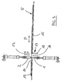
- the device according to the invention shown in FIG. 1 has a lower alignment bar 1 and an upper alignment bar 2.
- the two straightening strips 1, 2 are left with a gap 3 arranged opposite each other.
- the top straightening bar 2 has a series of in the longitudinal direction of the straightening bar 2 juxtaposed straightening elements 4, which in the 1 are only indicated schematically.
- These straightening elements 4 extend along the straightening bar 2 essentially over a length that the width of a fabric 5, between the straightening elements 4 and the lower Guideline 1 is carried out.
- the fabric 5 is in the illustration of FIG. 1 with its lower surface on the lower alignment bar 1.
- the straightening elements 4 come with its contact surface 6 on the surface of the fabric web 5 to the facility.
- FIG. 1 the detail or the section X shown in FIG. 1.
- this illustration shows the directional elements 4 each have a shaft 7 and a straightening head 8 on the lower one Straightening bar 1 pointing end of the shaft 7.
- everyone Shank 7 of each element 4 is in one in the upper alignment bar 2 arranged recess 9 arranged, these Recess downwards, i.e. to the lower alignment bar 1, and is open to the top.
- the shaft 7 of the straightening elements 4 is cylindrical, as is the recess 9.
- the diameter of the Recess 9 is slightly larger than the diameter of the cylindrical shaft 7, so that the shaft 7 in each assigned recess 9 of the upper alignment bar 2 with little radial play in the axial direction, based on the Shaft 7, is freely movable.
- the length L of the shaft 7 of the straightening elements 4 is in the the embodiment shown larger than that Height h of the upper straightening bar 2.
- the shaft 7 of each straightening element 4 is at its upper from the recess 9 of the upper Straightening bar 2 protruding end with a securing element 10 provided in the form of a circlip, on the one hand when lifting the upper guide bar 2 in the direction of the arrow F causes the respective straightening elements to be carried along and to another a falling out of the directional elements 4 from the upper Straightening bar 2 prevented.
- the Straightening foot 8 of the straightening element 4 is cuboid and has a lower contact surface 6 for flat contact with the Material web 5 and (see illustration according to FIG. 4) a straightening surface 12 for contact with the raised pile area 13 of the fabric 5 when aligning.
- the leveling surface 12 is down limited by a straightening edge 11.
- the leveling surface 12 in this embodiment of the present invention not wedge-shaped, whereby there is a risk of undesired hooking into the Reduced pile of terry cloth.
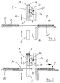
- FIG. 3 the device according to Figures 1 and 2 is in shown from the side.
- the fabric web 5 on a table 15 in the direction of the arrow P transported.
- the fabric 5 consists of alternating areas of different thickness, namely areas with a relatively thick pile 13 and flowerless streets 14.
- the fabric web 5 after positioning and alignment by the device according to the invention each in the area of a florid alley 14 by means of a cutting or separating device 17 cut.
- This Cutting device 17 consists essentially of a fixed Lower knife 18 and a complementary movable Upper knife 19.
- Both the cutting and separating device 17 as well as the device according to the invention are in the range a recess 16 of the table 15 arranged so that in this area both the upper and lower straightening strips 1, 2 as well as the upper and lower knife 18, 19 freely on the fabric 5 can reach.
- the width of the recess 16 corresponds essentially the width of the fabric web 5.
- an inventive Device both the lower straightening bar 1 and also the upper straightening bar 2, each with a device for Guidance and positioning of the respective straightening bar 1, 2 Mistake.
- This device is in the embodiment shown here from one pneumatic cylinder 20 each axial end of the straightening strips 1, 2, whereby both the lower Straightening bar 1 and the top straightening bar 2 against each other are employable or detachable from each other. Thereby at Lifting off the upper straightening bar 2 as described above the straightening elements 4 are also lifted over the securing elements 10, so that there is a wide open gap for performing the Fabric 5 or for maintenance work on the device results.
- Figures 4 to 7 is an enlarged side view Representation a section of the invention Device shown in the region of the recess 16 of the table 15.
- 4 shows a so-called open position, in which the lower straightening bar 1 is in its lowest position and the upper straightening bar 2 in its uppermost position are located. In this open position, the transport can continue fabric 5 from one florid alley 14 to the next occur. In this position, the example is shown Straightening element 4 against by a locking ring 10 Falling out of the upper alignment bar 2 secured.
- the clamping device 21 has a substantially the entire Length of the straightening bar 2 extending channel 22, wherein this channel is essentially airtight and Compressed air can be applied via a valve 23 (see FIG. 1) is.
- the channel 22 is in the embodiment shown here one over the entire axial length of the straightening bar 2 continuous strip-shaped clamping element 24 arranged, for example from a rubber-elastic material stands.
- the depth d of the channel 22 is chosen so that the shafts 7 of the straightening elements 4 at least slightly in protrude into this channel.
- the channel is over the valve 23 pressurized with compressed air, the clamping element 24 is against the shafts 7 of the straightening elements 4 are pressed and fixed in axial direction.
- To release the clamp channel 22, for example also via the valve device 23, vented.
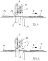
- FIG. 7 shows the use of the device according to the invention shown in a fabric 5, in which the floreless fabric is graded in the alley area 14.
- the device according to the Invention as shown in Figure 5 brought into position become.
- the clamped upper one Straightening bar only increased by the amount of step height x
- the cross-sectional profile shown by the straightening elements 4 the fabric 5 remains unchanged and the upper guide bar 2 after reaching a position that short just before the final alignment position without having to readjust the fabric profile becomes necessary.
- undesired positioning the fabric at the edge of the step in the floreless Alley 14 avoided.
Landscapes
- Engineering & Computer Science (AREA)
- Textile Engineering (AREA)
- Treatment Of Fiber Materials (AREA)
Claims (8)
- Dispositif pour aligner des pans d'étoffe qui présentent, alternant dans la direction longitudinale, des sections d'épaisseurs différentes, notamment d'étoffe d'éponge avec des bandes sans poils qui s'étendent transversalement par rapport à la direction longitudinale, dispositif qui comporte des barrettes d'alignement supérieure et inférieure (1,2) qui sont agencées sensiblement transversalement par rapport au pan d'étoffe et opposées à une faible distance l'une de l'autre, la barrette d'alignement supérieure (2) présentant une rangée d'éléments d'alignement (4) disposés dans la direction longitudinale de la barrette d'alignement, éléments d'alignement qui sont disposés dans la barrette d'alignement supérieure (2) sensiblement librement mobiles et sensiblement perpendiculairement par rapport au plan du pan d'étoffe, et qui peuvent être amenés en contact sur la barrette d'alignement inférieure (1) sous l'effet de la gravitation et avec interposition du pan d'étoffe à aligner, les éléments d'alignement (4) pouvant être fixés de façon amovible, dans la barrette d'alignement supérieure par frottement à la façon d'un serrage, après être mis sur le pan d'étoffe,
caractérisé par
au moins un conduit (22) s'étendant sensiblement sur toute la longueur de la barrette d'alignement supérieure (2), conduit qui peut être mis pneumatiquement sous pression et qui présente des ouvertures vers des évidements de guidage (9) des éléments d'alignement (4) et au moins un élément de serrage (24) pouvant être actionné pneumatiquement qui peut être mis en contact contre des tiges de guidage (7) des éléments d'alignement (4), par les ouvertures. - Dispositif selon la revendication 1,
caractérisé en ce que
les éléments d'alignement (4) présentent chacun une tige (7) qui est guidée, avec au moins un faible jeu, dans un évidement (9) de forme complémentaire de la barrette d'alignement supérieure (2), et un pied d'alignement (8) qui peut être mis en contact sur le pan d'étoffe (5). - Dispositif selon la revendication 2,
caractérisé en ce que
la tige (7) est en forme sensiblement cylindrique et présente un diamètre qui est au moins un peu inférieur à l'évidement (9) également cylindrique de la barrette d'alignement supérieure (2). - Dispositif selon la revendication 2 ou 3,
caractérisé en ce que
la longueur (L) de la tige (7) des éléments d'alignement (4) est plus grande que la hauteur (h) de la barrette d'alignement (2), l'évidement (9) traverse complètement la barrette d'alignement supérieure, et la tige (7) est retenue contre un échappement par un élément de sûreté (10) disposé sur l'extrémité supérieure de la tige qui fait saillie de la barrette d'alignement supérieure (2). - Dispositif selon l'une quelconque des revendications 2 à 4,
caractérisé en ce que
le pied d'alignement (8) de l'élément d'alignement (4) présente une surface d'appui (6) pour le contact sur le pan d'étoffe (5) et une arête d'alignement (11) et/ou une surface d'alignement (12) pour le contact contre une section à épaisseur plus élevée (13), notamment le commencement de la section à poils en cas d'étoffe d'éponge. - Dispositif selon la revendication 1,
caractérisé en ce que
l'élément de serrage (24) est un tuyau flexible sensiblement étanche à l'air qui est disposé dans le conduit (22) sur toute la longueur de ce dernier et qui peut être mis réversiblement sous pression par une vanne (23). - Dispositif selon l'une des revendications 1 à 6,
caractérisé par
des moyens de guidage et de positionnement de la barrette d'alignement inférieure et/ou supérieure (2) par rapport au plan du pan d'étoffe. - Dispositif selon la revendication 7,
caractérisé en ce que
les moyens de guidage et de positionnement sont constitués par des guidages linéaires pouvant être actionnés hydrauliquement ou pneumatiquement, notamment par des vérins pneumatiques (20), qui sont disposés aux deux extrémités axiales de la barrette de guidage supérieure (2) et/ou inférieure (1).
Applications Claiming Priority (2)
| Application Number | Priority Date | Filing Date | Title |
|---|---|---|---|
| DE4418241 | 1994-05-25 | ||
| DE19944418241 DE4418241A1 (de) | 1994-05-25 | 1994-05-25 | Vorrichtung zum Ausrichten von Stoffbahnen |
Publications (3)
| Publication Number | Publication Date |
|---|---|
| EP0684336A2 EP0684336A2 (fr) | 1995-11-29 |
| EP0684336A3 EP0684336A3 (fr) | 1995-12-27 |
| EP0684336B1 true EP0684336B1 (fr) | 2000-06-28 |
Family
ID=6518932
Family Applications (1)
| Application Number | Title | Priority Date | Filing Date |
|---|---|---|---|
| EP19950103959 Expired - Lifetime EP0684336B1 (fr) | 1994-05-25 | 1995-03-17 | Dispositif pour aligner des bandes |
Country Status (3)
| Country | Link |
|---|---|
| US (1) | US5605266A (fr) |
| EP (1) | EP0684336B1 (fr) |
| DE (2) | DE4418241A1 (fr) |
Families Citing this family (2)
| Publication number | Priority date | Publication date | Assignee | Title |
|---|---|---|---|---|
| DE29621736U1 (de) * | 1996-12-14 | 1997-02-06 | Carl Schmale GmbH & Co KG, 48607 Ochtrup | Spannleiste |
| CN110451315A (zh) * | 2019-02-14 | 2019-11-15 | 泰兴市双羊机械工程有限公司 | 一种胎面胶分切机衡张力稳压保距控制系统 |
Family Cites Families (6)
| Publication number | Priority date | Publication date | Assignee | Title |
|---|---|---|---|---|
| DE2544410C3 (de) * | 1975-10-03 | 1979-11-29 | Texpa-Arbter Maschinenbaugesellschaft Mbh, 8741 Saal | Einrichtung zum Ausrichten und fadengeraden Trennen von Stoffbahnen |
| DE3431210C2 (de) * | 1983-09-24 | 1986-02-27 | Carl Schmale GmbH & Co KG, 4434 Ochtrup | Spannleiste für Textilbahn-Ausrichtvorrichtungen, insbesondere für eine Querschneidevorrichtung |
| US4595133A (en) * | 1984-06-18 | 1986-06-17 | Opelika Manufacturing Corporation | Towel aligning, cutting and hemming system |
| US4771928A (en) * | 1986-05-09 | 1988-09-20 | Takanori Okada | Towel fabric processing device |
| SE467259B (sv) * | 1987-10-09 | 1992-06-22 | Akab Of Sweden Ab | Anordning foer riktning av avskaerning av en tygbana |
| JPH0226984A (ja) * | 1988-07-11 | 1990-01-29 | Singer Nikko Kk | タオル生地の裁断装置 |
-
1994
- 1994-05-25 DE DE19944418241 patent/DE4418241A1/de not_active Ceased
-
1995
- 1995-03-17 DE DE59508505T patent/DE59508505D1/de not_active Expired - Lifetime
- 1995-03-17 EP EP19950103959 patent/EP0684336B1/fr not_active Expired - Lifetime
- 1995-05-16 US US08/441,815 patent/US5605266A/en not_active Expired - Lifetime
Also Published As
| Publication number | Publication date |
|---|---|
| US5605266A (en) | 1997-02-25 |
| EP0684336A2 (fr) | 1995-11-29 |
| DE59508505D1 (de) | 2000-08-03 |
| DE4418241A1 (de) | 1995-11-30 |
| EP0684336A3 (fr) | 1995-12-27 |
Similar Documents
| Publication | Publication Date | Title |
|---|---|---|
| EP1867448B1 (fr) | Appareil a couper de la feuille en rouleau | |
| DE2759966C3 (de) | Schalung | |
| DE1142574B (de) | Vorrichtung zum Herstellen von Verpackungsbehaeltern | |
| DE2404840C3 (de) | Verfahren zur Trennung von in einem Bogen zusammenhängenden Nutzenabschnitten und Vorrichtung zur Durchführung des Verfahrens | |
| DE2245215B2 (de) | Fadenleiter | |
| EP0684336B1 (fr) | Dispositif pour aligner des bandes | |
| CH652336A5 (de) | Stanzmaschine. | |
| EP0518217A1 (fr) | Presse pour bois à lames pour la fabrication de poutres fermes collées et arguées | |
| DE2907711C2 (de) | Vorrichtung zum Schneiden von Profilen aus einem Materialblock | |
| DE2152531C3 (de) | Rahmenpresse für Holzrahmen, insbesondere für Fensterrahmen | |
| DE2502866C2 (de) | Vorrichtung und Verfahren zum Schneiden eines noch plastischen Porenbetonblockes | |
| DE1018841B (de) | Lochstanze, insbesondere zum Lochen von Papierlagen | |
| DE8417560U1 (de) | Parallelhobelmaschine | |
| DE2541452A1 (de) | Maschine zum verbinden von holzleisten | |
| DE29617447U1 (de) | Bohrtisch | |
| DE3632123C2 (de) | Biegepresse | |
| DE19810574B4 (de) | Vorrichtung zur Betätigung von Pressen in Klemmeinrichtungen für den Zusammenbau von Möbelstücken | |
| DE3608113C2 (fr) | ||
| DE3431210A1 (de) | Spannleiste fuer textilbahn-ausrichtvorrichtungen, insbesondere fuer eine querschneidevorrichtung | |
| DE9320608U1 (de) | Vorrichtung zur Verlegung eines Fertigparkett- oder Laminarfußbodens | |
| DE1045076B (de) | Maschine zur Herstellung von Platten, insbesondere Mittellagen | |
| DE102004052549B4 (de) | Abstandhalter für den Betonbau sowie Vorrichtung zum Aufbringen mehrerer Abstandhalter auf einen Bewehrungsstab | |
| DE135786C (fr) | ||
| DE4134414A1 (de) | Vorrichtung zum nietartigen verbinden von blechartigen teilen | |
| DE3417097A1 (de) | Verfahren und geraet zum stapeln und verpacken von langware in einem saegewerk, insbesondere zum stapeln und verpacken von dachlatten o.ae. |
Legal Events
| Date | Code | Title | Description |
|---|---|---|---|
| PUAI | Public reference made under article 153(3) epc to a published international application that has entered the european phase |
Free format text: ORIGINAL CODE: 0009012 |
|
| PUAL | Search report despatched |
Free format text: ORIGINAL CODE: 0009013 |
|
| AK | Designated contracting states |
Kind code of ref document: A2 Designated state(s): DE IT SE |
|
| AK | Designated contracting states |
Kind code of ref document: A3 Designated state(s): DE IT SE |
|
| 17P | Request for examination filed |
Effective date: 19951201 |
|
| 17Q | First examination report despatched |
Effective date: 19980205 |
|
| RAP1 | Party data changed (applicant data changed or rights of an application transferred) |
Owner name: TEXPA MASCHINENBAU GMBH & CO. KG |
|
| GRAG | Despatch of communication of intention to grant |
Free format text: ORIGINAL CODE: EPIDOS AGRA |
|
| GRAG | Despatch of communication of intention to grant |
Free format text: ORIGINAL CODE: EPIDOS AGRA |
|
| GRAH | Despatch of communication of intention to grant a patent |
Free format text: ORIGINAL CODE: EPIDOS IGRA |
|
| GRAH | Despatch of communication of intention to grant a patent |
Free format text: ORIGINAL CODE: EPIDOS IGRA |
|
| ITF | It: translation for a ep patent filed | ||
| GRAA | (expected) grant |
Free format text: ORIGINAL CODE: 0009210 |
|
| AK | Designated contracting states |
Kind code of ref document: B1 Designated state(s): DE IT SE |
|
| REF | Corresponds to: |
Ref document number: 59508505 Country of ref document: DE Date of ref document: 20000803 |
|
| EN | Fr: translation not filed | ||
| PLBE | No opposition filed within time limit |
Free format text: ORIGINAL CODE: 0009261 |
|
| STAA | Information on the status of an ep patent application or granted ep patent |
Free format text: STATUS: NO OPPOSITION FILED WITHIN TIME LIMIT |
|
| 26N | No opposition filed | ||
| PGFP | Annual fee paid to national office [announced via postgrant information from national office to epo] |
Ref country code: SE Payment date: 20080320 Year of fee payment: 14 |
|
| EUG | Se: european patent has lapsed | ||
| PGFP | Annual fee paid to national office [announced via postgrant information from national office to epo] |
Ref country code: IT Payment date: 20100325 Year of fee payment: 16 |
|
| PGFP | Annual fee paid to national office [announced via postgrant information from national office to epo] |
Ref country code: DE Payment date: 20100519 Year of fee payment: 16 |
|
| PG25 | Lapsed in a contracting state [announced via postgrant information from national office to epo] |
Ref country code: SE Free format text: LAPSE BECAUSE OF NON-PAYMENT OF DUE FEES Effective date: 20090318 |
|
| PG25 | Lapsed in a contracting state [announced via postgrant information from national office to epo] |
Ref country code: DE Free format text: LAPSE BECAUSE OF NON-PAYMENT OF DUE FEES Effective date: 20111001 |
|
| REG | Reference to a national code |
Ref country code: DE Ref legal event code: R119 Ref document number: 59508505 Country of ref document: DE Effective date: 20111001 |
|
| PG25 | Lapsed in a contracting state [announced via postgrant information from national office to epo] |
Ref country code: IT Free format text: LAPSE BECAUSE OF NON-PAYMENT OF DUE FEES Effective date: 20110317 |