EP0684331B1 - Verfahren zum Steuern vom horizontalen Versatz der Hülsentragbarren in Beziehung mit vorher bestimmten Distanzen zwischen den Nadelmitten an Strickmaschinen - Google Patents
Verfahren zum Steuern vom horizontalen Versatz der Hülsentragbarren in Beziehung mit vorher bestimmten Distanzen zwischen den Nadelmitten an Strickmaschinen Download PDFInfo
- Publication number
- EP0684331B1 EP0684331B1 EP94830247A EP94830247A EP0684331B1 EP 0684331 B1 EP0684331 B1 EP 0684331B1 EP 94830247 A EP94830247 A EP 94830247A EP 94830247 A EP94830247 A EP 94830247A EP 0684331 B1 EP0684331 B1 EP 0684331B1
- Authority
- EP
- European Patent Office
- Prior art keywords
- steps
- process according
- yarn carrier
- values
- stepping motor
- Prior art date
- Legal status (The legal status is an assumption and is not a legal conclusion. Google has not performed a legal analysis and makes no representation as to the accuracy of the status listed.)
- Expired - Lifetime
Links
- 238000009940 knitting Methods 0.000 title claims description 43
- 230000033001 locomotion Effects 0.000 title claims description 30
- 238000000034 method Methods 0.000 title claims description 27
- 230000008569 process Effects 0.000 title claims description 23
- 230000002596 correlated effect Effects 0.000 title claims description 9
- 230000001276 controlling effect Effects 0.000 title claims description 6
- 230000000875 corresponding effect Effects 0.000 claims description 16
- 230000001133 acceleration Effects 0.000 claims description 7
- 238000001514 detection method Methods 0.000 claims description 7
- 239000003990 capacitor Substances 0.000 claims description 3
- 230000001419 dependent effect Effects 0.000 claims description 3
- 238000013439 planning Methods 0.000 claims description 3
- 238000003780 insertion Methods 0.000 claims description 2
- 230000037431 insertion Effects 0.000 claims description 2
- 101100521334 Mus musculus Prom1 gene Proteins 0.000 claims 1
- 230000003287 optical effect Effects 0.000 description 7
- 230000015654 memory Effects 0.000 description 6
- 238000006073 displacement reaction Methods 0.000 description 4
- 230000007246 mechanism Effects 0.000 description 4
- 230000003534 oscillatory effect Effects 0.000 description 4
- 230000000903 blocking effect Effects 0.000 description 3
- 230000015572 biosynthetic process Effects 0.000 description 2
- 230000006870 function Effects 0.000 description 2
- 230000003245 working effect Effects 0.000 description 2
- 230000009471 action Effects 0.000 description 1
- 238000004146 energy storage Methods 0.000 description 1
- 230000001771 impaired effect Effects 0.000 description 1
- 238000007726 management method Methods 0.000 description 1
- 238000004519 manufacturing process Methods 0.000 description 1
- 238000012986 modification Methods 0.000 description 1
- 230000004048 modification Effects 0.000 description 1
- 238000012544 monitoring process Methods 0.000 description 1
- 238000012545 processing Methods 0.000 description 1
- 230000000750 progressive effect Effects 0.000 description 1
- 239000000126 substance Substances 0.000 description 1
- 230000001360 synchronised effect Effects 0.000 description 1
- 238000012360 testing method Methods 0.000 description 1
- 238000012384 transportation and delivery Methods 0.000 description 1
Images
Classifications
-
- D—TEXTILES; PAPER
- D04—BRAIDING; LACE-MAKING; KNITTING; TRIMMINGS; NON-WOVEN FABRICS
- D04B—KNITTING
- D04B27/00—Details of, or auxiliary devices incorporated in, warp knitting machines, restricted to machines of this kind
- D04B27/10—Devices for supplying, feeding, or guiding threads to needles
- D04B27/24—Thread guide bar assemblies
- D04B27/26—Shogging devices therefor
Definitions
- the present invention relates to a process for controlling the horizontal movements of yarn carrier bars, correlated with a predetermined distance between centres of the knitting needles in knitting machines comprising the features recited in the preamble of claim 1.
- the threading tubes are arranged in one or more rows disposed parallelly in side by side relation, each of which is supported by a corresponding yarn carrier bar through which the necessary reciprocating motions are transmitted so that the threading tubes may describe, by turns at each work stroke, a given trajectory selectively extending astride of one or more needles.
- the yarn carrier bars are engaged, at the respective opposite ends, to a pair of lifting plates simultaneously driven in an oscillatory motion by a vertical-movement mechanical linkage.
- operating on each of the yarn carrier bars is a second mechanical linkage giving the bar itself, and therefore the corresponding threading tubes, a horizontal oscillatory movement which, in combination with the above mentioned vertical movement, makes the threading tubes describe displacements according to a curved trajectory astride of the needles.
- the reciprocating movement of the individual yarn carrier bars is achieved with the aid of the so-called "Glieder chains", consisting each of a plurality of suitably shaped cam elements, interlinked one after the other in an endless line.
- the cam elements of the individual Glieder chains mounted on appropriate driving pulleys set in rotation, act on respective cam followers associated with the individual yarn carrier bars in order to cause the horizontal movement of the latter according to a width each time proportional to the lifting of the cam element coming into engagement with the cam follower.
- the angular position of the main shaft and of the guide bar is determined by two absolute transmitters, each of which can provide a different signal value for each angular position of the main shaft and for each guide bar position.
- a continous displacement function is developed for the guide bar. Such a function relates each measured angular position of the main shaft with a position target value for the guide bar.
- a position control circuit controls a setting electrical linear motor that displaces the guide bar, avoiding dangerous collisions between the elements of the guide bars and other working parts of the machine.
- the Applicant has recently developed a device that, in place of said Glieder chains, utilizes a plurality of electric stepping motors operatively connected each with one of the yarn carrier bars.
- the selective operation of the stepping motors is managed by a programmable electronic control box into which any programs relating to the management of the motors themselves can be easily loaded, according to a work cycle suitable to obtain the desired pattern or embroidery in the manufactured article produced by the machine.
- the program loaded into the electronic control box contains all information relating to the extent of the stroke to be carried out, upon command of the respective motor, by each of the yarn carrier bars, at each knitting step.
- a plate-like element is arranged on the output shaft of each of the stepping motors, which plate-like element is provided with optical references spaced apart from each other an amount corresponding to the distance between centres of the needles.
- Optical detectors interlocked to the control box and combined with each of the motors detect when the optical reference passes a predetermined reading point. Therefore the control box itself is capable of evaluating the number of needles ridden over by the threading tubes as a result of the movements of each yarn carrier bar so as to stop the horizontal movement of said bar at the appropriate moment.
- Each stepping motor is also equipped with a blocking mechanism adapted to intervene whenever the power supply to the knitting machine is broken, in order to ensure that the corresponding yarn carrier bar is stopped at a position adapted to enable the threading tubes to be inserted between the needles in the absence of mechanical interferences during the vertical strokes that are unavoidably carried out by the yarn carrier bars under inertia, before the knitting machine thoroughly stops.
- Each of these blocking mechanisms consists of a sector gear connected to the output shaft of the corresponding motor. This sector gear, the teeth of which are spaced apart an amount corresponding to the distance between centres of the needles, is designed to be engaged by a fitting wedge that, during the usual operation of the machine, is held by an electromagnet couteracting the elastic action of a spring.
- the resulting de-energizing of the electromagnet causes the engagement of the fitting wedge between two consecutive teeth of the sector gear and, as a result, locking of the yarn carrier bar at a position adapted to avoid mechanical interferences between the threading tubes and the needles.
- the electronic control box is exclusively capable of carrying out counting of the optical references passing before the reading points and does not have the possibility of executing any precise monitoring as regards the actual position of the yarn carrier bars in relation to the angular positioning of the output shafts of the stepping motors.
- an optical reference stopping at the reading point may slightly move back and, subsequently, reach again the reading point.
- the electronic control box would interpret such a circumstance as a displacement of the yarn carrier bar by an amount equal to the distance between centres of the needles whereas, as a matter of fact, the bar has not substantially moved.
- sector gears of the above mentioned blocking mechanisms must be replaced each time the working fineness is changed and, in addition, apart from that, the presence of said sector gears makes the device as a whole much more complicated.
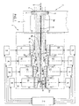
- FIG. 1 is a diagrammatic view of a portion of a knitting machine equipped with stepping motors governed by a central control unit and each of which is associated with a respective microprocessor unit provided with a control firmware in accordance with the present invention.
- a device for the horizontal movement of yarn carrier bars in a knitting machine has been generally identified by reference numeral 1.
- the device 1 is associated with a knitting machine, and more particularly a crochet galloon loom 2 and is arranged to act on one or more yarn carrier bars 3 (only one of which is shown) to cause the reciprocating motion of same.
- the yarn carrier bars 3 in known manner, carry a plurality of threading tubes, not shown, engaging respective weft yarns, not shown, and are operatively supported by at least two lifting plates 4 (only one of which is shown) slidably engaging said bars 3 according to a horizontal direction coinciding with the longitudinal extension of the yarn carrier bars themselves.
- Each lifting plate 4 is slidably guided in a vertical direction on a pair of guide rods 5 integral with a bed 6 of the knitting machine and the plates are simultaneously operated in a reciprocating motion along the rods by a mechanical linkage consisting of a connecting rod-crank assembly housed in the machine bed and not shown as known per se and conventional.
- composition of the vertical oscillatory motion and horizontal oscillatory motion imparted to each yarn carrier bar 3, through the device 1, is such that the engaged threading tubes are driven in a reciprocating motion according to a substantially curved trajectory extending astride of one or more knitting needles (not shown in the drawing).
- the device 1 provides for the presence of a plurality of driving rods 8, each of which has one end 8a operatively linked to the end of one of the bars 3, as well as a second end 8b connected to an electric stepping motor 10 fastened, by a supporting bracket 10a, to a bearing framework 11 integral with the machine bed 6.
- Each stepping motor 10 known per se and conventional, lends itself to drive in rotation a respective output shaft 12 according to angular steps in succession having each a given angular width.
- each stepping motor 10 is operatively connected to one of the driving rods 8 by an intermediate mechanical linkage 13 designed to transmit the horizontal movements to the corresponding yarn carrier bar 3 following the angular rotation imparted to the drive shaft itself.
- Such an intermediate linkage 13 preferably consists of a crank 14 keyed onto the output shaft 12 and operatively engaged to a connecting rod 15 connected to the driving rod 8.
- each connecting rod 15 and the respective driving rod 8 is achieved by means of a linking element in the form of a rod 16 slidably guided in a horizontal direction parallel to the movement of the yarn carrier bars 3 on a guide support 17 fastened to the framework 11.
- denoted by 9 is a plurality of microprocessor units interfacing in circuit with a central control unit 7, equipped with a microprocessor of the NEC 78K family and provided with an external key-operated control panel, not shown in the figure.
- the microprocessor units 9, assembled on each motor 10 coaxially with the output shaft 12 on the opposite side from the intermediate linkage 13, are cards provided with a microprocessor of the NEC 75X family having their own electrically programmable read only memories (EPROMs) and electrically erasable programmable read only memories (EEPROMs) associated in circuit, through connectors, to an absolute encoder carrying out the detection of the positioning steps of the respective stepping motor and sending a 10-bit signal (according to the known Gray code used in absolute encoders) to the respective microprocessor unit 9.
- EPROMs electrically programmable read only memories
- EEPROMs electrically erasable programmable read only memories
- Each of said microprocessor units is also equipped with the whole interfacing circuitry, through a 485 serial line, with the central control unit 7 and, through optoisolators, with the respective stepping motor 10.
- capacitors are also provided in the power circuitry, that are charged during normal operation thereby giving rise to an energy storage which is available for use.
- each microprocessor unit 9 carries out the detection of the angular position of the output shaft 12 of each stepping motor 10 with which it is associated.
- each of the yarn carrier bar of each knitting machine is brought to a predetermined position, for identifying the reference zero of each motor 10 through detection, by the respective encoder, of the angular position correspondingly taken by the output shaft.
- each motor 10 will be a given angle representing the respective reference zero.
- This reference zero is then sent, in the form of a signal relating to positioning, to the respective microprocessor unit 9 that will interpret it and store it into its own EEPROM.
- Both the microprocessor units 9 and central control unit 7 are respectively provided with a control firmware, developed in assembler language, in which reference tables of coded parameters have been logically scheduled, such as: operating speed of the knitting machine, number of angular steps that each motor must correspondingly carry out at each stroke of the yarn carrier bars, value of the distance between centres of the needles (stitch gauge), angular speed, acceleration, deceleration to be imparted to the output shafts of the individual stepping motors, as well as tolerance values and implementation procedures relating to the arranged working cycles.
- a control firmware developed in assembler language, in which reference tables of coded parameters have been logically scheduled, such as: operating speed of the knitting machine, number of angular steps that each motor must correspondingly carry out at each stroke of the yarn carrier bars, value of the distance between centres of the needles (stitch gauge), angular speed, acceleration, deceleration to be imparted to the output shafts of the individual stepping motors, as well as tolerance values and implementation procedures
- a remote unit not shown in the drawing, is also provided and it consists of a personal computer, into which the working cycles designed to be then transferred to unit 7 have been preloaded in the form of Quick-Basic-developed programs.
- This transferring is carried out, in connection with the embodiment being described, by an infrared beam system providing for the use of a remote control means that draws the desired working cycles from the personal computer by means of an RS 232 serial line, stores them into random access memories (RAM) provided with a buffer storage and enables them to be transferred to unit 7 through an infrared sensor, provided in said unit 7.
- a remote control means that draws the desired working cycles from the personal computer by means of an RS 232 serial line, stores them into random access memories (RAM) provided with a buffer storage and enables them to be transferred to unit 7 through an infrared sensor, provided in said unit 7.
- RAM random access memories
- each microprocessor unit 9 is of the absolute type, enables a 360° counting, and enables a univocal identification, through the known 10-bit Gray code, of the positioning of the output shaft 12 of each stepping motor 10 which, in connection with the embodiment being described, carries out a complete revolution (360°) in 800 steps.
- the machine is started and thus all stepping motors 10 are brought to the respective first work position which can coincide with anyone of the angular positions detected by the respective absolute encoder, in connection with the established stitch gauge.
- each stepping motor 10 will have its own zero, defined by a certain angular degree detected by the absolute encoder and corresponding to a mechanical zero which is the same for all of them.
- EEPROM Integrated in the EEPROM of each microprocessor unit 9 and sent from the central control unit 7 is a series of tolerance values of angular positioning within which each stepping motor must stop its output shaft at the end of each stroke imparted to the corresponding yarn carrier bar.
- tolerance values in the form of numerical values referring to the tolerance margins of said angular positionings and processed on the basis of a corresponding algorithm of the control firmware, enable a continuous control of the steps that each motor 10 must carry out in order to move the respective output shaft 12 without exceeding, at the end of each stroke, the margins previously entered during the planning stage.
- boundary parameters can be defined, such as the operating speed of the knitting machine, the number of the angular steps that each motor 10 must execute, in observance of the selected working cycle, correspondingly with each stroke of the yarn carrier bar, as well as the stitch gauge value.
- boundary parameters are scheduled into parametric reference tables, logically correlated with each other, within said control firmware, based on a corresponding algorithm.
- Also provided by the process is the programming and mutual comparison of the angular speed, acceleration and decelaration values to be given to the output shafts of the individual stepping motors depending on said boundary parameters, in order to establish, at each moment of the selected working cycle, a single resulting positioning value of the respective motor 10 so that, at the end of the yarn carrier bar stroke, the insertion of the threading tubes between the knitting needles be ensure in the observance of the tolerance margins defined in the planning stage.
- the foregoing aims at achieving an actual and efficient control of the knitting machine without involving too important mechanical stresses and interferences between the threading tubes and knitting needles.
- the above process is embodied by a plurality of procedures of a control programm stored in the form of a firmware into memories of the central control unit 7 and microprocessor unit 9.
- each stepping motor 10 supplied with the energy stored in the above capacitors, can residually stop and carry out a minimum number of steps, so that the corresponding yarn carrier bar is stopped when the respective threading tubes are in alignment with the spaces defined between the consecutive knitting needles.
- a procedure for stopping each stepping motor is automatically activated, after execution of a residual number of steps, at an angular speed, at an acceleration and/or deceleration that are exclusively dependent on the values of the boundary paramaters at the moment.
- program selections that in addition enable numbering of the axes, which means giving each axis a progressive numbering.
- the invention attains the intended purposes.
Landscapes
- Engineering & Computer Science (AREA)
- Textile Engineering (AREA)
- Knitting Machines (AREA)
Claims (14)
- Verfahren zum Steuern vom horiziontalen Versatz der Hülsentragbarren (3) in Beziehung mit vorher bestimmten Distanzen zwischen den Nadelmitten an Strickmaschinen, verbunden mit der Verwendung von einer Vielzahl von Motoren (10), die wirksam jeweils mit einem Hülsentragbarren (3) verbunden sind, um diesen letzteren Hin- und Herbewegungen mit änderbaren Hubweiten zu übertragen, sowie mit einer zentralen Überwachungseinheit (7), um die durch diese Motoren (10) ausgeführten Arbeitsabläufe zu steuern, wobei dieses Verfahren die folgenden an einer Prozessoreinheit (9) ausgeführten Programmierungsschritte umfaßt, die mit der zentralen Überwachungseinheit (7) zusammenwirken, mit dem Netz über eine Leistungsschaltung verbunden und jeweils einem der Motore zugeordnet sind:dadurch gekennzeichnet, daß die Motoren (10) Schrittmotoren sind und dadurch, daß der Schritt zur Festlegung einer Randparameterreihe mit deren Organisation in Parametertabellen verbunden ist, die die Betriebsgeschwindigkeit der Strickmaschine, die Anzahl der Winkelschritte, die jeder Motor entsprechend einen jeden Hubes des Hülsentragbarrens (3) ausführen muß, sowie den Distanzwert zwischen den Nadeln bestimmen.a) Auflistung einer Reihe von Positionierungstoleranzwerten, innerhalb denen jeder Motor (10) die eigene Abtriebswelle (12) am Ende eines jeden, dem jeweiligen Hülsentragbarren (3) erteilten Hub anhalten muß;b) Festlegung einer Randparameterreihe;c) Programmierung der Drehzahl-, Beschleunigungs- und Verzögerungswerte, die den Abtriebswellen (12) der einzelnen Motoren (10) in Abhängigkeit der Randparameter zu erteilen sind,
- Verfahren nach Anspruch 1, dadurch gekennzeichnet, daß beim Schritt a) eine Vielzahl von Zahlenwerten bereitgestellt sind, die sich auf die Toleranzspannen von Winkelpositionierungen beziehen, miteinander logisch organisiert und in Korrelation derart gebracht sind, daß in Beachtung des ausgewählten Bearbeitungsablaufes, der Antrieb der Abtriebswelle (12) eines jeden Schrittmotors (10) gemäß einer Anzahl von Schritten festgelegt wird, die nicht die genannten konstruktiv festgelegten Spannen überschreitet.
- Verfahren nach Anspruch 1, dadurch gekennzeichnet, daß die Schritte b) und c) vorsehen, die Randparameter miteinander logisch derart in Korrelation zu bringen, daß sie den Drehzahl-, Beschleunigungs- und Verzögerungswerten der Abtriebswelle (12) eines jeden Schrittmotors (10) zugeordnet werden, um eine Positionierung der Welle dieses letzteren mit einer Anzahl von Schritten festzulegen, die gemäß einer Geschwindigkeit, einer Beschleunigung und einer Verzögerung festgelegt ist, die sich aus einem Vergleichsprozeß zwischen den erwähnten Werten ergeben und von Mal zu Mal von den Randparametern an diesem Zeitpunkt abhängen.
- Verfahren nach Anspruch 3, dadurch gekennzeichnet, daß zufolge eines Ausbleibens von Stromzufuhr, ein Anhalten eines jeden Schrittmotors (10) vorgesehen wird, indem eine Restanzahl von Schritten mit einer Drehzahl, einer Beschleunigung und einer darauffolgenden Verzögerung durchgeführt wird, die ausschließlich von den Werten der Rand parameter in diesem Moment abhängen.
- Verfahren nach Anspruch 3, dadurch gekennzeichnet, daß zufolge eines Ausbleibens der Stromzufuhr, ein Anhalten eines jeden Schrittmotors (10) vorgesehen wird, nachdem eine Restanzahl von Schritten bei einer Drehzahl und einer Verzögerung durchgeführt wird, die ausschließlich von den Werten der Randparameter in diesem Moment abhängen.
- Verfahren nach Anspruch 4, dadurch gekennzeichnet, daß die Restanzahl von Schritten ein Minimum ist, damit der jeweilige Hülsentragbarren (3) entsprechende Fadenführhülsen bereitstellt, um jeweils zwischen zwei nacheinanderfolgenden Nadeln eingebracht zu werden.
- Verfahren nach Anspruch 4, dadurch gekennzeichnet, daß die Restanzahl von Schritten dadurch ausgeführt wird, indem diese Schrittmotoren (10) über gespeicherte Energie während des normalen Betriebes von Kondensatore gespeist werden, mit denen die Leistungsschaltung versehen ist.
- Verfahren nach Anspruch 1, dadurch gekennzeichnet, daß die Programmierungsschritte Programmabläufe sind, die an EPROM gespeichert sind, die an der zentralen Überwachungseinheit (7) zusammengefügt sind.
- Verfahren nach Anspruch 1, dadurch gekennzeichnet, daß die Reihe von Toleranzwerten nach Punkt a), von Randparametern nach Punkt b) sowie von Werten nach Punkt c) in einem Programm organisiert sind, das an PROM gespeichert ist, die an den Mikroprozessoreinheiten (9) der Schrittmotoren (10) zusammengefügt sind.
- Verfahren nach Anspruch 1, dadurch gekennzeichnet, daß die Erfassung der Anzahl der von jedem Schrittmotor (10) durchgeführten Schritte über einen absoluten Encoder durchgeführt wird, der jedem derselben zugeordnet ist.
- Verfahren nach Anspruch 10, dadurch gekennzeichnet, daß die Erfassung der Anzahl der von jedem Schrittmotor (10) durchgeführten Schritte über einen absoluten Encoder durchgeführt wird, der den Gray-Codex verwendet.
- Verfahren nach Anspruch 10, dadurch gekennzeichnet, daß die Erfassung der Anzahl der von jedem Schrittmotor (10) durchgeführten Schritte über einen absoluten Encoder zu zehn bit durchgeführt wird.
- Verfahren nach Anspruch 1, dadurch gekennzeichnet, daß jeder Arbeitsablauf der Strickmaschine (1) über eine Infrarotfernsteuerung erfolgt.
- Verfahren nach Anspruch 13, dadurch gekennzeichnet, daß jede Strickmaschine (1) mit einem Infrarotempfänger versehen ist, um die Bearbeitungsabläufe der Infrarotfernsteuerung zu empfangen.
Priority Applications (6)
| Application Number | Priority Date | Filing Date | Title |
|---|---|---|---|
| ES94830247T ES2123115T3 (es) | 1994-05-24 | 1994-05-24 | Procedimiento para controlar los movimientos horizontales de las barras portadoras de hilo en relacion con distancias predeterminadas entre los centros de las agujas en maquinas tricotosas. |
| EP94830247A EP0684331B1 (de) | 1994-05-24 | 1994-05-24 | Verfahren zum Steuern vom horizontalen Versatz der Hülsentragbarren in Beziehung mit vorher bestimmten Distanzen zwischen den Nadelmitten an Strickmaschinen |
| DE69413007T DE69413007T2 (de) | 1994-05-24 | 1994-05-24 | Verfahren zum Steuern vom horizontalen Versatz der Hülsentragbarren in Beziehung mit vorher bestimmten Distanzen zwischen den Nadelmitten an Strickmaschinen |
| CA002130860A CA2130860C (en) | 1994-05-24 | 1994-08-25 | Process for controlling the horizontal movements of yarn carrier bars correlated with a predetermined distance between centres of the knitting needles in knitting machines |
| US08/302,588 US5502987A (en) | 1994-05-24 | 1994-09-08 | Process for controlling the horizontal movements of yarn carrier bars correlated with a predetermined distance between centers of the knitting needles in knitting machines |
| CN94113748A CN1069936C (zh) | 1994-05-24 | 1994-11-01 | 控制涉及织针中心间的预定距离的导纱杆水平运动的方法 |
Applications Claiming Priority (1)
| Application Number | Priority Date | Filing Date | Title |
|---|---|---|---|
| EP94830247A EP0684331B1 (de) | 1994-05-24 | 1994-05-24 | Verfahren zum Steuern vom horizontalen Versatz der Hülsentragbarren in Beziehung mit vorher bestimmten Distanzen zwischen den Nadelmitten an Strickmaschinen |
Publications (2)
| Publication Number | Publication Date |
|---|---|
| EP0684331A1 EP0684331A1 (de) | 1995-11-29 |
| EP0684331B1 true EP0684331B1 (de) | 1998-09-02 |
Family
ID=8218450
Family Applications (1)
| Application Number | Title | Priority Date | Filing Date |
|---|---|---|---|
| EP94830247A Expired - Lifetime EP0684331B1 (de) | 1994-05-24 | 1994-05-24 | Verfahren zum Steuern vom horizontalen Versatz der Hülsentragbarren in Beziehung mit vorher bestimmten Distanzen zwischen den Nadelmitten an Strickmaschinen |
Country Status (6)
| Country | Link |
|---|---|
| US (1) | US5502987A (de) |
| EP (1) | EP0684331B1 (de) |
| CN (1) | CN1069936C (de) |
| CA (1) | CA2130860C (de) |
| DE (1) | DE69413007T2 (de) |
| ES (1) | ES2123115T3 (de) |
Families Citing this family (13)
| Publication number | Priority date | Publication date | Assignee | Title |
|---|---|---|---|---|
| CN1063499C (zh) * | 1995-01-19 | 2001-03-21 | 日本迈耶株式会社 | 经编机的提花装置的控制方法 |
| US5956978A (en) * | 1995-10-11 | 1999-09-28 | Textilma Ag | Knitting machine |
| TW437759U (en) * | 1997-02-26 | 2001-05-28 | Nippon Mayer Co Ltd | Guide driving device for warp knitting machines |
| ES2176943T3 (es) | 1998-12-23 | 2002-12-01 | Luigi Omodeo Zorini | Dispositivo actuador para el movimiento controlado de miembros en tricotosas. |
| GB9901358D0 (en) * | 1999-01-22 | 1999-03-10 | Griffith Textile Mach Ltd | A tuft yarn selection mechanism |
| DE10066042B4 (de) | 2000-08-23 | 2004-12-02 | Karl Mayer Textilmaschinenfabrik Gmbh | Kettenwirkmaschine mit mehreren Musterlegebarren |
| DE10041193B4 (de) * | 2000-08-23 | 2004-07-22 | Karl Mayer Textilmaschinenfabrik Gmbh | Kettenwirkmaschine mit mehreren Musterlegebarren |
| ITMI20010069A1 (it) * | 2001-01-16 | 2002-07-16 | Corrado Pedroni | Gruppo di comando per l'azionamento di telai raschel multibarre |
| DE60324801D1 (de) * | 2003-09-30 | 2009-01-02 | Luigi Omodeo Zorini | Textilmaschine und deren Steuerung |
| ATE308634T1 (de) | 2003-10-21 | 2005-11-15 | Luigi Omodeo Zorini | Steuerungsvorrichtung für textilmaschinen, insbesondere für häkelmaschinen |
| EP1932957B1 (de) | 2006-12-13 | 2013-08-21 | Liba Maschinenfabrik GmbH | Verfahren zum Anhalten einer Wirkmaschine |
| CN112448626B (zh) * | 2020-11-12 | 2022-07-05 | 浙江大华技术股份有限公司 | 云台电机参数配置方法、装置、电子装置和存储介质 |
| CN113026194B (zh) * | 2021-03-04 | 2022-06-21 | 常州市鑫辉网具有限公司 | 一种捆草网经编机梳栉运动方法和装置及捆草网经编机 |
Family Cites Families (5)
| Publication number | Priority date | Publication date | Assignee | Title |
|---|---|---|---|---|
| TW207555B (de) * | 1991-09-16 | 1993-06-11 | Zorini Luigi Omodeo | |
| DE4215798C2 (de) * | 1992-05-13 | 1994-03-24 | Mayer Textilmaschf | Kettenwirkmaschine |
| DE4215716C2 (de) * | 1992-05-13 | 1994-06-09 | Mayer Textilmaschf | Steuervorrichtung für den Legeschienenversatz bei Kettenwirkmaschinen |
| DE4215691C2 (de) * | 1992-05-13 | 1996-07-25 | Mayer Textilmaschf | Kettenwirkmaschine |
| DE4227758C2 (de) * | 1992-08-21 | 1995-02-09 | Wirkbau Textilmaschinenbau Gmb | Antriebsvorrichtung für parallel zur Nadelbarre einer Flachwirkmaschine, zwischen definierten Positionen hin- und herbewegbaren Arbeitselementen |
-
1994
- 1994-05-24 DE DE69413007T patent/DE69413007T2/de not_active Expired - Fee Related
- 1994-05-24 EP EP94830247A patent/EP0684331B1/de not_active Expired - Lifetime
- 1994-05-24 ES ES94830247T patent/ES2123115T3/es not_active Expired - Lifetime
- 1994-08-25 CA CA002130860A patent/CA2130860C/en not_active Expired - Fee Related
- 1994-09-08 US US08/302,588 patent/US5502987A/en not_active Expired - Fee Related
- 1994-11-01 CN CN94113748A patent/CN1069936C/zh not_active Expired - Fee Related
Also Published As
| Publication number | Publication date |
|---|---|
| DE69413007D1 (de) | 1998-10-08 |
| ES2123115T3 (es) | 1999-01-01 |
| US5502987A (en) | 1996-04-02 |
| DE69413007T2 (de) | 1999-01-21 |
| EP0684331A1 (de) | 1995-11-29 |
| CN1069936C (zh) | 2001-08-22 |
| CA2130860A1 (en) | 1995-11-25 |
| CN1119682A (zh) | 1996-04-03 |
| CA2130860C (en) | 2002-10-29 |
Similar Documents
| Publication | Publication Date | Title |
|---|---|---|
| EP0684331B1 (de) | Verfahren zum Steuern vom horizontalen Versatz der Hülsentragbarren in Beziehung mit vorher bestimmten Distanzen zwischen den Nadelmitten an Strickmaschinen | |
| EP0353005B1 (de) | Kontrollvorrichtung für Webmaschinen oder dergleichen | |
| CN1061399C (zh) | 经编机 | |
| EP0867553A2 (de) | Tuftingmaschine mit Präzisionsantriebssystem | |
| GB2221326A (en) | Control of tufting machines | |
| CN1827886A (zh) | 经编机电子送经系统 | |
| GB1473344A (en) | Control apparatus for a warp knitting machine | |
| EP0708190B1 (de) | Antriebsvorrichtung zur Übertragung von horizontalen hin- und hergehenden Bewegungen zu Hülsentragbarren an Strickmaschinen | |
| US4761973A (en) | Warp knitting/crochet warp knitting machine | |
| CN101086104A (zh) | 一种经编机的直线伺服控制梳栉横移系统 | |
| CN108708064B (zh) | 针织提花机绝对值编码器在线自动纠错方法及系统 | |
| EP1526199B1 (de) | Textilmaschine und Steuerung dafür | |
| US6176104B1 (en) | Actuator device for the controlled movement of members in knitting machines | |
| CN102094278A (zh) | 控制提花装置的系统和方法、配有该系统的提花装置和织机 | |
| CN203113042U (zh) | 一种电子钩编机 | |
| KR19990064174A (ko) | 편물기계, 특히 정경편물기계 | |
| CN201206189Y (zh) | 一种用于立体植被网双针床经编机网孔及花纹控制机构 | |
| EP1526202B1 (de) | Steuerungsvorrichtung für Textilmaschinen, insbesondere für Häkelmaschinen | |
| GB2269826A (en) | Drive means for operating working elements of a knitting machine | |
| CN1277970C (zh) | 针织机 | |
| CN208884093U (zh) | 纱嘴升降装置 | |
| US3783643A (en) | Knitting machines having linearly arranged needles | |
| GB2051145A (en) | Warp knitting machine comprising guide bars which are fixed in the swinging direction | |
| GB2164361A (en) | Circular knitting machine | |
| KR102441036B1 (ko) | 장갑편직기 |
Legal Events
| Date | Code | Title | Description |
|---|---|---|---|
| PUAI | Public reference made under article 153(3) epc to a published international application that has entered the european phase |
Free format text: ORIGINAL CODE: 0009012 |
|
| 17P | Request for examination filed |
Effective date: 19950220 |
|
| AK | Designated contracting states |
Kind code of ref document: A1 Designated state(s): BE CH DE ES FR GB GR IT LI LU PT |
|
| 17Q | First examination report despatched |
Effective date: 19970618 |
|
| GRAG | Despatch of communication of intention to grant |
Free format text: ORIGINAL CODE: EPIDOS AGRA |
|
| GRAG | Despatch of communication of intention to grant |
Free format text: ORIGINAL CODE: EPIDOS AGRA |
|
| GRAG | Despatch of communication of intention to grant |
Free format text: ORIGINAL CODE: EPIDOS AGRA |
|
| GRAH | Despatch of communication of intention to grant a patent |
Free format text: ORIGINAL CODE: EPIDOS IGRA |
|
| GRAH | Despatch of communication of intention to grant a patent |
Free format text: ORIGINAL CODE: EPIDOS IGRA |
|
| GRAA | (expected) grant |
Free format text: ORIGINAL CODE: 0009210 |
|
| ITF | It: translation for a ep patent filed | ||
| AK | Designated contracting states |
Kind code of ref document: B1 Designated state(s): BE CH DE ES FR GB GR IT LI LU PT |
|
| PG25 | Lapsed in a contracting state [announced via postgrant information from national office to epo] |
Ref country code: GR Free format text: LAPSE BECAUSE OF NON-PAYMENT OF DUE FEES Effective date: 19980902 Ref country code: BE Free format text: LAPSE BECAUSE OF FAILURE TO SUBMIT A TRANSLATION OF THE DESCRIPTION OR TO PAY THE FEE WITHIN THE PRESCRIBED TIME-LIMIT Effective date: 19980902 |
|
| REG | Reference to a national code |
Ref country code: CH Ref legal event code: NV Representative=s name: ISLER & PEDRAZZINI AG Ref country code: CH Ref legal event code: EP |
|
| REF | Corresponds to: |
Ref document number: 69413007 Country of ref document: DE Date of ref document: 19981008 |
|
| ET | Fr: translation filed | ||
| PG25 | Lapsed in a contracting state [announced via postgrant information from national office to epo] |
Ref country code: PT Free format text: LAPSE BECAUSE OF FAILURE TO SUBMIT A TRANSLATION OF THE DESCRIPTION OR TO PAY THE FEE WITHIN THE PRESCRIBED TIME-LIMIT Effective date: 19981207 |
|
| REG | Reference to a national code |
Ref country code: ES Ref legal event code: FG2A Ref document number: 2123115 Country of ref document: ES Kind code of ref document: T3 |
|
| PG25 | Lapsed in a contracting state [announced via postgrant information from national office to epo] |
Ref country code: LU Free format text: LAPSE BECAUSE OF NON-PAYMENT OF DUE FEES Effective date: 19990524 |
|
| PLBE | No opposition filed within time limit |
Free format text: ORIGINAL CODE: 0009261 |
|
| STAA | Information on the status of an ep patent application or granted ep patent |
Free format text: STATUS: NO OPPOSITION FILED WITHIN TIME LIMIT |
|
| 26N | No opposition filed | ||
| REG | Reference to a national code |
Ref country code: GB Ref legal event code: IF02 |
|
| PGFP | Annual fee paid to national office [announced via postgrant information from national office to epo] |
Ref country code: FR Payment date: 20030508 Year of fee payment: 10 |
|
| PGFP | Annual fee paid to national office [announced via postgrant information from national office to epo] |
Ref country code: GB Payment date: 20030519 Year of fee payment: 10 |
|
| PGFP | Annual fee paid to national office [announced via postgrant information from national office to epo] |
Ref country code: DE Payment date: 20030605 Year of fee payment: 10 |
|
| PG25 | Lapsed in a contracting state [announced via postgrant information from national office to epo] |
Ref country code: GB Free format text: LAPSE BECAUSE OF NON-PAYMENT OF DUE FEES Effective date: 20040524 |
|
| PG25 | Lapsed in a contracting state [announced via postgrant information from national office to epo] |
Ref country code: DE Free format text: LAPSE BECAUSE OF NON-PAYMENT OF DUE FEES Effective date: 20041201 |
|
| GBPC | Gb: european patent ceased through non-payment of renewal fee |
Effective date: 20040524 |
|
| PG25 | Lapsed in a contracting state [announced via postgrant information from national office to epo] |
Ref country code: FR Free format text: LAPSE BECAUSE OF NON-PAYMENT OF DUE FEES Effective date: 20050131 |
|
| REG | Reference to a national code |
Ref country code: FR Ref legal event code: ST |
|
| REG | Reference to a national code |
Ref country code: CH Ref legal event code: PCAR Free format text: ISLER & PEDRAZZINI AG;POSTFACH 1772;8027 ZUERICH (CH) |
|
| PGFP | Annual fee paid to national office [announced via postgrant information from national office to epo] |
Ref country code: ES Payment date: 20080619 Year of fee payment: 15 |
|
| REG | Reference to a national code |
Ref country code: ES Ref legal event code: FD2A Effective date: 20090525 |
|
| PG25 | Lapsed in a contracting state [announced via postgrant information from national office to epo] |
Ref country code: ES Free format text: LAPSE BECAUSE OF NON-PAYMENT OF DUE FEES Effective date: 20090525 |
|
| PGFP | Annual fee paid to national office [announced via postgrant information from national office to epo] |
Ref country code: CH Payment date: 20110527 Year of fee payment: 18 |
|
| PGFP | Annual fee paid to national office [announced via postgrant information from national office to epo] |
Ref country code: IT Payment date: 20110527 Year of fee payment: 18 |
|
| REG | Reference to a national code |
Ref country code: CH Ref legal event code: PL |
|
| PG25 | Lapsed in a contracting state [announced via postgrant information from national office to epo] |
Ref country code: LI Free format text: LAPSE BECAUSE OF NON-PAYMENT OF DUE FEES Effective date: 20120531 Ref country code: CH Free format text: LAPSE BECAUSE OF NON-PAYMENT OF DUE FEES Effective date: 20120531 |
|
| PG25 | Lapsed in a contracting state [announced via postgrant information from national office to epo] |
Ref country code: IT Free format text: LAPSE BECAUSE OF NON-PAYMENT OF DUE FEES Effective date: 20120524 |